Inspection Robot Using Digital Image
Processing
Kshitij Kumar Lall1, Dhawal Sharma2, Rajat Rathi 3
G. Student, Department of Mechanical Engineering, Shri Shankaracharya Group of Institution, Bhilai,
Chhattisgarh, India1
G. Student, Department of Mechanical Engineering, Shri Shankaracharya Engineering college, Bhilai,
Chhattisgarh, India2
G. Student, Department of Mechanical Engineering, Bhilai Institute of technology, Durg, Chhattisgarh, India3
ABSTRACT:This research work presents a inspection robot for crack detection on the structures. It uses suction cups
and servo motors to generate motion and adhesion. This robot is capable of climbing vertical and rough planes by attaching suction cups to the surface and removing it from the surface. Therefore it requires constant amount of energy to climb the planes and Vacuum pumps gives additional energy to the suction cups to maintain adhesion. The detailed design of the robot is modelled and fabrication is performed. The goal of the robot is to detect cracks on the wall of the structures. For that purpose the robot uses digital image processing to aid visual inspection. Canny edge detection method is used to detect edges. Images are stored in the database and are later inspected visually by the operator.
KEYWORDS:Vacuum, Suction, Canny Edge Detection, Crack.
I. INTRODUCTION
MOTIVATION
This particular paper gives stress to the need of an efficient system to find the crack in concrete structures. Chloride-induced corrosion, which slowly effects the structures and cannot end up being detected by visual inspection. This paper offers a solution to fix such problems, using the ability of robot to climb and detect cracks in big verticals walls of bridges and towers.
Right after going through this paper it was realized that the potential threat brought on by broken structures like towers, boilers and buildings are very high. And the solution to this problem is very essential. And the problem can be solved with the use of such robot. The robot is designed to reduce the cost and time for the inspection of such buildings. All the requirements and wishes of the inspection are possible through this robot. The complete another incentive will be the fact that this particular project is very multidisciplinary. Electrical design, mechanical design, mechatronics and software growth are all the part of this work. The project members were responsible for the required parts of the robot over time and conducting the test in various environments. In assembling the robot and conducting tests, practical work was involved. And the final motivation was the fact that the project would bring out the physical product.
INTENSION .
SPECIFICATIONFORROBOT
The specification for the robot to do the inspection is:
1. It must be able to reach different heights climbing the wall. 2. It must be able to change direction while climbing the wall. 3. It must be able to move around the wall.
4. It should hold the camera.
For simplification, the use of the robot is restricted to the surfaces which are mostly even. This makes it feasible to calculate the maximum adhesion force. The inspection photos can be either stored on the board or loaded to the computer afterwards. The robot can also deliver the odometry data. The ultimate goal is to store the images and process them using image processing algorithms and classify them through visual inspection.
NUMBEROFMODULES
This robot consists of a single module for simplification. It consists of a base plate, microcontroller, servo motors, connectors, leg, vacuum pump and suction cup. Using the small unit make the robot lighter and easy to move on the surfaces. The power supplies if external then do not belong to the module. Increasing the number of modules will make the system unnecessarily complicated, and even the controls for a human operator would be complicated.
ESTIMATIONONTHEWEIGHTOFTHEROBOT
An essential base to evaluate the various configurations of the robot is the body weight. If the body weight is greater than the adhesion force can pull, then the robot will fall apart. For the movement on the wall, the mass (m) of the robot must be greater than mg <Fa where g is the gravity constant and Fa is the adhesion force. Friction force Ff plays a
crucial role in vertical movement on the wall. It can be calculated by Ff = µ*Fn where µ is the friction coefficient, and
Fn is the force normal to the surface. In this case, Fn corresponds to the adhesion force Fa. Friction force must be bigger
than weight mg of the robot in order to the robot to hold on to the wall. The friction coefficient is assumed to be µ=1 which leads again to the relation mg <Fa.
The approximate weight of robot is about 2.9 kg. Power supply needed for each vacuum is 12v which can lift about 5kg of weight. We are here using four vacuum pumps which can easily lift the robot.
All the components needed into functionalities of this project are listed below with their respective weight. The power supply is not listed below as explained in section 1.6.
PART NAME WEIGHT OF EACH
PART
NO.OF PART (N) TOTAL WEIGHT OF N PARTS
Base plate 200g 01 200g
Servo motor 25g 12 422g
Hinge 10g 16 160g
Leg plate 40.5g 4 160g
Electronics 100g 100g
Suction cup and pipes 50g 4 200g
PART NAME WEIGHT OF EACH PART
NO.OF PART (N) TOTAL WEIGHT OF N PARTS
Total 2842g=2.9kg approx.
Table 1.1 Estimation of Total weight
POWERSUPPLY
Paper is organized as follows.There are three different ways to provide power to the robot. First, the use of battery system and then the other two solutions are with an external supply and a cable connected to the robot. The first one is the direct supply of 12V, and the other has a voltage converter on the board which allows feeding the power at the higher voltage. Both the solution has a minor difference one has the thicker wire with more weight and another with thinner wire with more resistivity. The resistivity is the major issues because it causes a loss of voltage available on the robot.
The loss depends upon the flowing current in the cable. As the power demand of the robot changes, it causes voltage fluctuation. This causes a significant problem to the components of the robot. And the second problem is the overheating by resistivity. The heat might melt the wire, especially in the case when the cable is on a cable roller. Another problem is that the wire might get stuck somewhere while inspection.
BATTERY
The simplest solution probably is the use of the battery. It guarantees to have a constant voltage on the board independent from the power consumption of the robot. The only limitation is that the operation time. The operation time for a Li Po battery with 11.1 V and 3000mAh is roughly 20min.The weight of the battery is about 237g.We can simply change the time of the battery by increasing its size. However, using big batteries also has a disadvantage of being heavy for the robot to carry up for inspection. Providing that it might be difficult to exceed the operation time of 30min using a battery.
EXTERNALSUPPLYWIHTOUTCONVERTER
In this solution, the power cable from the robot is connected to the base station. One of the most critical points is the weight of this wire which is carried by the robot. Using different parameters and different calculation lead us to different results. With less than 10m of wire, a load of 1kg from wire can be reached. Considering that the solution without the converter is not recommended. Especially in the condition such as concrete inspection, where long distance has to be covered, this solution will not work.
EXTERNALSUPPLYWITHCONVERTER
In this solution, the pro and cons are not so different from the above solution. Transporting the power at a higher voltage leads to a lower current. Using converter allows using smaller and lightweight cable, while the weight of converter needs to be carried by the main board. This process was feasible for a longer cable. For this process, we are using external power supply without the converter. The power supplied is 6V SMPS.
II. LITERATUREREVIEW
The primary purpose of this project is to develop a robot that can inspect a using image processing techniques. Here our main motive is to design a robot that can climb walls and take pictures and send them back to the computer system for analysis. After analysis of past researchers, suction cup method was selected for the robot to climb the wall. In this method, a pump is installed in the robot with the help of that pressure drop is created inside the vacuum cup. As the cup is pressed against the wall the board pump start to flush out the air from inside the cup creating lower pressure than the surrounding pressure which results in the robot arm to stick to the wall.
SUCTION
This method consists of a vacuum pump and a suction cup. Vacuum pump flush air out of the cup and the suction cups grips the wall due to external pressure. On a previous research on the semi-climbing robot with scanning type, suction cup was created by Tomoaki Yano, Tomohiro Suwa, MasataMuraxami and TakujiYamamotq. In this, the robot used a dual vacuum pump. Gear on the ground was connected to the robot through electric power cables. The results showed it is possible for the robot to walk on the wall, steps, cracks and crevice with high efficiency.
Grey Wile and Dean M Aslam developed and tested a mini wall climber equipped with two smart robotic feet (SRF). It was automatically controlled by a PIC16F876 microcontroller. Each SRF contained a micro valve, a vacuum pump, a pressure sensor and a suction with a diameter of 40mm.To drive the robot two servo motors are used. Apart from the ability to climb the wall vertically, it was also designed for the effective transmission between a wall and a floor and it has the ability to automatically change direction while climbing up the wall.
In another project model NINJA-I[2], a wall climbing robot with four -landscape versatile legs and fundamental versatile was exhibited. As the initial step to consider a general walk issue of a quadruped wall climbing robot, this paper analysed a stage of the robot on a vertical and level wall. To prevent turnover motion gait was analysed with the criterion to maximize the locomotion speed under the constraints of predetermined condition of the supporting-legs position, order and phases of swing legs. After the analysis the optimal standard gait named Wall Gait and shown to maintain the foot pressure and moved the legs in order of leg 1- leg 2- leg 4- leg 3 in stable walk and the order of pace in dynamic walk.
PROPELLERTYPE
Propellers produce thrust energy and utilized by the wall climbing robot [3]. To prepare the frictional force between the wall and wheel the thrust power was inclined a little towards the wall side. As the strong wind is expected on the wall of the structures the path of thrust energy has been managed to counter the wind force acting on the robot. To produce the lift force directed towards the wall side by the cross wind a frictional energy augmenter was used which is an aero foil. Its impact was tested in the wind tunnel. Computer simulation analysed the general execution of the robot and the model was tested on a wall. Figure 2.2 demonstrate the robot being tested on a wall.
STATICELECTRICITY
Another way of climbing the wall is by using the use of static electricity [18][19][20]. High Voltage power is supplied to the robot which induces the opposite charges on the wall. The attraction between the wall and robot due to the opposite charge attach the arms of the robot to the wall.
Climbing the vertical wall surface with the use of electro adhesive caterpillar technique has been done. To produce adhesion force a power supply which provides a high voltage to electro adhesive caterpillar is connected to conductive electrodes which are deposited in the caterpillar. The mechanism of electro adhesion force and their roles is described in the following papers [4] [5] [6]. The basic mechanism is that when the electrode panels are placed near the wall, the electric field is generated by the high voltage between electrodes creating opposite charge on the wall surface and resulting in electro static adhesion. A lot of time requires to get enough adhesion for an ordinary bipolar electrodes. It can be observed that the electric field in the vicinity of the boundary of the thin inter digital electrodes having many boundaries have relatively stronger electric field than far away from boundary and it also implies that that the accumulation of induced and polarized charge occur more quickly in the boundary. Hence it is better to form many boundaries with varies potential in the electrode pattern, to lessen the time requirement for generation of the electrostatic adhesion force. In the case of non-industrial surfaces, flexible electrode panels should be used as the surface of the non-industrial are not smooth and a little flexibility can be used as the advantage for the robot.
GECKO
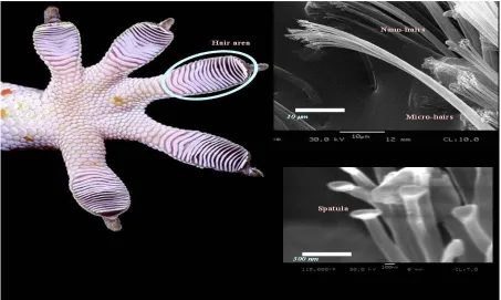
Gecko has always generated keen attention as it has the ability to climb surfaces, whether smooth or rough. To adhere to almost any surface with a controlled area, geckos use their micro/nano-scale high aspect ratio beta-keratin structures under their feet. The large surface area is due to the large hair like structure which give adhesion force also mainly due to the van der Waals forces [9]. A smaller scale hair seta of approximately of 5 microns is in every fibre and on each of these smaller scale strands sit several spatula which are of 200 nanometre in distance across. On every end of seta there are somewhere around 100 and 1000 spatula. As we know the surface region of each of the hair tips are little, the mix of the of billions of these hair makes the compelling surface territory substantial and van der Waals
strength gets to be critical. The produced grip power could be as high as 10N for every single 1cm2 [10]. Dry adhesion is more effective than the suction adhesion mechanism; there will still be adhesion on the parts of the
pad that have made contact if the dry adhesion pad encounters a crack or gap. This ability permits the robot to use dry adhesion method to climb up to the different varieties of surface Fig 2.4. shows the detailed image of lizards feet.
Fig 2.4
IMAGEPROCESSING
detection operators (canny edge detection). The different types of filters for filtering images are ex Gaussian filter, wiener filters etc. By visual inspection, contented detection results are obtained through this method.
Another method that has been developed for crack detection is image processing using neural network [17]. Using the filtering, the subtraction method, along with morphological operations cracks were distinguished from background image. To classify images back propagation neural network was used. The algorithm was tested making use of real surface images associated with the concrete bridge. Back-propagation neural network was trained using 105 images of concrete structure and the trained network was tested for new 120 new images with up to 90% accuracy.
III.DESIGN
Design is very important part of any project. It brings the imagined project into the view of the world and the rest of the world can relate to the work through the design. A design should be self-explanatory and at the same time it should be effective enough to caught the interest of the world. The design is kept simple in this project. The model that is selected is quadruped. As we trying to replicate the gait of a lizard, we chose to use a single module and three joints for the limbs.
We used SOILDWORKS to design the parts.
PROPERTIES BASE PLATE HINGES LEG PLATE
MASS (grams) 68.27 9.68 11
VOLUME (mm3) 24380.69 3455.61 11722.47
SURFACE AREA (mm2)
26870.74 5291.16 10841.07
MATERIAL Brushed 2014 T4 Aluminum
Brushed 2014 T4 Aluminum
Brushed 2014 T4 Aluminum
Table 3.1 Properties of Parts
BASEPLATE
The role play of a backbone of the robot is the base plate. It keeps them together and support parts so it should be strong, lighter and flexible. For the above stated purpose the shape of the base plate is designed as shown in figure 3.1.The base plate is also housing for servos. The slots made in the base plate will be attached to servo motors. The microcontroller and other electronic circuitry will be housed in the Plate.
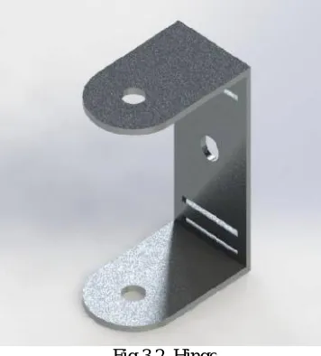
HINGE
To connect the servo motors together hinges are required. The will lead to the movement of servos relative to each other and will be instrumental in imparting motion similar to that of a gecko. Hinge was precisely designed as shown in fig 3.2. Brushed 2014 T$ Aluminium is the material chosen for the base plate.
SERVO
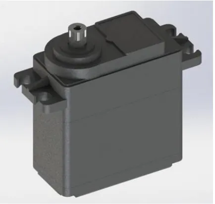
Selection of the servo motors has to be based on the total weight and dimension of the robot. Selection of the right servo motor is very essential because servo has to carry the load carrying work and if the lower capacity of the servo is used it would not able to move the robot forward. After the calculation we found out the weight of the robot to be 2.5-3 kg. To satisfy our requirement FEETECH FS5103B servo was chosen.
Fig 3.1. Base Plate
Modulation Analog
Torque 4.8v: 3kg-cm 6.0v: 3.2kg-cm
Speed 4.8v: 0.18sec/60o 6.0v: 0.16sec/60o
Weight 36.00 grams
Dimension 40.8mm X 20.1mm X 38.0mm
Motor Type Brushed
Gear Type Plastic
Rotation Dual bearing
Rotation Range 120o
Pulse width 900-2100µs
Table 3.2 Specification of Servo Motor
Fig 3.4. FEETECHFS5103B
LEGPLATE
Fig 3.3 LEGPLATE
FINALASSEMBLEDDESIGN
In figure 3.6 final assembled designs is shown. The base plate holds four servos, one at each corner. Through hinges those servos are connected to another set of servo. One more series of servo link uses that which finishes the motion mechanism of the robot. The last servos are linked to the leg pieces. For better distribution of pressure and to decrease load from the feet the vacuum pump are connected underneath the body. This arrangement also decreases the complexity arising due to connection of pipes in between the pump and the suction cup. The electronics are fitted over the base plate and have not been demonstrated in the figure in order to avoid complexity.
Fig 3.6 Assembled view of the wall climbing robot
.
IV.IMAGEPROCESSING
The primary objective of this project was to detect cracks on the surface of wall by means of image processing. In the literature survey part various algorithms and image processing methods were studied and analysed.
Image processing basically involves a number of processes, after which data is extracted from the image. The processes are
Obtaining the image
Applying filters to smoothen the image
Application of algorithm for required data extraction
Right after studying the various image processing methods we determined to go for edge detection in image using Canary Edge Detection method. Every crack in the surface will have edge separating out edges through the images will provide us specific section in image where we can look for cracks. Through visual inspection the final confirmation of cracks detection was done.
CANNYEDGEDETECTIONMETHOD
Canny edge detector or CED is an edge detection operator which uses a multi – stage algorithm to detect edges in images, John Canny developed it in 1986.
The process of canny edge algorithm can be broken down to 5 different steps: 1. Using Gaussian filter for image smoothening to remove the noise. 2. Determining the intensity gradient from the image [23]
3. Using non-maximum suppression to remove of spurious response in to edge detection.
Fig. 4.2 Non-Maximum Suppression [23]
A complete scan of the images is completed in the magnitude and direction in step 2. This task removes unwanted pixels. Every single pixel is checked as if it is the local maximum in its neighbourhood in the direction of the gradient. The process is shown in Fig 4.2. As shown in the fig. A in on the edge. Gradient direction is normal to the edge. The gradient directions are point B and C. Now Point A is compared to point B and c to see if the local maximum with respect to other. If you do it is considered for next stage otherwise, it is suppressed and eliminated and this step is usually continued till all images are covered.
The last result in this is a binary image with slim edges
4. Using double threshold to figure out potential edges. We need two threshold value, min Value and max Value in this stage. Any edge with intensity gradient more than max value, min value is a sure edge while the gradient with value less than min value are sure not part of any edge and should be discarded.
5. Monitoring edges by hysteresis: finalizing the detection of edges by suppressing all the other edges that are weak and not linked to strong edges.
Fig. 4.3 Tracking by Hysteresis [23]
It is crucial to select proper threshold values to get the desired result.
This stage removes small noise on assumption that edges are long continuous lines.
CANNYEDGEDETECTIONINOPENCV
In OpenCV all the above features are put within a single function, cv2.Canny(). The first argument is the input image while the second and third arguments are minValue and maxValue. Soble kernel is used to find the image gradient which by default is 3.
IMAGEPROCESSINGUSINGCANNYEDGEDETECTION
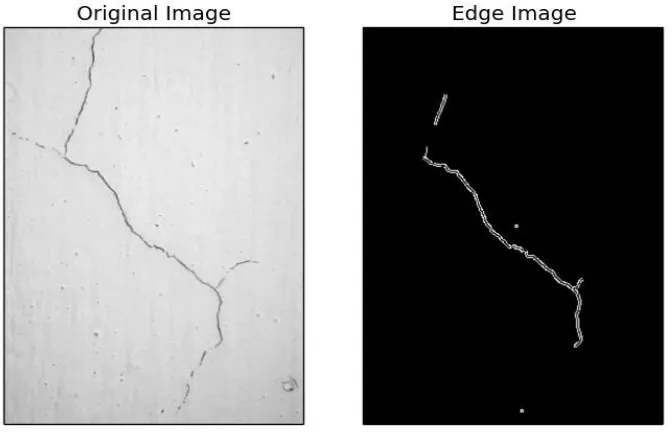
After that we changed the threshold value to get a more refined output by increasing the max Value to 400. The results are as shown in Fig. 4.5.
Fig. 4.5 Example of CED on a cracked surface, minValue = 100 maxValue = 400
Provides a more refined image and removes all the unwanted noises. This result was similar to the result we were expecting from our project.
After getting satisfactory results from sample images [24] we proceeded with the process and applied it to the images collected through our robot.
IMAGEPROCESSINGUSINGCANNYEDGEDETECTION
We applied the process described above to a few samples before implementing it into our project. First we applied it to a sample wall image with cracks on it. The cracks were visible and distinguishable through visual inspection.
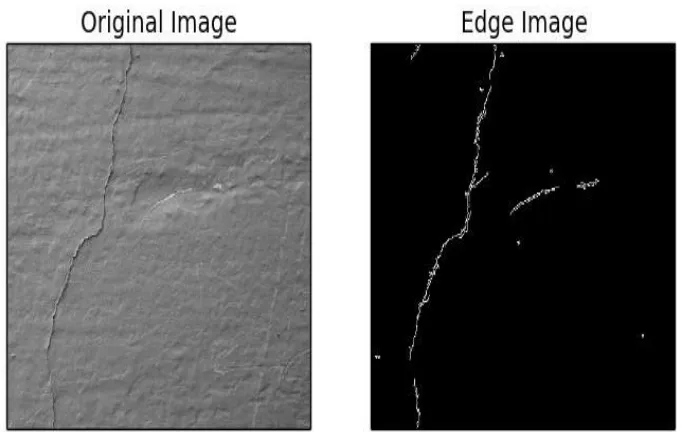
Fig. 4.7 Example of CED on a cracked surface, minValue = 100 maxValue = 600
The result is shown in Fig 4.6 as we applied the threshold values minValue = 100, maxValue = 400.
To get more refined output we changed the threshold value by increasing the max Value to 600. The results are as shown in Fig 4.7.
Fig. 4.8 Example of CED on a surface, minValue = 100 maxValue = 400
.
Fig. 4.9 Example of CED on a surface, minValue = 100 maxValue = 600
As shown in Fig 4.9, the results clearly ruled out the existence of crack at the maximum threshold value of 600 which was the desired result.
Fig. 4.11 Example of CED on a cracked painted surface, minValue = 100 maxValue = 600
We all then tested the procedure on the red coloured painted wall as displayed In Fig 4.10 and Fog 4.11. The original image has a white scratch mark in the centre. The procedure continues to show that mark as an edge even at higher threshold values and needs to be ignored during visual inspection.
V. RESULTSANDDISCUSSIONS
This project involved designing, manufacturing of the wall climbing robot and implementation of image processing techniques. Different designs and gait of geckos were studied and analysed before selecting the design and conceptualizing the movement pattern of the robot.
SOILDWORKS is used for designing.
Aluminium sheet was chosen for fabrication of parts. All parts were indigenously cut using CNC machine. CNC machine was carefully designed for accurate cutting of the parts.
Throughout the assembly the difficulty was faced over the selection of power supply unit. Several power sources were tired and tested. A 12V battery was used as a power source, however it failed to provide constant power as the heavy duty servos exhausted more current.
After several attempts and trails, SMPS unit was found to be the most reliable power source. Therefore the battery was replaced with a SMPS unit.
Various algorithm and processes K-Mean algorithm, template Matching, percolation, algorithm including Canny edge detection algorithm was selected for image processing.
As the algorithm identified the crack in a lighter background, it showed fluctuating outcomes when assessments were carried under lower illumination conditions.
Final crack identification was carried out using visual inspection.
VI.CONCLUSIONANDFUTURESCOPE
Image processing using canny edge detection provided reliable solutions. But it still requires human to observe and make the final decision about the presence of crack.
The future scope involves creating a fully automated robot which will have an internal energy supply and decision making program.
The robot will have the ability to detect cracks and will have the ability to decide the level of danger it possess. This will make the robot completely autonomous and will not require a human observer.
REFERENCES
1. T. Yano, T. Suwa, M. Murakami and T. Yamamoto, "Development of a semi self-contained wall climbing robot with scanning type suction cups," Intelligent Robots and Systems, 1997. IROS '97, Proceedings of the 1997 IEEE/RSJ International Conference on, Grenoble, 1997, pp. 900-905 vol.2., 1997.
2. A. Nagakubo and S. Hirose, "Walking and running of the quadruped wall-climbing robot," Proceedings of the 1994 IEEE International Conference on Robotics and Automation, San Diego, CA, pp. 1005-1012 vol.2., 1994.
3. Nishi, Akira & Miyagi, Hiromori. (1992). “A Wall-Climbing Robot Using Propulsive Force of Propeller: Mechanism and Control System in a Strong Wind”. Transactions of the Japan Society of Mechanical Engineers Series C. 58. 837-843. 10.1299/kikaic.58.837, 1992.
4. Guangzhao Cui, Keke Liang, JinchaoGuo, Huiping Li and DongdongGu“Design of a Climbing Robot Based on Electrically Controllable Adhesion Technology”,InternationalConference on Solid State and Materials Lecture Notes in Information Technology,, Vol.22, 2012.
5. HarshaPrahlad, Ron Pelrine, ScottStanford, John Marlow, and Roy Kornbluh,“Electro adhesive Robots—Wall Climbing Robots Enabled by a Novel, Robust, and Electrically Controllable Adhesion Technology” IEEE International Conference on Roboticsand Automation Pasadena, CA, USA, May 19-23, 2008
6. Rong Liu, Rui Chen, HuaShen and Rong Zhang.“Wall Climbing Robot Using Electrostatic Adhesion Force Generated by Flexible Inter digital Electrodes” InternationalJournal of Advanced Robotic Systems, DOI: 10.5772/54634, 2013.
7.,J. U. Jeon and T. Higuchi,“Electrostatic Suspension of Dielectrics”IEEE Transactionson Industrial Electronics, Vol. 45, No. 6, pp. 938 946,1998 8.Gregory Wile and Dean M. Aslam“Design, Fabrication and Testing of a Miniature Wall Climbing Robot Using Smart RoboticFeet”Micro And Nano TechnologyLaboratory, Department of Electrical and Computer Engineering, Michigan StateUniversity, E. Lansing, MI 48824, USA
9. K. Autumn, M. Sitti, Y.A. Liang,A.M. Peattie, W.R. Hansen, S. Sponberg, T. Kenny, R. Fearing, J.N. Israelachvili, and R.J.Full, “Evidence for van der Waals adhesion in gecko state”Proceedings of the National Academy of Sciences, vol. 99, pp. 12252-6, 2002.26
10., K. Autumn, Y. Liang, T. Hsieh, W, Zesch,W.P. Chan, T. Kenny, R. Fearing, and R.J. Full, “Adhesive force of a single gecko foot hair”Nature, 405, pp. 681-5, 08 June 2000
11., A.Nishi, Y. Wakasugi and K. Watanabe,“Design of a robot capable of moving on a vertical wall, Advanced Robotics” Vol.1, No.1, pp.33 – 45, 1986
12. A. NishiProc.“Bipedal walking robot capable of moving on a vertical wall for inspection use” 5th Int. Symp. On Robotics in Construction, Vol.2, pp.581 – 588,1988.
13. A. Nishi, M. Ohkuraand H. Miyagi, “A robot capable of moving on a vertical wall using thrust force”Proc. IEEE Int. Workshop on Intelligent robot and systems, IROS'90, pp.455 – 463,1990.
14.B.Santhi, G.Krishnamurthy, S.Siddharth, P.K.Ramakrishnan,“Automatic detection of cracks in pavements using edge detection operator“Journal of Theoretical andApplied Information Technology,.Vol. 36 No.2, 29th February 2012.
15.Moustafa, M.A.A; Suez Canal University,“Crack Detection Using Image Processing”Mathematics Department (EGYPT).
16.H. Elbehiery, A. Hefnawy, M. Elewa;“Surface Defects Detection for Ceramic Tiles Using Image Processing and Morphological Techniques (2005)” Proceedingof world Academy of Science, Engineering and Technology, 2005.
17.HyeongGyeong Moon and Jung-Hoon Kim;“Intelligent Crack Detecting Algorithm On The Concrete Crack Image Using Neural Network”
Department of Civil andEnvironmental Engineering, Yonsei University, Seoul, Korea
18. KengHuatKoh 1, M. Sreekumar 2 and S. G.Ponnambalam 1,*“Experimental Investigation of the Effect of the Driving Voltage of an Electroadhesion Actuator”.
19. Tellez, J.P.D.;Krahn, J.; Menon, C. “Characterization of Electro-Adhesives for Robotic Applications”, In Proceedings of the 2011 IEEE International Conference onRobotics and Biomimetic, Phuket, Thailand; pp. 1867–1872.7–11 December 2011
20.Wang, H.; Yamamoto, A.;Higuchi, T.“Electrostatic-Motor-Driven Electro adhesive Robot” In Proceedings of the 2012 IEEE/RSJ International Conference onIntelligent Robots and Systems, Vilamoura, Portugal; pp. 914–919.27, 7–12 October 2012.
21.Liu, R.; Chen, R.; Shen, H.; Zhang, “Wall climbing robot using electrostatic adhesion force generated by flexible interdigital electrodes”R. Int. J. Adv. Rob.Syst. 2013, 10, 1–9.
![Fig. 2.3.Schematic of the electro adhesion actuator. [18]](https://thumb-us.123doks.com/thumbv2/123dok_us/1579492.1194422/5.595.70.529.515.705/fig-schematic-electro-adhesion-actuator.webp)


![Fig. 4.2 Non-Maximum Suppression [23]](https://thumb-us.123doks.com/thumbv2/123dok_us/1579492.1194422/12.595.124.461.428.560/fig-non-maximum-suppression.webp)