Performance of Rectangular Skirted Footing
Resting on Sand Bed Subjected to Lateral load
Prof. S. W. Thakare 1, A.N.Shukla 2
Associate Professor, Department of Civil Engineering, Government College of Engineering, Amravati, Maharashtra,
India1
P.G. Student, Department of Civil Engineering, Government College of Engineering, Amravati, Maharashtra, India2
ABSTRACT: Skirted foundations are considered a viable foundation type for a variety of offshore applications, facilities for the oil gas industry and structures where scour is major concern. These foundations are gradually replacing piled foundations which leads to cost savings through reduction in materials and in time required for installation. In offshore structures, power transmitting cables and earth retaining structures, the lateral forces acting on the footings may be dominant. Thus there is need to study performance of skirted footings subjected to lateral loads. In the present study, lateral loading tests were performed to shed some lights on the performance of rectangular skirted footings. Different parameters studied were effect of embedment depth of skirt to footing width (D/B) ratio, number of skirts provided to footing and different load inclinations and their effects on the ultimate horizontal loads attained by footing was investigated. From the results of laboratory tests, it was found that increase in the number of skirts and D/B ratio increased the ultimate lateral load carrying capacity of footings significantly. Locations of skirts with respect to loading direction also have significant effect on the ultimate lateral load carrying capacity of shallow footings. Load carrying capacity of footing increases with increase in inclination of load in plan.
KEYWORDS: Rectangular skirted footing, embedment depth, ultimate horizontal capacity.
I. INTRODUCTION
Skirted foundations are an alternative to pile foundations in offshore structures and oil and gas facility. The term skirted foundations is used to identify shallow foundations with vertical/ inclined thin structural elements fixed along its periphery, “called skirt”. The skirts form an enclosure in which soil is confined and works as a unit with the overlain foundation to transfer superstructure load to soil essentially at the level of skirt tip. Peripheral skirts can be used with new and existing shallow foundations of square, rectangular, and circular shape. Shallow footings are subjected to lateral forces induced by earthquake movements, wind loads, water wave pressure, lateral earth pressure and transmitting power cables. In offshore structures, power transmitting cables and earth retaining structures the lateral forces acting on the footings may be dominant. The present study aims at exploring performance of rectangular skirted footing subjected to lateral load under different parameters.
II. LITERATURE REVIEW
A review of previous studies on skirted foundations in terms of behavior, performance, analysis approaches by numerical and analytical study is carried out. The objective of this review is to identify the contributions established by researchers on skirted foundations and identify the gap in research for the present study.
1. Saleh1 et al. (2010) studied “Performance of Skirted Strip Footing Subjected to Eccentric Inclined Load” using PLAXIS version 7.1. Parameters selected for study were various load inclination angles, load eccentricities and skirt length. Study concluded that inserting a skirt under the footing edge reduces the lateral movement of soil.
.3. Joshi and Mahiyar 5(2000) conducted an experimental study to find the effectiveness of angle shaped footing under eccentric loading. They concluded that the footing projection along the longer side having a minimum vertical settlement than the footing along the shorter side.
4. Amr Z El Wakil7 carried experimental investigation to determine horizontal capacity of skirted shallow footings on sand. It was concluded that as the length of skirt to footing diameter ratio increased up to 1.5, the ability of skirted footings of resisting lateral load increased.
5. Joshi and Mahiyar8 (2009) conducted series of loading tests on a square angle shaped footing on sand. They concluded that failure load for an angle shaped footing depends on angle and depth of footing projection. 6. Ashraf Kamal Nazir, Wasim R. Azzam9 (2010) conducted experimental analysis to improve B.C on soft clay
with and without skirts. There was an improvement in the load bearing capacity using both partially replaced sand piles with and without confinement.
III. METHODOLOGY
The main objective of experimental investigation in the present study was to study the response of rectangular skirted footing resting on sand bed subjected to lateral load.
1. Test material and their properties • Test sand
For the model tests, cohesion-less, dry, clean and washed Kanhan sand was used as the foundation material. This sand is available in Nagpur region of Vidharabha, Maharashtra. The geotechnical and engineering properties of the sand were determined as per relevant I.S codes and are shown in Table 1.
Table 1: Properties of sand
Sr. No. Properties Values
1 Specific gravity 2.60
2
γmax
(kN/m3) 16.993
γ
min (kN/m3) 15.594 Angle of internal friction (φ0) 27o
5 Cohesion (kN/m2) 2
6 D10 1.0
7 Coefficient of uniformity (Cu) 1.033
8 Coefficient of curvature (Cc) 1.15
9 IS classification SP (Medium Sand)
• Model footing
The model footings of rectangular shapes were fabricated by using mild steel plates having dimensions 120 mm x 100 mm and 10 mm thickness. The skirts were made of M.S plates of thickness 5 mm welded to the sides of the footing. The depth of the skirts was corresponding to different depth/width (D/B) ratio of footing as detailed in the program. The skirted rectangular footings are shown in Fig 1.
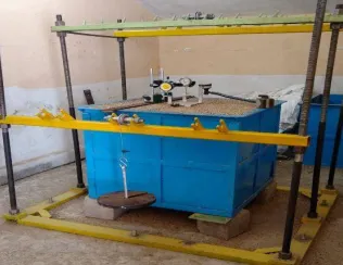
2. Test setup
The test setup consisted of steel tank of size 0.65 m x0.65 m x0.65 m and a loading frame to apply lateral loads to the footing as shown in the Fig 2. Lateral loads were applied to the footing by means of dead weights placed on a loading hanger connected to a flexible steel rope, strung over a pulley supported by the loading frame. The loading frame had provision to place the pulleys at different locations so as to change the inclination of loading in the plan.
Figure 2: Test setup for experimental investigation
3. Test procedure
The tank was filled with sand by rainfall technique up to its top. The height of fall to achieve the desired relative density was determined by performing a series of trials with different height of fall. In the present investigation, the height of fall was selected as 35 cm in rainfall technique and the corresponding relative density was maintained at 47.5 %. The top surface of sand bed was levelled and checked by spirit level. The skirted footing was then placed on the top of sand bed and pushed into the sand by displacement method till the skirts were inserted in the sand bed for its full height. Care was taken to drive footing vertically downwards by checking with level tube. After skirts were pushed in the sand bed, surface was levelled using sharpened straight steel plate. After driving the footing, it was left undisturbed for 12 hours. Fig 2 shows experimental setup. One dial gauge was placed against the braces welded to the footing to measure the horizontal displacement, and two dial gauges supported on the top surface to measure average vertical settlement of footing as shown in Fig 3. The static lateral loads were applied in increments by adding dead weights through the loading arrangement. Each increment was kept constant for ½ hour. The load was applied horizontally at 10 mm above the formed sand surface. The horizontal and vertical displacements of the skirted footing was measured within an accuracy of 0.01 mm using three dial gauges.
Figure 3: Schematic diagram of test set-up for horizontal loading
Table 2: Details of test program
Sr.No Parameters Details of parameter
1 No. of Skirts 1, 2 and 4
2 D/B ratio (Depth of skirt/width
of footing) 0.5B, 1B, 1.5B, 2B
3
Direction of load
(i) Horizontal
(ii) applied at an angle of 150 with the axis of skirted footing
(iii) Applied at an angle of 300 with the axis of skirted footing.
IV. EXPERIMENTAL RESULTS AND DISCUSSIONS
The lateral load displacement and vertical displacement behavior of skirted footings were determined by conducting model tests. The vertical displacement of the footing was considered as the average vertical displacement of the two edges of the footing. Rotation of footing edge was also calculated as the difference between vertical displacement at load edge and rear edge divided by distance between two edges of footing. The maximum horizontal load was determined from the load displacement curve. The failure load taken by footing is taken as the load at which footing takes maximum load prior to failure.
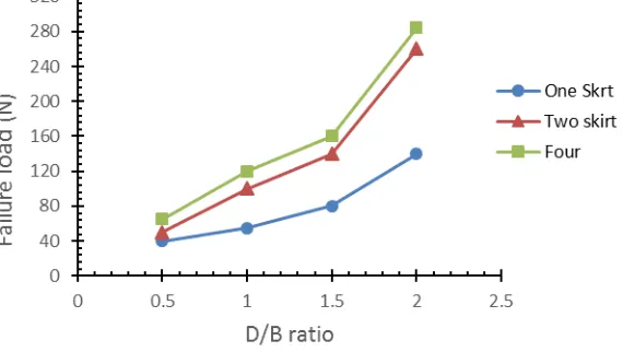
4. Effect of Skirt Depth to footing width (D/B) Ratio
Effect of different Skirt depth to footing width (D/B) ratio was explored by changing D/B ratio as 0.5, 1, 1.5, and 2. Fig. 4 shows variation of failure load with respect to D/B ratio. From the Fig 4, it was observed that the lateral load carrying capacity of skirted footing improved rapidly with increase of skirt depth to footing width ratio. Table 3 shows % increase in horizontal failure load for different D/B ratio of skirt as compared to D/B ratio 0.5.
Table 3: Increase in failure load for different D/B ratio
D/B ratio
% increase in horizontal failure load for different number of skirts
One Two Four
0.5 - - -
1 37.5 100 84.5
1.5 100 180 146.2
2 250 420 370.5
5. Effect of Number of Skirts
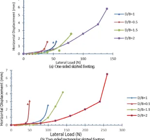
Effect of different number of skirts was explored by changing number of skirts attached to footing. Fig 5 (a), (b), (c) shows Lateral load vs horizontal displacement curves for one sided, two sided and four sided rectangular skirted footing respectively.
(a) One sided skirted footing.
Lateral Load (N)
Lateral Load (N)
(c) Four sided skirted footing.
Figure 5: Lateral Load vs Displacement curves for different number of skirted footings.
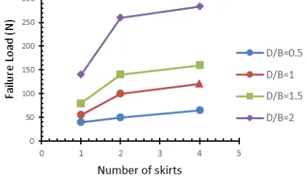
Fig 6 shows horizontal failure load of footing corresponding to different number of skirts for different D/B ratio of skirts.
Figure 6: Failure load vs number of skirts attached to footing for different D/B ratios .
From the graph it is observed that the horizontal load carrying capacity of the footing increases as the number of skirts increases. The increase of horizontal load carrying capacity may be attributed to the increase in confinement which is provided by the surrounding soil with increase in number of skirts. However, increase is marginal when skirt attached to footing increases from two to four. The increase in failure load for different D/B ratios in terms of percentage as compared with that D/B ratio 0.5 is shown in Table 4.
Table 4: Increase in failure load for different D/B ratios
D/B ratio
% increase in horizontal failure load for different number of skirts
One Two Four
0.5 - - -
1 37.5 100 84.5
1.5 100 180 146.2
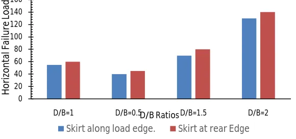
6. Effect of Location of Skirt
Effect of location of skirt was studied by providing skirts at different locations w.r.t. load applied to the footing. For one sided skirted footing and two sided skirted footing, skirts were provided at different locations w.r.t load direction as shown in Fig 7.
(a) Single sided skirt provided along load edge b) Single sided skirt provided along rear edge
(c) (d)
c) Two sided skirted footing, skirt provided normal to load d) Two sided skirted footing, skirt provided parallel to load Figure 7: Different arrangements of skirt with respect to applied load
From Fig 8 (a) and (b), it was seen that failure load is higher for one sided skirted footing when skirt was provided at rear load edge. For two sided skirted footing, lateral load taken by footing was more, when skirts were provided normal to load direction.
(a) One sided skirted footing
0 20 40 60 80 100 120 140 160
D/B=1 D/B=0.5 D/B=1.5 D/B=2
H
o
ri
zo
n
ta
l F
ai
lu
re
L
o
ad
D/B Ratios
Figure 8: Horizontal failure load for different D/B ratios
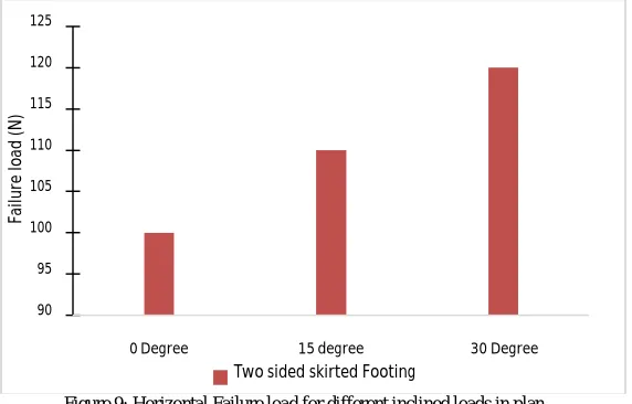
7. Effect of load inclination in plan
Effect of different load inclination in plan was explored by changing the inclination of load in plan as 150 and 300. Fig 9 shows lateral load at failure for different load inclinations in plan for optimum case i.e. two sided skirted footing with D/B ratio 2.
Figure 9: Horizontal Failure load for different inclined loads in plan
From values, it is evident that load carrying capacity of footing increases with increase in inclination of load in plan.
V. CONCLUSIONS
Based on experimental investigations the following conclusions are drawn-
i) The horizontal load carrying capacity of the skirted footing increases as the number of skirts increases. The increase in horizontal load carrying is substantial when number of skirts is increased from one to two and marginal when increased from two to four. Two sided skirted footing may be considered optimum.
ii) As the depth of skirt to footing width increases from 0.5 to 2, the ability of skirted footings of resisting lateral load increases up to 300%.
0 50 100 150 200 250 300
D/B=0.5 D/B=1 D/B=1.5 D/B=2
H o ri zo n ta l F ai lu re L o ad D/B Ratios
Two Sided Skirt provided parallel to Load
Two sided Skirt provided normal to Load Direction
90 95 100 105 110 115 120 125
0 Degree 15 degree 30 Degree
Fa ilu re lo ad (N )
two sided skirted footing, load carrying capacity is more when skirts are provided normal to load direction. Load carrying capacity of footing increases with increase in inclination of load in plan.
iv)The average lateral as well as vertical deformation of footing at failure increases with increase in number of skirts attached to footing, as well as with increase in D/B ratio of footing.
REFERENCES
1. Saleh M. N, Alsaied E. Ahmed and Azza M. Elleboud, “Performance of Skirted Strip Footing subjected to eccentric Inclined Load” EJGE. Vol. 13, 2010.
2. Hisham T.E. et.al “Bearing Capacity and Settlement of Skirted Shallow Foundations on Sand,” International Journal of Geomechanics ASCE., Vol. 13, pp 645-652, 2013.
3. Pusadkar S. S. and Bhatkar T., “Behavior of raft foundation with inclined skirt using PLAXIS 2D” Indian Geotechnical Conference., Vol-3, No 6, 2013.
4. Britta Bienen et.al, “Numerical modelling of a hybrid skirted foundation under combined loading” Computers and Geotechnics Elsevier.,Vol.45, pp 127-139, 2012.
5. Joshi D. and Mahiyar H., “Angle Shaped Rectangular Footing with Variable Angle of Footing Projection under Eccentric Vertical Load” EJGE. Vol.14, 2009.
6. Joshi D. and Mahiyar H., “Behavior of an angle shaped footing under eccentric and inclined loading”. Indian Geotechnical Conference., Vol 3, pp 609-613, 2009.
7. W.R Azzam and Farouk A,“Performance of Skirted Strip footing on sand slopes Loaded with Skirted strip footing”. EJGE. Vol.15, pp 795-811, 2010.
8. Amr Z El Wakil, “Horizontal capacity of skirted shallow footings on sand”. Alexandria Engineering Journal. Vol.49, pp. 379–385, 2010. 9. Nazir A. K., Wasim R. A, “Improving the B.C of Footing on soft clay with sand pile with and without Skirts”. Alexandria Engineering Journal
Elsevier. Vol.49, pp 371-377, 2010.
10. Ajitha P.S. et.al, “Performance of square footing with a structurally skirt resting on sand” Indian Geotechnical Conference., Vol.15, pp 12531365, 2014.
11. Indian Standards- IS: 2720 (Part 3)-1980 “Methods of test of soils, determination of specific gravity, fine, medium and coarse grained soils”, New Delhi.
12. Indian Standards- IS: 2720 (Part 4) -1985 “Methods of test of soils, grain size analysis- mechanical method”, New Delhi.
13. Indian Standards- IS: 2911 (Part 4) -1985 “Part for lateral load test on piles” Indian Standard Code of Practice for Design and Construction of Pile Foundations, New Delhi.