Design of Neural Network Based Sensorless
Induction
Motor
Speed
Control
Drive
Alka Nimbhorkar 1, Dr Manisha Dubey 2
PhD Scholar, Department of Electrical Engineering, Maulana Azad National Institute of Technology, Bhopal,
Madhya Pradesh, India1
Professor, Department of Electrical Engineering, Maulana Azad National Institute of Technology, Bhopal,
Madhya Pradesh, India2
ABSTRACT: Design an Artificial neural network controlled Speed control drive for an 3-phase Squirrel Cage Induction Motor (SCIM) for various application. To Development an artificially intelligent speed controller drive using Neural Network (back propagation type) based speed feedback approach to avoid speed sensor in feedback loop of Induction motor . Target for a cheap design using sensorless speed control approach.
In the designing of a speed feedback controller, the main criterion is the controllability of speed of an induction motor without using any speed sensor, these characteristics which can be achieved by speed sensor controller.
KEYWORDS:Artificial intelligence techniques, ANN, Induction motor drive, Electrical, Power Electronics.
I.INTRODUCTION
II. RELATEDWORK
Recently in Indian railways DC Motor is replaced by Induction Motor, for that it is necessary to apply it with a three phase variable voltage variable frequency (VVVF) inverter and four quadrant converter, whose controls are quite complicated, which is possible only by use of GTOs and microprocessor based control system.
1. IM has no brushes in armature as its squirrel cage type, less wear and tear as no brushes needed 2. Robust, cheaper to build and Technically feasible
3. Power to weight ratio of induction motor is much higher than the DC motor 4. Its 80186/16-bit MICAS S2 Microprocessor based control which is costlier. 5. Here required hall effect type speed sensor for speed feedback.
So, sensorless economical and effective approach is to reduce sensor cost and disadvantageous caused by it [1].
III. SPEEDESTIMATORIMPLEMENTATION
Neural Network based Speed Estimation is employed for the purpose of indirect measurement. The Inputs used by the Speed Estimator are three phase voltages and two phase currents The output delivered is an estimate of the current speed. The Motor is subjected to a speed profile based run and the Three phase voltages and current along with the frequency and speed are logged This forms the Training and Test Data for the Speed Estimator . The Neural Network based Speed Estimation in three phases:
1. Uses the Phase Voltages Vr, Vy, Vb and Phase currents Ir & Iy as Inputs
2. NN generates a speed estimate as output which is fed to IM by closed loop control PI/Fuzzy logic controller. 3. Training using Back-Propagation Algorithm
First Phase – Data Generation Phase Second Phase – Training Phase Third Phase –Test/ Application Phase
The Motor is subjected to a speed profile based run and the Three phase voltages and current along with the frequency and speed are logged. This forms the Training and Test Data for the Speed Estimator
IV. PROCEDURE FOLLOWED:DATA GENERATION,TRAINING &TESTING FOR NNSE
The Data generator is run to simulate the drive system and generates the three phase voltages and three phase currents along with the operating frequency and speed. System Operation parameters : Ramp up time, Highest set Speed, initial set speed, Motor HP. Simulink GUI – allows for user to start the data generation and Stop it after full simulation is over, as shown in (a) Pre-training steps and and (b) shows steps to followed after run simulation.
(a) (b)
(c) (d)
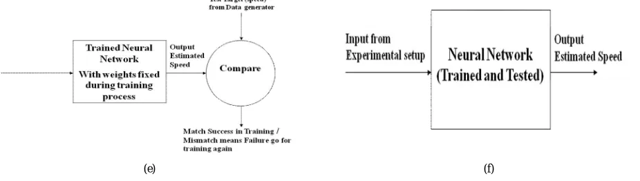
In the fig (e) shows the Testing phase, which is used to verify that the training is indeed successful or not. If not than trained again with more data.
(e) (f)
Fig. 2. Procedure followed for Data Generation, Training and Testing (a) Overview of Speed Estimator- Data Generation – Pre-training (b) Speed Estimator- Data Generator (c) Overview of Speed Estimator- Neural Network Training and Testing (d) Speed Estimator- Neural Network Training
(e) Speed Estimator- Neural Network Testing (f) Speed Estimator- Neural Network Application
Once proper training is done the network is able to give proper data for the test results also. Generally the test data is separate from the training data and hence unknown to the network before testing. Once training and testing is done the network is considered to be ready for application purpose. The fixed weights of trained steps and tested neural network are programmed in the microcontroller for calculating estimate of the speed which is shown in Fig (f) Application phase which followed after successful testing.
In application mode we provide the current inputs to the neural network and it estimates the speed. This Estimated speed and its derivative (difference from previous value) fed to the FLC for computation of the control input for changing the frequency of the drive.
V. STANDARDMODELUSEFORDATAGENERATIONTOTRAINNEURALNETWORK(NN)
First Phase – Data Generation Phase: Drive system is setup for Data generation phase using Matlab Simulink. Drive uses Vector control for the purpose of PWM generation. The IM model as Fig 3 given below, provides Speed feedback for data generation.
An input profile is provided to the model for running the motor
(
Power Supply= 3-phase AC, 415 Volts, 50 Hz. Motor Specification= 3-phase, 2 HP, 450 Volt, DC bus voltage = 630 volts, Chopper output/ inverter input= 630 Volts, IGBT O/P = 400 Volts, let Load Torque of SCIM =10 NM) and
Microcontroller I/P= 5 Volts.The Phase Voltages Vr, Vy, Vb and Phase currents Ir & Iy along with the current speed and frequency are recorded in a file.
Fig. 3 Major parts of the drive system
VI. DATAGENERATION-OPERATION
Speed Profile Generation : Speed Profile is generated using Matlab timer object. Consists of Speed Ramp Up and final constant speed for some time followed by the ramp down to achieve motor stop. Ramp up is achieved by increasing the frequency, up to the point where speed reaches to maximum limited by slip of the motor. Ramp down is by means of decreasing the Frequency up to the point the motor stops.
Motor Drive Operation: Speed Profile is generated using Matlab script is fed to the SVPWM Vector control module.
It further generates the PWM trigger pulses for the inverter module. This causes the inverter to give AC waveform as input to the three phase Induction motor. The motor is loaded by a constant torque which user can set.Scope is used to record the Voltages and currents along with the frequency and speed for Data generation.
VII.TRANINGPHASESPEEDPROFILEANDITSRESULTS
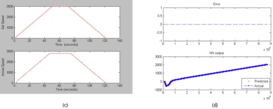
Training Speed Profile: apply this profile for data generation in model setup as given in (a). The motor is provided non zero Set speed at time = 0 seconds, then at t= 50 seconds it reaches the max speed possible, 3000rpm and retains it. After that at t= 72 the ramp down start s and continues till the motor does not stop (t=122).
(a) (b)
The Set speed and Actual speed mentioned in (c), first plot shows the reference or set speed and second plot shows actual or rotor speed, so both can compare easily. Similarly (d) is Estimated Error & Actual Speed, in first plot shows the error i.e. the difference between these and second plot shows the predicted and actual speed given below.
(c) (d)
Fig. 4.Training Phase Speed Profile and its Results (a) Training phase Speed Profile (b) Scope/ Recorded wave forms (c) Training phase Set speed and Actual speed (d) Training phase Estimated Error & Actual Speed.
VIII. TESTINGPHASESPEEDPROFILEANDITSRESULTS
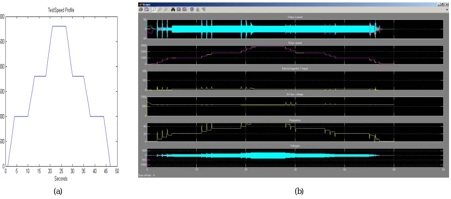
Testing by changing reference speed profile as per (a) of the drive system and observing error as difference in set & actual speed:
1. The motor starts at t=0 sec, then at t= 20 seconds it reaches the max speed possible, 2800rpm and retains it. After that at t= 30 the ramp down starts and continues till the motor does not stop (t=47).
There are six signals plotted by the Scope/ Recorded wave forms after simulation, as shown in (b), and saved in MotorScopeData at end of simulation. The variables are of Fig (b) first plot shows stator voltages (Vr, Vy, Vb), second plot shows Rotor speed (Set and actual), third plot shows Electromagnetic torque, fourth plot DC voltage, fifth plot Frequency and sixth plot Currents (Ir, Iy,Ib).
(a) (b)
(c) shows Testing input Output plots, first plot shows the three phase voltages and three phase currents and in second plot shows current rotor speed, similarly in (d) shows Estimated Error & Actual Speed, in first plot given estimated error between reference and rotor speed and second plot shows waveform of estimated and actual speed .
(c) (d)
IX. APPLICATIONPHASE
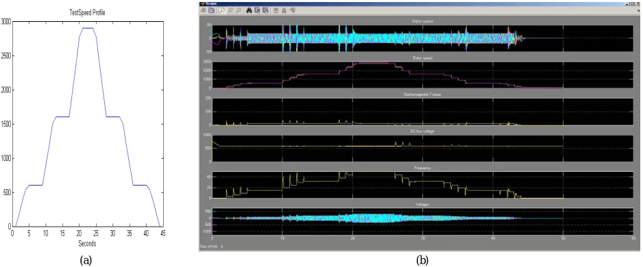
Apply speed profile as shown in (a) upon the trained and tested neural network for data generation in model setup. Speed Ramps up with two stops. Starts from 0 Ramps up to 600 stabilise for short time. Again ramps up to 1600 stabilise for short time. Further Ramps up to 2900. A total of about 44 sec simulation time.
There are six signals plotted by the Scope/ Recorded wave forms after simulation, as shown in (b), and saved in MotorScopeData at end of simulation. The variables are of Fig (b) first plot shows stator voltages (Vr, Vy, Vb), second plot shows Rotor speed (Set and actual), third plot shows Electromagnetic torque, fourth plot DC voltage, fifth plot Frequency and sixth plot Currents (Ir, Iy,Ib).
(a) (b)
(c) shows Testing input Output plots, first plot shows the three phase voltages and three phase currents and in second plot shows current rotor speed, similarly in (d) shows Estimated Error & Actual Speed, in first plot given estimated error between reference and rotor speed and second plot shows waveform of estimated and actual speed .
(c) (d)
X. EXPERIMENTALRESULTS
Simulation provides useful insight into operations. Matlab and Simulink can be considered as essential tool for simulation. Neural Network based speed Estimation is practically possible using simulation. In this paper proposed an neural network based speed observer and PI/ fuzzy logic speed controller algorithms using PIC 18F4431 microcontroller to increase the speed-sensorless drive. By using MATLAB simulation from the experimental setup, the results carried on a 2HP Induction motor with PIC18F44431 micro-controller. This has robust speed observation and tracking performances even at load variation or variable-speed operation, shows that the proposed algorithms observe and correct respectively the speed over the entire speed range.
The conclusion of all the tests carried out is that the estimated motor response and the reference or actual speed are quite similar, and there is nearly no error in the steady state.
XI. CONCLUSION
In this paper, we are limited to the neural network based speed observer and further planning is to speed control using fuzzy logic approach on place of PI controller. PIC18F4431 Microcontroller based control, development and Simulation of complete drive circuit including FLC Simulation, PWM Simulation and NN Simulation on MATLAB. Software Development is at two levels On Microcontroller using Embedded C language Firmware, FLC, NNSE. On PC/ Desktop GUI programming using Visual Basic 6 and Communicating with the Drive unit using Serial Port.
XII. ACKNOWLEDGEMENT
The author wishes to thanks Dr Manisha Dubey, Professor whom under guidance and encouragement, able to write the paper. She also like to acknowledge the MANIT Bhopal, MP for providing a chance as research student to enhance knowledge in engineering field.
REFERENCES
[1] A.K Rawal, Director “Traction rolling stock, three phase technology” published by Indian Railways institute of electrical engg (IRIEEN), in 18 Aug 2010.
[2] Faizal Arya Samman, Tajuddin Waris ,Tiara Dwi Anugerah, Muhammad Nuralim Zain Mide, “Three-phase Inverter Using Microcontroller for Speed control Application on Induction motor”, Makassar International Conference on Electrical Engineering and Infonnatics (MICEEI), Indonesia, ISBN: 978-1-4799-6726-1, (c) 2014 IEEE, 26-30 November 2014.
[3] C. H. Salerno, Dr A. T. LeFio, MSc R. A. Araujo, MSc, “A Fuzzy Speed Control for a Three-phase Induction Motor”, Paper accepted for presentation at PPT 2001, IEEE Porto Power Tech Conference, Porto, Portugal, (c) 2001 IEEE, 10th -13th September.
[4] Mouna Ben Hamed & sabita lassaad, “ANN speed sensorless Fuzzy control of DRFOC induction motor drives”, Journal of practises & technology, ISSN 1583-1078, Issue 16, Jan-jun 2010, p. 129=150.
[5] Bimal K Bose, life fellow IEEE “Modern power electronics and AC drives” published by Pearson education copyright in 2002.
[6] Zonal electric traction training centre avadi, Chennai, ISO 9001: 2000 certified “Study Material for 3 Phase Locos Course (WAP5/WAP7/WAG9)”
[7] J Karvinen, “Three phase AC traction drives: Design and service experience” IEE E proceeding, Vol 134, Pt B No.3, May 1987. [8] WS Chan, B Mellitt, NB Rambukwella, “Whole system simulator for AC railways”, UK, pp 368-372.
[9] V Varus,S nayak,“Speed Control of Induction Motor using Fuzzy Logic Approach” Dept. of ele. Engg. NIT Raurkela.
[10] Meenu Gupta, Reena Kamboj& Rinku Dhiman, “Performance & Analysis of Fuzzy Logic Controller Based Induction Motor Drive System Using Simulink”, Special Issue of IJCCT, ISSN (ONLINE) : 2231–0371, ISSN (PRINT) : 0975–7449, Volume- 3, Issue-1.
[11] V.N. Ghate, S.V. Dudul, “Artificial Neural Network Based Fault Classifier For Three Phase Induction Motor” , International Journal of Computational Intelligence Research ISSN 0973-1873 Volume 5, Number 1 (2009), pp. 25–36.
[12] Chin-Teng Lin and C. S. George Lee, “Neural-network-based fuzzy logic control and decision system,” IEEE Transactions on Computers, Volume: 40 , Issue: 12 , Dec. 1991, Pages:1320 – 1336.
[13] Thomas M Jahns, V Blasko “ Recent advances in power electronics technology for industrial and traction machine drives” IEEE fellows, SR member, Vol 89, No.6, June 2001.
[14] A Mishra, P Choudhary, “Speed control of an induction motor by using indirect vector control” Internation journal of emerging tech & advance engg, vol 2, issue 12, Dec 12.