Speed Control Drive for Induction Motor to
Control the Flow of Dye in Paper Mill
Bhuvanesh.M 1, Venkatesan.S 2, Jayaprakash.E 3, B.Gopalakrishnan 4
U.G. Student, Department of EEE, Angel College of Engineering and Technology, Tirupur, Tamilnadu, India 1,2,3
Assistant Professor, Department of EEE, Angel College of Engineering and Technology, Tirupur, Tamilnadu, India 4
ABSTRACT: This paper describes a Quasi-Z-Source Indirect Matrix Converter (QZSIMC) fed induction motor drive
to control the flow of dye in paper mill. Voltage Source Inverter (VSI) and Current Source Inverter (CSI) have been used to control the speed of the induction motor which in turns controls the flow of dye. Recently Matrix Converter (MC) has been an excellent competitor for the VSI or CSI for its compactness. The voltage transfer ratio of the VSI, CSI and MC has been limited to 0.866. Thus the efficiency of these converters is less. To improve the voltage transfer ratio the Quasi-Z- Source Network (QZSN) is to be used between voltage source and Indirect Matrix Converter (IMC). Modification in the shoot through duty ratio of the QZSN varies the voltage transfer ratio greater than 0.866. The different voltage transfer ratio is needed for different voltage sag condition. For a variation of the duty ratio of the QZSN, the fuzzy logic controller and ANFIS has been presented. The proposed ANFIS-based PWM is stable and faster than the traditional based PWM method.
KEYWORDS: fuzzy logic controller, voltage transfer ratio, ANFIS, voltage sag, QZSIMC, PWM, voltage sag.
I. INTRODUCTION
1.12. The ZSN has an additional advantage that allows short circuit of the source as a consequence commutation becomes straightforward and effortless.
II. LITREATURE SURVEY
Research has been carried out in two ways one is on the track of an QZSIM converter and other is on track of an FUZZY with ANFIS Controllers. Researchers have worked in QZSIM conversion and have tried to remove drawbacks in conversion system. They have also worked in AC-AC conversion area and have used different topologies and have overcome many drawbacks in existing converters.
D.Sri Vidhya and Dr.T.Venkatesan proposed the “Quasi-Z-Source Indirect Matrix Converter Fed Induction Motor Drive for Flow Control of Dye in Paper Mill” with the fuzzy controller. Here we use this concept and proposed the system with ANFIS and FUZZY logic controller.
In this paper , we proposed an indirect matrix converter fed induction motor drive with ANFIS and fuzzy logic controllers. By using fuzzy logic and ANFIS controllers the voltage transfer ratio is maintained and the speed of an induction motor is controlled.
III.EXISTING SYSTEM
Flow of dye depends on the speed of induction motor. When voltage sag occurs in the supply voltage it affects the speed of induction motor. To control the flow of dye even under voltage sag conditions, the variable boost QZSIMC with fuzzy controller has been proposed. In this paper a variable boost capability of the QZSIMC has been tested and analyzed for different voltage sag conditions.
Fig. 1. Block Diagram of Existing Fuzzy Controller for Quasi-Z-Source Indirect Matrix converter fed Induction motor drive controlling the Dye Pump.
IV.PROPOSED QZSIMC TO DYE PUMP
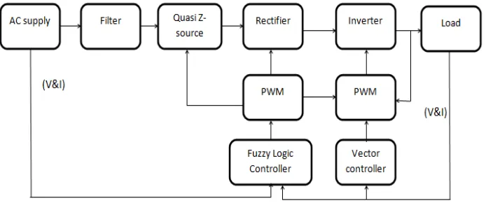
Flow of dye depends on the speed of induction motor. When voltage sag occurs in the supply voltage it affects the speed of induction motor. To control the flow of dye even under voltage sag conditions, the variable boost QZSIMC with ANFIS and fuzzy controller has been proposed. In this paper a variable boost capability of the QZSIMC has been tested and analysed for different voltage sag conditions.
Fig. 2. Block diagram of proposed system
The topology of QZSIMC has six parts. It has filter, QZSN, rectifier, inverter, induction motor and dye pump. The PI controller or Fuzzy logic controller determines the shoot through duty ratio D of QZSN and rectifier side modulation index mr. Inverter side modulation index mi of the SVM is controlled with the vector controller. To obtain a controllable input power factor, Space Vector Modulation (SVM) technique is required which modulates the rectifier. At the same time, the output voltage fed SVM is applied to the inverter to modulate three-phase output voltage.
Table. 1.
V. QUASI-Z-SOURCE INDIRECT MATRIX CONVERTER FED INDUCTION MOTOR DRIVE
Two capacitors (Cx1, Cx2), two inductors (Lx1, Lx2) and one of bidirectional switches (Sx) has been connected to form QZSN for any one of phase x; x = a, b, c. Similarly, three QZSN has been connected to the three phase supply.
Fig. 3. The topology of the discontinuous QZSIMC fed induction motor.
Operating Principle of the QZSIMC
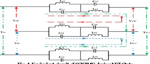
QZSIMC operates in two states namely Non-Shoot- Through (NST) and Shoot-Through (ST) state. One switching period Ts has NST and ST state. Tnst and Tstare the time period of NST and ST state. Shoot through duty ratio is well-defined as D=Tst/Ts. In NST state the switches (Sx) is closed. Fig. 4 represents the equivalent circuit of QZSIMC in NST state. During this state, the inductor is parallel to the capacitor.
Fig. 4. Equivalent circuit of QZSIMC during NST State.
VI. ADAPTIVE NEURO-FUZZY INFERENCE SYSTEMS (ANFIS):
The controls signal will then increase or decrease the conduction period of bi-directional switches that will either achieve the desired power factor at the input stage. The scheme utilizes Sugeno-type Fuzzy Inference System (FIS) controller, with the parameters inside the FIS decided by the neural-network back propagation method. The ANFIS is designed by taking current (I) and error in current (e) as the inputs. The output stabilizing signals is computed using the Fuzzy membership functions depending on these variables. ANFIS Editor is used for realizing the system and implementation. In a conventional fuzzy approach the membership functions and the consequent models are fixed by the model designer according to a prior knowledge. If this set is not available but a set of input output data is observed from the process, the components of a fuzzy system (membership and consequent models) can be represented in a parametric form and the parameters are tuned by neural networks. In that case the fuzzy systems turn into neuro-fuzzy system. A fuzzy system can explain the knowledge it encodes but can’t learn or adapt its knowledge from training examples, while a neural network can learn from training examples but can not explain what it has learned.
Adaptive neuro fuzzy inference system (ANFIS) incorporates the best elements of fluffy frameworks and neural systems, and it can possibly catch the advantages of both in a solitary edge work. ANFIS is a sort of simulated neural system that is predicated on Takagi-sugeno fluffy deduction framework, which is having one info a done yield. Using a given information set, the tool compartment capacity of ANFIS develops a fluffy deduction framework (FIS) where as the participation work parameters are tuned (balanced) using a back engendering calculation.
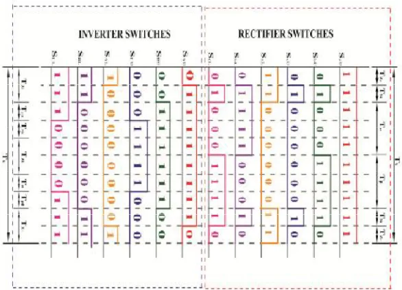
Fig. 5. SVM Switching Sequence with insertion of ST.
Layer 1: This layer is also kenned as fuzzification layer where every hub is spoken to by square. Here, three enrolment capacities are doled out to every information.
The trapezoidal and triangular enrolment capacities are utilized to reduce the computation burden as shown in Fig.5.
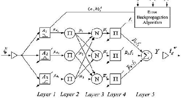
Fig .6. Schematic of the proposed ANFIS-based control architecture.
where the value of parameters (ai, bi) changes with the change in error and accordingly generates the linguistic value of each membership function. Parameters in this layer are referred as premise parameters or precondition parameters.
Layer 2: Every node in this layer is a circle labelled as Π. which multiplies the incoming signals and forwards it to next layer.
But in our case there is only one input, so this layer can be ignored and the output of first layer will directly pass to the third layer. Here, the output of each node represents the firing strength of a rule.
Layer 4: Every node in this layer is a node function
where the parameters ( )are tuned as the function of input (ξ). The parameters inthis layer are also referred as consequent parameters.
Layer 5: This layer is also called output layer which computes the output as given below:
The output from this layer is multiplied with the normalizing factor to obtain the active power current component (id*’).
Fig. 7. Fuzy membership functions
Fuzzy Variables: Output Current, error (e) in current and Output Control Signal (CS) are detection as Negative Large (NL), Negative Medium (NM), Negative Small (NS), Zero (Z), Positive Large (PL), Positive Medium (PM) and Positive Small (PS).
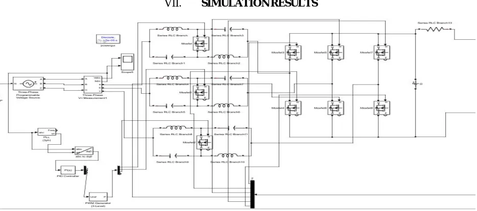
VII. SIMULATION RESULTS
The above figure shows the simulink model (back end) of the PROPOSED system.
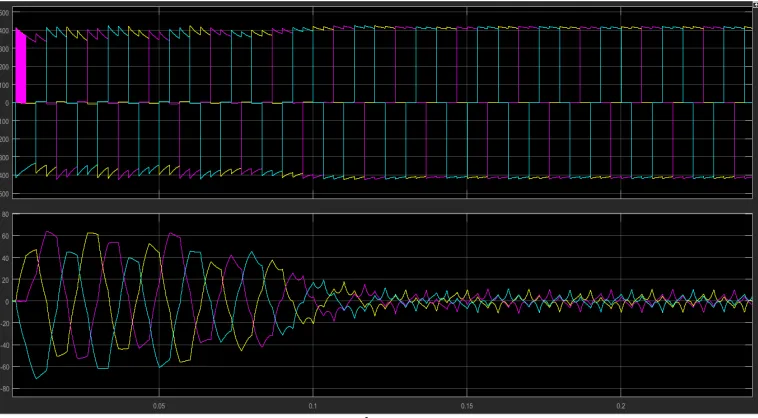
Fig . 8. shows the simulation result of Three phase voltage (Va,b,c) & current (Ia,b,c) of the existing system.
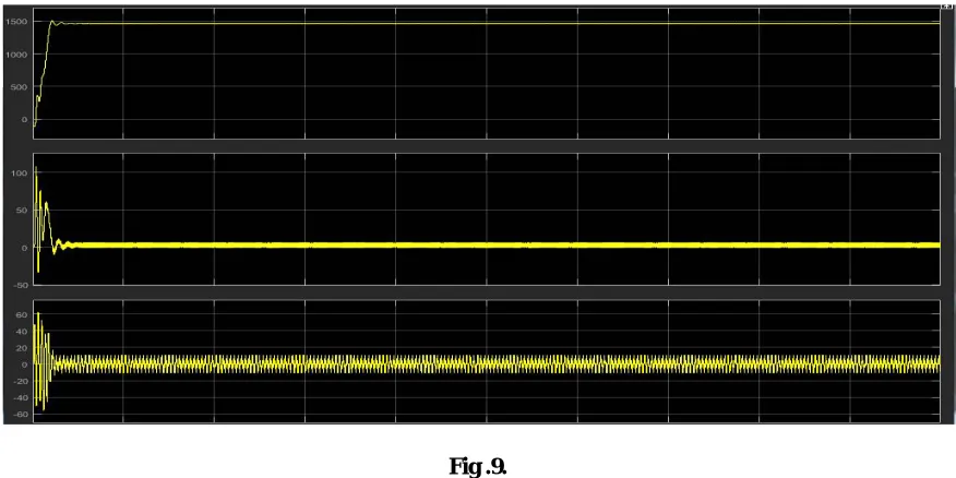
Fig .9.
Fig. 9. shows the simulation result of Motor speed(rpm),Motor torque(Nm),Stator current(is) of the existing system.
VIII. CONCLUSION
In this paper, based on the ANFIS controller, a variable shoot through duty ratio has been proposed for Quasi-Z-Source Indirect Matrix Converter fed induction controlling the Dye pump and it has been compared with PI controller. Analysis for RMSE,ITSE and ITAE were made for speed response of PI controller and ANFIS controller for different voltage sag condition. Simulation results indicate the proposed ANFIS controller has better speed response than PI controller.
REFRENCES
[1] D.Sri Vidhya, Dr.T.Venkatesan “Quasi-Z-Source Indirect Matrix Converter Fed Induction Motor Drive for Flow Control of Dye in Paper Mill” IEEE Transactions on Power Electronics , DOI 10.1109/TPEL.2017.2675903, IEEE
[2] B. K. Bose, “Global Energy Scenario and Impact of Power Electronics in 21st Century,” IEEE Transactions on Industrial Electronics, vol. 60, no. 7, pp. 2638-2651, July2013.doi: 10.1109/TIE.2012.2203771.
[3] J.W. Kolar, T. Friedli, J. Rodriguez and P. W. Wheeler, “Review of Three-Phase PWM AC–AC Converter Topologies,” IEEE Transactions on Industrial Electronics, vol. 58, no. 11, pp. 4988-5006, Nov. 2011.
[4] L. Gyugi, and B. Pelly, “Static Power Frequency Changers, Theory, Performance and Application,”John Wiley & Sons, New York, USA, 1970.
[5] A. Alesina and M. G. B. Venturini, “Analysis and Design of Optimum-Amplitude Nine-Switch Direct AC-AC Converters,” IEEE Transactions on Power Electronics, vol. 4, no. 1, pp. 101-112, Jan. 1989.
[6] T. Friedli, J. W. Kolar, J. Rodriguez, P. W. Wheeler, “Comparative Evaluation of Three-Phase AC–AC Matrix Converter and Voltage DC-Link Back-to-Back Converter Systems,” IEEE Transactions on Industrial Electronics, vol. 59, no. 12, pp. 4487-4510, Dec. 2012.
[7] P. W. Wheeler, J. Rodriguez, J. C. Clare, L. Empringham and A. Weinstein, “Matrix Converters: A Technology Review,” IEEE Transactions on Industrial Electronics, vol. 49, no. 2, pp. 276-288, Apr. 2002.
[8] J. Rodriguez, M. Rivera, J. W Kolar and P. W. Wheeler, "A Review of Control and Modulation Methods for Matrix Converters,” IEEE Transactions on Industrial Electronics, vol. 59, no. 1, pp. 58-70, Jan. 2012.
[9] Y. Tamai, H. Ohguchi, I. Sato,A. Odaka,H. Mine and J. I. Itoh, “A Novel Control Strategy for Matrix Converters in Over-modulation Range,” Power Conversion Conference, Nagoya, pp. 1049-1055, Apr. 2007.
[10] PawełSzcześniak, "Three-phase AC-AC Power Converters Based on Matrix Converter Topology, Matrix-reactance frequency converters concept", Springer-Verlag London 2013.
[11] F. Z. Peng “Z-source inverter,” IEEE Transactions on Industry Applications, vol. 39,no. 2,pp. 504-510,Apr. 2003.