ABSTRACT
SHRIVASTAV, NITIN. A Network Simulator model of the DOCSIS protocol and a solution to the bandwidth-hog problem in Cable Networks. (Under the direction of Dr. Arne Nilsson and Dr. David Thuente.)
A number of broadband access solutions have been developed in the recent years to provide high speed Internet access to the residential users or the ‘last-mile’. Some of the prominent technologies include Cable access, Digital Subscriber Loop, Integrated Services Digital Network, Satellite and Wireless. The cable broadband access is gaining widespread popularity.While several approaches to broadband access over cable have been proposed (e.g., DVB/DAVIC and IEEE 802.14), the industry is converging on the architecture
developed by the Multimedia Cable Network System (MCNS) group (referred to as the Data-Over-Cable Service Interface Specification or DOCSIS standard). The DOCSIS Radio Frequency Interface specification defines the Media Access Control (MAC) layer as well as the physical communications layer.
support for DOCSIS. The Network Simulator implementation is conformant to the DOCSIS RF-interface specifications with support for Quality of Service features.
The second part of this thesis presents a solution for congestion control in cable networks. It has been observed in cable networks that few heavy bandwidth users can cause severe congestion affecting the performance of the other users. Typically, the end user applications incorporate end-to-end congestion control for best-effort traffic (e.g. TCP congestion control). However, with the growth of the Internet, it might no longer be practical to rely on all end-nodes to use end-to-end congestion control. There is a need for the
participation of the network itself in controlling the resource utilization. A solution is
proposed where the central entity (known as Cable Modem Termination System) in the cable network identifies and restricts the bandwidth of selected best-effort flows in times of
A NETWORK SIMULATOR MODEL OF THE
DOCSIS PROTOCOL AND A
SOLUTION TO THE BANDWIDTH-HOG PROBLEM IN THE
CABLE NETWORKS
by
NITIN SHRIVASTAV
A thesis submitted to the Graduate Faculty of North Carolina State University
in partial fulfillment of the requirements for the Degree of
Master of Science
COMPUTER NETWORKING
Raleigh 2003
APPROVED BY:
Dr. Jim Martin Dr. Andy Rindos
BIOGRAPHY
Acknowledgements
I would like to thank Dr. Jim Martin for his invaluable guidance, motivation, and
encouragement and for providing a great opportunity to work with him. I would like to thank Dr. Arne Nilsson, Dr. David Thuente and Dr. Andy Rindos for accepting to be on my
committee and reviewing my thesis. I would like to thank Dr. M. Vouk for allowing me to use the EGRC office space and machines.
I would like to thank my parents and my sister for their incredible support and encouragement.
TABLE OF CONTENTS
LIST OF TABLES………viii
LIST OF FIGURES………ix
1 INTRODUCTION………1
1.1 Last mile delivery………..1
1.2 Community Antenna TeleVision Networks………..1
1.2.1 Network Topology………..2
1.2.2 Cable Data Network Operation………..4
1.3 Standards for CATV Networks……….7
1.3.1 Data over Cable Interface Specification……….7
1.3.2 IEEE 802.14 Working Group……….8
1.3.3 Digital Audio Visual Council……….9
1.3.4 IETF IP over Cable Data Network (IPCDN) Working Group…….10
1.4 Contributions……….………..11
1.5 Thesis Layout………..11
2 DOCSIS OVERVIEW………...……….13
2.1 DOCSIS Evolution………..13
2.2 Protocol Features……….14
2.2.1 Interfaces………..14
2.2.2 Communication Protocols………16
2.2.4 Media Access Control Specifications………..20
2.2.5 Media Access Control Protocol Operation………..23
2.2.5.1 Upstream Bandwidth Allocation………..23
2.2.5.2 Sending Requests………..25
2.2.5.3 MAP Transmission and Timing………26
2.2.5.4 Protocol Example………..26
2.2.5.5 Upstream Contention resolution………...28
2.2.6 Quality of Service………29
2.2.6.1 Upstream Service Flow Scheduling Services………31
2.2.6.2 Fragmentation………32
2.2.6.3 Concatenation………33
3 ARCHITECTURE……….34
3.1 Network Simulator Overview……….34
3.2 Network Simulator –2 Model……….38
3.2.1 Introduction………..38
3.2.2 Overview of the Model………39
3.2.3 User-configurable parameters………..41
3.2.4 Simulation Statistics……….47
3.2.5 CM Node Design………..49
3.2.5.1 Introduction………49
3.2.5.2 Service flow implementation……….…50
3.2.5.3 Unsolicited Grant Service……….….51
3.2.5.5 Best-effort Service ………60
3.2.5.6 Receiving frames on the RF interface………67
3.2.5.7 Concatenation and Fragmentation………..67
3.2.6 CMTS Node Design………..67
3.2.6.1 Receiving/Sending frames on the RF interface………….68
3.2.6.2 Upstream channel bandwidth management………70
3.2.7 NS – 2 Implementation Details……….73
3.2.7.1 Concatenation implementation………..74
3.2.7.2 Fragmentation implementation………..75
3.2.7.3 Physical Layer Framing……….75
4 STUDY OF THE MODEL……….76
4.1 Verifying Scheduler Functionality………..76
4.1.1 UGS………..78
4.1.2 rtPS………...81
4.2 Scheduling delay Analysis………..84
4.3 Use of Fragmentation………..91
4.4 Performance Study………..93
4.4.1 Upstream FTP traffic………96
4.4.2 Downstream FTP traffic………...98
4.4.3 Web traffic………..101
4.4.4 Summary of results……….104
5 SOLUTION TO THE BANDWIDTH-HOG PROBLEM………107
5.2 Related work………..107
5.3 Our Approach………109
5.4 Algorithm………..111
5.4.1 Detecting impact of heavy flows problem………111
5.4.2 Identification of heavy flows……….113
5.4.3 Type and duration of the Punishment………114
5.4.4 Pseudocode………115
5.5 Simulation Results………116
5.6 Discussion……….125
6 CONCLUSIONS AND FUTURE WORK………..129
6.1 Conclusions………...129
6.2 Future work………...129
7 LIST OF REFERENCES……….131
LIST OF TABLES
Table 2.1 Upstream channel rates for DOCSIS 1.0, 1.1 and 2.0………...14
Table 4.1 UGS flow parameters……….79
Table 4.2 Observed Jitter………...79
Table 4.3 rtPS flow parameters………..82
LIST OF FIGURES
Figure 1.1 Tree and Branch Architecture……….2
Figure 1.2 HFC Architecture………4
Figure 1.3 Data over Cable System………..5
Figure 1.4 DVB/DAVIC Reference Model……….9
Figure 2.1 Data-Over-Cable Reference Architecture……….15
Figure 2.2 Data forwarding through the CM and the CMTS……….17
Figure 2.3 Protocol stack on the RF Interface………18
Figure 2.4 Generic Frame Format………..22
Figure 2.5 MAC Header Format……….22
Figure 2.6 Data PDU Format……….23
Figure 2.7 Allocation MAP………24
Figure 2.8 Protocol Example………..26
Figure 2.9 Classification within the MAC layer………30
Figure 3.1 User’s view of Network Simulator………...34
Figure 3.2 Network Simulator Class Hierarchy……….36
Figure 3.3 Network Simulator Node Structure………..37
Figure 3.4 Network Simulator Link Structure………...37
Figure 3.5 Network Simulator Packet Structure………38
Figure 3.6 DOCIS Network Topology………..39
Figure 3.7 FSM for UGS………..53
Figure 3.9 FSM for Best-effort service……….63
Figure 3.10 DOCSIS Class Hierarchy………..74
Figure 4.1 Relationship between grant interval and tolerated grant jitter……….76
Figure 4.2 Simple Cable Topology………...78
Figure 4.3 Model Parameters………78
Figure 4.4 Observed Jitter vs. Number of CMs………81
Figure 4.5 Observed Jitter vs. Number of CMs………84
Figure 4.6 Model Parameters………85
Figure 4.7 Scheduling delay vs. Number of CMs………86
Figure 4.8 Scheduling delay vs. Number of CMs………87
Figure 4.9 Scheduling delay vs. Number of CMs………88
Figure 4.10 Scheduling delay vs. Number of CMs………..89
Figure 4.11 Scheduling delay vs. Number of CMs………..91
Figure 4.12 Model Parameters……….92
Figure 4.13 Upstream Utilization vs. Number of CMs………93
Figure 4.14 Upstream Transmission……….94
Figure 4.15 Simple Cable Scenario………..96
Figure 4.16 Model Parameters and Experiment Descriptions………..96
Figure 4.17 Upstream throughputs………...97
Figure 4.18 Upstream utilization………..97
Figure 4.19 Upstream collision rates………...98
Figure 4.20 Downstream Scenario………..99
Figure 4.22 Downstream utilization……….100
Figure 4.23 Upstream collision rates………100
Figure 4.24 Web Traffic Topology………...102
Figure 4.25 Model Parameters………..102
Figure 4.26 Downstream web scenario – Downstream utilization………...103
Figure 4.27 Downstream web scenario – Upstream collisions……….103
Figure 5.1 Simulation Topology………115
Figure 5.2 Model Parameters………116
Figure 5.3 Avg. web response time………..117
Figure 5.4 Bandwidth of heavy flow vs. Time……….117
Figure 5.5 Avg. web response time……….119
Figure 5.6 Bandwidth of heavy flow vs. Time………120
Figure 5.7 Avg. web response time……….121
Figure 5.8 Bandwidth of heavy flow vs. Time………122
Figure 5.9 Avg. web response time……….123
Figure 5.10 Bandwidth of heavy flow vs. Time………..124
1. INTRODUCTION
This chapter presents the motivational background, contributions and the layout of this thesis.
1.1 Last mile delivery
Traditionally, delivery of Internet access to the residential area, or the “last mile” as it is more commonly referred to, has relied upon the Plain Old Telephony System (POTS) network. However, residential users and small businesses now demand fast connectivity technologies to access the advanced web services like rich multimedia content and video on demand. This has fueled the demand for broadband access. It is predicted that the number of broadband cable users in North America will rise from about 12 million (in 2002) to about 26 million by 2006 [3].
Consumers are moving away from dialing-up using their phone lines towards new faster and improved connectivity technologies. To meet this demand a number of rival technologies like DSL, cable, satellite, wireless, powerline, and ISDN technologies have been developed. These technologies provide speeds up to 50 times faster than the traditional dial-up access. These broadband connections are always on, making Internet an integral part of our lives.
1.2 Community Antenna TeleVision (CATV) Networks
The source or the “Headend” (HE) is located at the root and the subscriber at the “leaves”. Since CATV were initially designed for one-way broadcast, from HE to the subscriber, they required physical modifications such as bi-directional Radio Frequency (RF) amplifiers, as well as development of protocols to allow point-to-point communications over the shared link. A discussion of the physical characteristics and structure of modern CATV networks is provided in the next section. Then basic cable data network operation is discussed.
1.2.1 Network Topology
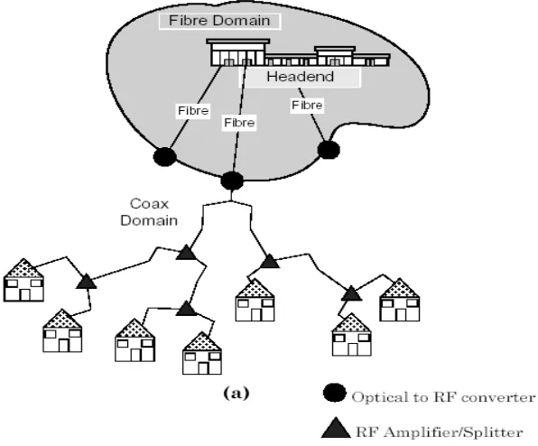
Majority of the CATV networks are based on the “tree and branch” architecture [4] as shown in Figure 1.1. There exist many other alternative cable topologies, like switched star, not very widely adopted [5]. There are three main tree and branch architectures: Hybrid Fiber Coaxial (HFC), Fiber To The Curb (FTTC) and Fiber To The Home (FTTH).
These three architectures differ in how close to the subscriber the fiber terminates. CATV networks transitioned from an all coaxial to Hybrid Fiber Coaxial (HFC) networks due to an increased requirements for more channels, lesser noise and reduced signal attenuation. Use of optical fiber gives the advantage of lower maintenance costs, higher bandwidth and no electromagnetic noise.
HFC
The HFC network architecture consists of fiber links connecting the HE with Service Access Points (SAP). A number of homes are then connected to a SAP using coaxial cable. In the downstream direction, HFC networks use 450 to 860 Mhz for digital services and 50 to 450 Mhz for analogue broadcast services. The Upstream spectrum is 5-42 Mhz. Quadrature Amplitude Modulation (QAM) and Quaternary Phase Shift keying (QPSK) modulation is used to support digital services. Over a 6Mhz channel, 64 QAM carries 27Mbps of user data taking forward error correction into account. Figure 1.2 represents a typical HFC architecture.
FTTC
FTTH
Fiber to the home architecture is solely based on fiber links. Fiber links run down to the last mile into each home. Implementation costs of FTTH networks are higher as compared to previously mentioned topologies. Bandwidths up to 155Mbps can be achieved due to all fiber architecture.
Figure 1.2: HFC Architecture
1.2.2 Cable Data Network Operation
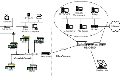
All the cable modems communicate with the Cable Modem Termination System (CMTS) located at the central office of a cable service provider as shown in Figure 1.3. Typically, a CMTS serves hundreds of cable modems over a network that can stretch to over 100 kms.
The CMTS connects to the Internet and other networks, sending and receiving user packets. When a packet arrives from the Internet at the CMTS, a processor module converts the IP packets into MPEG packets and performs error checks. Subsequently, the packet is modulated onto a carrier wave using QAM/FEC or QPSK modulation. The output is then forwarded to the subscriber. The cable modem at the subscriber’s location converts the radio frequency information back to IP packets and sends them to the end device.
Figure 1.3: Data Over Cable System
Users will observe significant variation in the downstream data rate as the downstream channel is shared by all active users. There may be brief periods where all the bandwidth is available to just a few users, which would allow huge download speeds. Cable operators can also increase the bandwidth allocation by making additional channels available for data. Since there is only one sender in the downstream direction (CMTS), so no channel access mechanism is needed.
The upstream channels typically occupy lower frequencies that are subject to noise. Since there can be multiple senders in the upstream direction, so a channel access control mechanism is needed to govern control of the common channel. As the number of users increase, there will be a performance drop.
Noise on the upstream connection is caused due to electrical interference from home appliances, old cable, improperly shielded cable etc. The noise problem puts a severe limit on the upstream bandwidth. Synchronous Code Division Multiplexing (S-CDMA) modulation technique is being promoted to increase the available bandwidth in the Upstream.
1.3 Standards For CATV Networks
Cable standards are being designed to provide interoperability between cable modems and the head-end gear. This will give flexibility to the subscriber to buy off-the-shelf cable modems conforming to the standards. Standards benefit both the subscribers and the operators by making connection easier and promoting new applications. The most important standards are outlined below.
1.3.1 Data over Cable Interface Specification (DOCSIS)
1.3.2 IEEE 802.14 Working Group
This working group was disbanded in March 2000. The standardization process was slow within IEEE, which failed to observe the time to market constraint and hence lost the industry support. A brief description of the proposed specification is given.
This group has defined the physical layer and a Medium Access Control (MAC) layer protocol for the HFC networks. The architecture specifies an HFC cable plant with a radius of 80 kilometers from the head end. The group's goal was to develop a specification for delivering Ethernet traffic over the network. Asynchronous Transfer Mode (ATM) networking was also considered for the delivery of multimedia traffic.
There are three physical layer specifications reflecting the European, the United States and Japanese requirements (types A, B and C). The upstream channel bandwidth is 8 Mhz for type A and 6 Mhz for types B and C. The Physical layer is composed of the Transmission Convergence (TC) and the Physical medium Dependent (PMD) sublayers. The MAC sublayer consists of the MAC Convergence Subprocess (MACCS), the ATM and the MAC Access Arbitration (MAA) sublayers. This sublayering helps in multiplexing the Logical Link Control (LLC) and the ATM traffic streams effectively.
The specification supports ATM services like Constant Bit Rate (CBR), Variable Bit Rate (VBR) and Available Bit Rate (ABR). The data transmission is based on a grant/request scheme. The CMTS controls access to the upstream channel by allocating transmission opportunities to the users for contention and reservation-based transfer [7].
1.3.3 Digital Audio Visual Council (DVB/DAVIC)
DAVIC was a non-profit group that promoted digital audio-visual applications and services based on the specifications that maximized interoperability across countries and applications/services [8]. DAVIC developed a digital video broadcast reference model that is popular in Europe and preferred by the European Cable Communications Association (ECCA), a European cable industry organization. DAVIC completed its work and closed in 2000. The DVB/DAVIC reference model is shown in Figure 1.4.
Figure 1.4: DVB/DAVIC Reference Model
Between the service provider and the user, two channels are established – Broadcast channel (BC) and the Interaction channel (IC). BC is unidirectional broadband channel to transmit audio, video and data. IC is a bi-directional channel and is composed of – Return Interaction
from the service provider to the user. The user terminal interfaces with the broadcast channel as well as interaction channel. The interface between the user terminal and the broadcast network is via the Broadcast Interface Module (BIM). Interactive Interface Module (IIM) provides interface between the user terminal and the interaction channels. A 64-octet slot format is used for transmission of data in the upstream. In the downstream direction, downstream In Band (IB) and downstream Out of Band (OOB) are used. For IB, MAC PDU frames are encapsulated into MPEG2 frames.
DVB/DAVIC supports Internet telephony, VoIP and videoconferencing. At the MAC layer, four access modes are supported. Contention Access mode allows users to send information any time with the risk to experience collisions. The Fixed-rate and Reservation access mode are contentionless. The Interactive Network Adapter (INA) provides a fixed amount of slots to a specific Network Interface Unit (NIU) or a requested bit-rate until NIU demands to stop the connection. In the Ranging Slot Access mode, slots are used for adjusting the time delay and power.
The modulation scheme is QPSK for upstream with data rates of 6176,3088,1544 or 256 kbps. QPSK is also used for downstream OOB and QAM is used for downstream IB [7].
1.3.4 IETF IP over Cable Data Network (IPCDN) Working Group
working on bandwidth management and guarantees using RSVP, security using IPSec, and management using SNMP [9].
1.4 Contributions
The contributions of this thesis are: Design, Implementation and Study of a NS-2 model of the DOCSIS 2.0 MAC protocol and Design and analysis of an algorithm to solve the bandwidth-hog problem in cable networks. The NS-2 model developed supports most of the important features of the protocol and can be extended easily to incorporate new features. The model will be submitted to ‘NS-2’ maintainers to make it available to the Internet research community. The model can then be used by the researchers to explore various research issues in Cable Networks.
Congestion caused by heavy bandwidth users pose a great concern to the cable service providers. These heavy bandwidth users can cause severe degraded performance for other users. The service providers are considering several options like Service-tiered approach or Bandwidth usage fees to solve this problem. The algorithm presented in this thesis provides an alternative to these pricing solutions and can be effectively used by the Cable Service Providers to do congestion control in the cable network.
1.5 Thesis Layout
problem. Chapter 6 concludes the thesis with a summary of achievements and suggestions on future work.
2. DOCSIS OVERVIEW
This chapter presents an overview of the DOCSIS features and operations [10].
2.1 DOCSIS Evolution
The MCNS group has produced a series of specifications for DOCSIS. The first specifications, known as DOCSIS 1.0 was mainly for high speed Internet access. The standard allowed multiple vendors to build interoperable products resulting in large number of deployment. 23 million DOCSIS 1.0 equipments had been shipped worldwide as of 2002. DOCSIS 1.0 was targeted primarily at the residential market. It lacked enhanced QoS and security features to support multi-media applications like videoconferencing in the Small office/Home office (SOHO) and the small business market.
Table 2.1: Upstream channel rates for DOCSIS 1.0, 1.1 and 2.0[11]
Modulation Bandwidth (Mhz) Raw data rate (kbps) Version
QPSK 1.6 2,560 DOCSIS 1.0/1.1
16QAM 1.6 5,120 DOCSIS 1.0/1.1
QPSK 3.2 5,120 DOCSIS 1.0/1.1
16QAM 3.2 10,240 DOCSIS 1.0/1.1
32QAM 3.2 12,800 DOCSIS 2.0
64QAM 3.2 15,360 DOCSIS 2.0
16QAM 6.4 20,480 DOCSIS 2.0
32QAM 6.4 25,600 DOCSIS 2.0
64QAM 6.4 30,720 DOCSIS 2.0
Cablelabs, a non-profit research and development consortium, has established a certification program for vendors to get official DOCSIS certification if there equipments pass a series of interoperability test. Till Jan 2003, 228 vendors have been certified for DOCSIS 1.0 CM and 29 for CMTS. 64 vendors have been certified for DOCSIS 1.1 CMs and 22 for CMTS. For DOCSIS 2.0, 5 CM vendors have been certified and 1 for CMTS [3].
In the rest of this chapter, we discuss DOCSIS 2.0 protocol features and operation.
2.2 Protocol Features
2.2.1 Interfaces
Figure 2.1: Data-Over-Cable Reference Architecture
The following interfaces are defined:
Data Interfaces: There are two data interfaces, namely CMCI [12] and CMTS-NSI [13].
CMCI corresponds to the interface between the CM and the customer premises equipment (CPE). CMTS-NSI is the interface between the CMTS and the data network.
Operations Support Systems Interfaces: This interface defines the service provisioning
model and the network management MIBS [14]. The interface is between the network elements and the Operation Support Systems (OSS).
RF Interfaces: RFI is the core interface that defines communication between the CMs and
the CMTS. Three RF interfaces are specified:
• Between the CM and the cable network
• Between the CMTS and the cable network, in the upstream direction
Security Interfaces (BPI): BPI specifies the mechanisms and algorithms used for secure
communication between the CMTS and the CMs.
CMTRI: DOCSIS protocol may be deployed over CATV networks that have not been
modified to support bi-directional communications. CMTRI defines the communication between the CM and the CMTS when the upstream path is provided by POTS line.
In the rest of this chapter, we focus on the RF interface specifications.
2.2.2 Communication Protocols
In this section an overview of the communication protocols used in data over cable systems is presented.
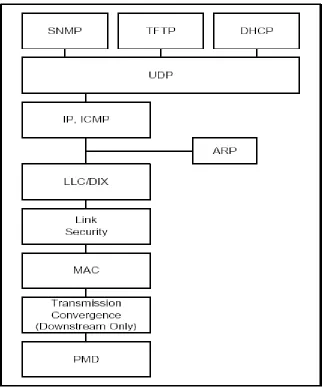
Data forwarding through CM is transparent bridging. ISO/IEC10038 forwarding rules are used with some modifications. The protocol stacks at the CMTS and the CM for data forwarding is shown in Figure 2.2.
Figure 2.3: Protocol Stack on the RF Interface
The CMTS must either forward ARP packets or provide proxy-ARP service to the CMs. The network layer protocol is IP version 4 and migrating to IP version 6. Higher layer services can be used transparently over IP.
and accept those that are destined for the CM or the CPE. CMs communicate with other CMs only through the CMTS. The upstream channel has many transmitters (CMs) and one receiver (CMTS). Time is slotted on the upstream channel and the CMTS provides the time reference as well as controls the usage of each slot.
The Physical layer is comprised of - Transmission convergence sublayer (In downstream direction only) and Physical media dependent sublayer.
In the next section we look at the Physical layer features of DOCSIS 2.0.
2.2.3 Physical Layer
Physical media dependent (PMD) sublayer: The upstream PMD sublayer uses a
FDMA/TDMA (TDMA mode) or FDMA/TDMA/S-CDMA (S-CDMA mode) burst type format. Using MAC messages, CMTS configures the mode to be used by all the CMs. FDMA indicates that multiple RF channels are used in the upstream band. A CM is configured to transmit over a single RF channel. This RF channel is shared by a number of CMs via dynamic assignment of time-slots (TDMA). If S-CDMA is used, then multiple CMs can transmit simultaneously on the same RF channel during the same TDMA time-slot. For upstream channels, following modulations are provided for TDMA and S-CDMA : QPSK, 8QAM, 16QAM, 32QAM, 64QAM.
The downstream PMD must conform to ITU-T Recommendations J-83. 64 QAM and 256 QAM modulation is supported on the downstream channel.
Downstream transmission convergence sublayer (DTCS): DTCS is interposed between
for future multiplexing of video and data over the PMD sublayer. The downstream is defined as a continuous series of 188-byte MPEG [10] packets. The packet consists of 4-byte header and 184 bytes payload. The header identifies the type of the payload (Data-over-cable MAC or video). MAC frames may span several MPEG packets and several MAC frames may exist within an MPEG packet.
2.2.4 Media Access Control (MAC) Specifications
“Some of the main MAC protocol features are:
• Bandwidth allocation controlled by the CMTS
• A stream of mini-slots in the upstream
• Dynamic mix of contention- and reservation-based upstream transmit opportunities
• Bandwidth efficiency through support of variable-length packets
• Extensions provided for future support of ATM or other Data PDU
• Quality-of-service features
• Support for Bandwidth and Latency Guarantees
• Packet Classification
• Dynamic Service Establishment
• Extensions provided for security at the data link layer
• Support for a wide range of data rates
some number of CMs in a mac-domain. Each CM accesses one logical upstream and one logical downstream channel at a time.
Service flows are established between the CMs and the CMTS for communication. A service flow ID defines a unidirectional mapping between a CM and the CMTS. A CM may request one or more service flows to be established during the CM registration or use dynamic service establishment. A CM must establish atleast one upstream and one downstream service flow for basic communication. Active upstream service-flow Ids have associated Service Ids or SIDs. SIDs are used by the CMTS for Quality of service management and bandwidth allocation. The length of Service Flow ID is 32 bits and the length of the SID is 14 bits.
A mini-slot is the unit of granularity for upstream transmission opportunities. The upstream time is divided into intervals by upstream bandwidth allocation algorithm. Each interval is an integral number of mini-slots. For each interval, a usage code describes the type of traffic that can be transmitted during that interval and the physical-layer modulation encoding. For TDMA-mode, mini-slots is a power-of-two multiple of 6.25 microsecond increment. There is no such restriction for S-CDMA mode. The CMTS numbers each mini-slot relative to a master reference. CMTS distributes this master reference to the CMs by means of management messages.
Figure 2.4: Generic Frame Format
The MAC header is preceded by either PMD overhead (for upstream transmission) or MPEG header (for downstream transmission). The MAC header identifies the content of the MAC frame. Following the header is an optional data PDU region. The format of the MAC header is shown in Figure 2.5.
Figure 2.5: MAC Header Format
sequence to ensure the integrity of the MAC header. The FC type defines whether the header is followed by a packet data PDU, an ATM PDU or MAC management message.
The MAC sublayer supports a variable length Ethernet-type packet data PDU. The format of the data PDU is shown in Figure 2.6.
Figure 2.6: Data PDU Format
There are several MAC headers used for very specific functions like support for downstream timing and upstream ranging/power adjust, bandwidth request, fragmentation and concatenating multiple MAC-frames.
2.2.5 Media Access Control Protocol Operation
2.2.5.1 Upstream Bandwidth Allocation
for new stations to join the link. The standard does not specifies any particular bandwidth allocation algorithm. CMs may issue requests to the CMTS for upstream bandwidth.
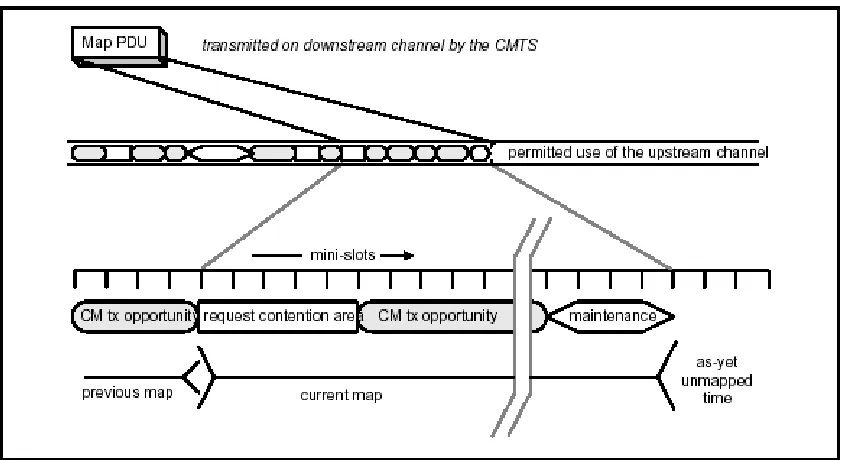
Figure 2.7: Allocation MAP
The allocation MAP message consists of a fixed length header followed by variable number of Information Elements (IEs). Each IE describes allowed usage for a range of mini-slots. Each IE consists of 14 bit SID, 4-bit type code and 14-bit starting offset. SID identifies the service flow that can use the mini-slots.
IE provides an interval in which the CMs are expected to do ranging or power adjustments. Short/Long data grant IE provides a upstream transmission opportunity for a CM. These IEs may be issued in response to a CM request or because of an administrative policy. When these IEs are issued by a CMTS with a grant length of 0, this indicates that a request has been received by CMTS and is pending. Every MAP also contains an ACK time that indicates the latest time, from CMTS initialization, processed in upstream. This is used by the CMs for collision detection.
2.2.5.2 Sending Requests
2.2.5.3 Map Transmission and Timing
MAPs must be transmitted considerably earlier than its effective time. The MAP might be delayed due to propagation delays of downstream channel, Queuing delay within the CMTS or processing delay within the CMs. The number of mini-slots described per MAP
may vary. At a maximum, a MAP is bounded by a maximum limit of 240 Information Elements. Also, a MAP must not describe more than 4096 mini-slots in future. The set of all the MAPs must describe every mini-slot in the upstream channel.
2.2.5.4 Protocol Example
We look at an example to illustrate the interchange between the CM and the CMTS when the CM has data to transmit.
Figure 2.8: Protocol Example
“Description steps:
2. At t2, the CM receives this MAP and scans it for request opportunities. In order to minimize request collisions, it calculates t6 as a random offset based on the Data Backoff Start value in the most recent MAP.
3. At t4, the CM transmits a request for as many mini-slots as needed to accommodate the PDU. Time t4 is chosen based on the ranging offset so that the request will arrive at the CMTS at t6.
4. At t6, the CMTS receives the request and schedules it for service in the next MAP. (The choice of which requests to grant will vary with the class of service requested, any competing requests, and the algorithm used by the CMTS.)
5. At t7, the CMTS transmits a MAP whose effective starting time is t9. Within this MAP, a data grant for the CM will start at t11.
6. At t8, the CM receives the MAP and scans for its data grant.
7. At t10, the CM transmits its data PDU so that it will arrive at the CMTS at t11. Time t10 is calculated from the ranging offset as in step 3.
At Step 3, the request may collide with requests from other CMs and be lost. The CMTS does not directly detect the collision. The CM determines that a collision (or other reception failure) occurred when the next MAP with an ACK time indicating that the request would have been received and processed fails to include an acknowledgment of the request. The CM then performs a back-off algorithm and retries.
pending. So long as the CM is receiving a zero-length grant, it will not issue new requests for that service queue.”
2.2.5.5 Upstream Contention Resolution
The CMs may contend to send request or data PDUs. The contention resolution is based on a truncated binary exponential off, with the initial off window and maximum back-off window controlled by the CMTS. These values are specified as part of the MAP message. Every time a CM wants to transmit in a contention-region, it enters the contention resolution process by setting its internal back-off window to Data Backoff start. The CM selects a random number within this back-off window. CM will defer this random number of contention transmit opportunities. After the transmission, CM waits for a Data Grant or Data Grant pending or Data Acknowledge. Once this is received, the contention phase is complete. If the CM receives a MAP without a Data Grant or Data Grant pending or Data Acknowledge for it and with an ACK time more recent than its time of transmission, then it determines that its request has been lost. The CM increases the back-off window by a factor of two, as long as it is less than maximum back-off window. The CM again selects a random number within its back-off window and repeats the deferring process. The PDU is discarded after 16 retries. If the CM receives a Data Grant or unicast Request while deferring, then it stops the contention resolution process and uses the explicit transmit opportunity.
2.2.6 Quality of Service(QoS)
• Packet Classification & Flow Identification
• Service Flow QoS Scheduling
• Dynamic Service Establishment
• Fragmentation
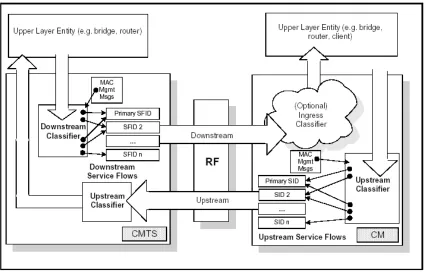
The packets traversing the RF MAC interface are classified into a service flow. A Service Flow is a unidirectional flow of packets that is provided a particular Quality of Service. The CM and the CMTS shape, police and prioritize traffic according to the QoS parameter set defined for the service flow. The QoS parameter set also includes the details of how the CM requests upstream mini-slots and the expected behavior of the upstream scheduler.
Atleast two service-flows are setup for every CM: one for upstream and one for downstream service. The first upstream service flow is also known as the Primary Upstream Service Flow, and is the default service flow for the unclassified upstream traffic.
A service flow is partially characterized by following attributes:
ProvisionedQoSParamSet: This defines the QoS parameters that appear in configuration file and is presented during registration.
AdmittedQoSParamSet: Defines the QoS parameters for which the CMTS and the CM are reserving resources.
ActiveQoSParamSet: The QoS parameters defining the service actually being provided to the service flow. Only an active service flow can forward the packets.
and reference to a service flow. CMTS applies downstream classifiers to the packet it is transmitting and CM applies upstream classifiers to the packets being transmitted on the upstream channel.
Figure 2.9: Classification within the MAC layer
Registration process is used for static configuration of Classifiers and Service Flows. The CM obtains the configuration file from a provisioning server. CM passes this information to the CMTS in a registration request message. CMTS responds with a registration response message, which is acked by the CM to complete the registration process.
Service flows might be created dynamically by either the CM or the CMTS. A three way handshake is used to create these dynamic service flows. Service flow parameters can also be modified dynamically.
2.2.6.1 Upstream Service Flow Scheduling Services
Upstream scheduling services improve the efficiency of the poll/grant process. The CMTS can provide polls and/or grants at appropriate time based on scheduling service and its associated QoS parameters. The basic services comprise:
Unsolicited Grant Service (UGS): This service supports real-time flows that generate fixed
size data packets on a periodic basis, such as Voice over IP. CMTS offers fixed size data grant on a periodic basis to the service flow. This eliminates the overhead and latency of the CM requests. The flow can only use unsolicited data grant and is prohibited from using contention-request or unicast request opportunities. The mandatory service parameters are Grant size, Grants per interval, Nominal grant interval and Tolerated grant jitter.
Real-Time Polling Service (rtPS): This service supports real-time service-flows that
optimum data transport efficiency. The flow is prohibited from using any contention request or request/data opportunities. The mandatory service parameter is Nominal polling interval.
Unsolicited Grant Service With Activity Detection(UGS/AD):
This service supports UGS flows that may become inactive for substantial period of time, such as Voice over IP with silence suppression. CMTS provides unsolicited grant when the flow is active and unicast requests when flow is inactive. The CMTS might detect inactivity by detecting unused grants. The algorithm used to detect inactivity depends on the CMTS implementation. The flow is prohibited from using any contention request or request/data opportunities. The mandatory service parameters are Grant size, Grants per interval, Nominal grant interval and Tolerated grant jitter.
Non-Real-Time Polling Service: This service supports non real-time service-flows that
require variable size data grants on a regular basis, such as high bandwidth FTP. The CMTS might poll on a periodic or non-periodic basis. The flow can also use the contention request or request /data opportunities.
Best Effort Service: This service is for best-effort traffic. The flow can use contention,
request/data opportunities and unsolicited requests opportunities.
2.2.6.2 Fragmentation
CM fragmentation support: Any time fragmentation is enabled and CMTS allocates partial grant to a flow, the CM fills up the partial grant with maximum amount of data taking fragmentation and physical overhead into account. A special fragment header precedes the data. If there is no grant or grant-pending for the flow, then CM sends a piggyback request. If there is no grant or grant-pending within the ACK time of sending a request, the CM back-offs and re-requests bandwidth for untransmitted portion. This process is continued until the CMTS grants request or the retry threshold is exceeded. The remaining portion of the packet is dropped if retry threshold is exceeded. Each fragment sent has a sequence number used by the CMTS to reassemble the frame.
CMTS fragmentation support: CMTS can perform fragmentation in two modes - Multiple Grant mode and Piggyback mode. In Multiple Grant mode, CMTS retains the state of fragmentation and allows multiple partial grants outstanding for any SID. In piggyback mode, the CM sends a piggyback request for the remaining frame. Once the CMTS reassembles the entire frame, it is processed like a normal packet.
2.2.6.3 Concatenation
3. ARCHITECTURE
This chapter presents the design of a high speed data over cable model implemented in Network Simulator - 2 as part of this thesis. The first section provides a brief overview of the NS-2 simulation package. The design of the model is discussed in the next section.
3.1 Network Simulator (NS) Overview
NS is an object-oriented discrete-event simulator used for networking research. NS version 1.0 was developed by the Network Research Group at Lawrence Berkeley National Laboratory. NS development is now a part of the VINT project.
NS is well suited for the simulation of packet-switched networks. There is support for various implementations of TCP, routing, multicast, link layer and MAC protocols.
Figure 3.10: User’s view of NS
the Network component objects are implemented in C++. There is a compiled class hierarchy of objects written in C++ and an interpreted class hierarchy of objects written in OTcl. There is a one-to-one correspondence between a class in the interpreted hierarchy and a class in the compiled hierarchy.
Event Scheduler
An event in NS is a packet with a unique ID, an expiration time and pointer to the object that handles the event. The event scheduler keeps track of the simulation time and fires all the events in the event-list expiring at the current time by invoking their handlers. Network objects communicate with one another by passing packets. This does not consume actual simulation time. If an object wants to simulate the delay in handling a packet, an event can be issued for the packet to expire after ‘delay’ time. The current implementation of the simulation engine is single-threaded without the support of partial execution of events or preemption. Currently four types of event schedulers are supported: simple linked-list, heap, calendar queue and real-time.
Network Components
Figure 3.2: Network Simulator Class Hierarchy
two types of basic network objects: Connector and Classifier. Network objects that have only one output data-path are derived from the Connector class, whereas objects, which can have multiple output data paths, are derived from the Classifier class.
Nodes
The Simulator class provides interfaces to configure, control and operate the simulations. The network topology is created using the standalone classes’ node and link.
Figure 3.3 shows the structure of the node. The function of a node is to receive a packet, process it and forward it to relevant outgoing interfaces. A node is composed of node entry objects, classifier and Agent objects. Each classifier looks at a specific portion of
Figure3.3: Network Simulator Node Structure
Links
Links are characterized by bandwidth and delay. When a duplex-link is created by the user, two simplex links are created in each direction as shown in Figure 3.4.
Figure 3.4: Network Simulator Link Structure
The output queue of the node is a part of the link object. Dequed packets are passed to the
to free their memory. The TTL object updates the Time To Live parameters for each packet received.
Packet
A NS packet is composed of a stack of headers, and an optional data space. (Figure 3.5)
Figure 3.5: Network Simulator Packet Structure
When a simulator object is created, the packet header format is initialized and a stack of all the registered headers is defined and “the offset of each header in the stack is recorded”. Whenever a packet is allocated by an agent, a stack composed of all the registered headers is created irrespective of whether or not a specific header is used. Any header can be accessed in the packet using the corresponding offset of the header in the stack [17].
3.2 Network Simulator – 2 Model
3.2.1 Introduction
implementation of the Media Access Control (MAC) protocol as per the DOCSIS RF interface specifications [18].
3.2.2 Overview of the Model
Figure 3.6 illustrates a sample network topology using the NS-2 package with our model. NS-2 provides a rich set of node types and application models to accurately simulate a realist Internet environment. We introduce two new node types to NS-2: a cable modem node (CM) and a Cable Modem Termination System node (CMTS). The CM node represents a cable modem deployed at a residential or business location. A CM is limited to a single channel and competes with all the other CMs for upstream bandwidth. The CMTS manages the use of the shared upstream channel and has sole use of the single downstream channel. The simulation model will support any number of CMs to be created over a single DOCSIS network, and further any number of DOCSIS networks can be created.
The main features of the DOCSIS MAC protocol have been discussed in chapter 2 of the thesis. The main features of our implementation include:
• Time Division Multiplexing (TDM) for the downstream channel
• Time Division Multiple Access (TDMA) for the upstream channel
• Quality of service features:
• Upstream
Packet classification & flow identification Service flow scheduling services
• Unsolicited grant service (UGS)
• Real-time Polling (rtPS)
• Best-effort Fragmentation Concatenation
Token-bucket Rate control
• Downstream
Packet classification & flow identification Token-bucket Rate control
• Piggybacking
• Payload header suppression
• Support for one upstream and one downstream channel
• Different types of modulation (data rates)
Following features of the DOCSIS specifications are not supported in the model:
• The physical layer is based on a simple model. Only the effective data rate is modeled. Frame level overheads (preamble, RS bits) are included. The S-CDMA access mode is not supported.
• MPEG video packets interleaving with DOCSIS data packets.
• Link security.
A number of tcl scripts have been provided (presented in the next section) to configure the CM and the CMTS nodes. Once the simulation starts, the CMs will send a Registration request message to the CMTS with the details of the service-flows and related QoS parameters. The CMTS responds by assigning a flow-id to each flow. Once all the flows are registered, the CMTS will start sending a MAP and other management messages periodically. The CM nodes will send data on the upstream channel based on the bandwidth allocated to them. Application generators (sources and sinks) must be created in the model to create the data streams that will send over the DOCSIS network. A number of useful simulation statistics are dumped in a file at the end of the simulation.
3.2.3 User-configurable parameters
In this section, various parameters that have to be configured for creating a cable network topology are presented. The tcl scripts to configure these parameters are also discussed.
Upstream Channel Parameters
Following parameters should be configured for the upstream channel:
• Data rate (bits/second)
• Upstream Phy. overhead (bits)
• Propagation delay (microseconds)
Based on these parameters, bytes per mini-slot and number of mini-slots per second for the upstream channel is calculated.
Downstream Channel Parameters
Following parameters should be configured for the downstream channel: Data rate (bits/second)
Downstream Phy. overhead (bits) Propagation delay (microseconds)
The following script is used to create the cable network topology:
set docsis [make-docsislan “node-list” “Upstream-channel parameters” “Downstream
channel parameters” delay LL].
The node-list contains one CMTS node and a list of CM nodes to be created. The User needs to create a CMTS and atleast one CM node to create a basic topology. The delay parameter specifies the delay (in milliseconds) at the Logical link layer.
CM Node Parameters
The users will be able to create multiple upstream and downstream service flows per CM. Atleast one upstream and one downstream service flow must be created per CM.
The script to create an upstream service-flow is:
$docsis configure-upflows $cm-node “Default-flow Upstream-scheduling-type
Concatenation-burst Piggybacking-enabled Grant-size Grant-interval Tolerated-grant-jitter Poll-interval Tolerated-poll-jitter Queue-size Debug”.
The list of upstream service flow parameters includes:
Default-flow: Indicates whether this flow will act as a default upstream-flow for the CM, i.e. all the upstream traffic not matching any flows on a CM will be classified on this flow. A value of 1 indicates default-flow and 0 indicates a non-default flow. There must be one default upstream flow per CM.
Upstream scheduling service type: This specifies the upstream scheduling type for the service-flow. The valid values are 0 for UGS, 1 for rtPS and 2 for Best-effort.
Destination-node and Packet-type: The destination-node and the packet-type are used by the classifier to match the packets to a service-flow. Valid values are all the packet-types currently supported in NS-2.
PHS-type: Indicates the rules to apply Payload header suppression. Valid values are 0 for suppress-all, 1 for suppress TCP/IP, 2 for suppress UDP/IP, 3 for suppress MAC and 4 for No suppression.
Fragmentation-enabled: Indicates whether fragmentation is enabled or not for this flow. A value of 1 indicates enabled and 0 indicates disabled.
Concatenation-enabled: Indicates whether concatenation is enabled or not for this flow. A value of 1 indicates enabled and 0 indicates disabled.
Concatenation-burst: This parameter is only used when concatenation is enabled. It indicates the number of packets that must be concatenated together to form a concatenated frame. It must be greater than 0.
Grant size and grant interval: These parameters are only valid when the upstream scheduling service is UGS. Indicates the grant size (in bytes) that the CMTS must allocate every grant-interval (in sec).
Tolerated-grant-jitter: This parameter is also valid only when the upstream scheduling service is UGS. Indicates the maximum amount of time that the transmission opportunities may be delayed from the nominal periodic schedule.
Poll interval: This parameter is only valid when the upstream scheduling service is rtPS. Indicates how frequently (in seconds) the CMTS must allocate unicast request grant.
Tolerated-poll-jitter: This parameter is also valid only when the upstream scheduling service is rtPS. Indicates the maximum amount of time that the unicast request interval may be delayed from the nominal periodic schedule.
Queue-size: Specifies the queue size (number of packets) for the service-flow queue.
Debug: The Debug parameter specifies whether debug messages for this flow should be written or not in the LOG file. A value of 1 indicates that debugging is ON and 0 indicates OFF.
The script to create a downstream service-flow is:
$docsis configure-downflows $node “Default-flow source-node packet-type PHS-type
rate-control rate token-queuelen bucket-size”
Default-flow: Indicates whether this flow will act as a default downstream-flow for the CM, i.e. all the downstream traffic not matching any flows on a CM will be classified on this flow. A value of 1 indicates default-flow and 0 indicates non-default flow.
Packet-type: The packet-type is used by the classifiers to match the packets to a service-flow. Valid values are all the packet-types currently supported in NS-2.
PHS-type: Indicates the rules to apply Payload header suppression. Valid values are 0 for suppress-all, 1 for suppress TCP/IP, 2 for suppress UDP/IP, 3 for suppress MAC and 4 for No suppression.
Rate-control: Indicates whether rate-control is applied on this flow. A value of 1 indicates enabled and 0 indicates disabled.
Rate (in bits/second): This parameter is only valid if rate-control is enabled. It indicates the maximum downstream traffic rate for the flow.
Token-queuelen: This parameter is only valid if rate-control is enabled. Indicates the maximum queue size used in token-bucket rate-control.
Bucket-size (bits): This parameter is only valid if rate-control is enabled. Indicates the maximum burst that can be sent back to back on this flow.
Besides creating upstream and downstream service-flows, CMs must also be configured with the frequency of ranging messages. The script used is:
$docsis configure-cm $node ranging-message-interval cm-id debug
Ranging message interval: Defines the frequency of ranging messages originating from the CMs (specified in seconds).
cm-id: It is used to uniquely identify a CM when observing LOG messages.
CMTS Node Parameters
There are a number of parameters that need to be configured for the CMTS. The script used to configure the MAP parameters is:
$docsis configure-mapparams $cmts-node “map-time map-frequency
num-management-slots num-contention-num-management-slots backoff-start backoff-end map-lookahead”
Map-time (in seconds): Specifies the time covered by a MAP message. Map-frequency (in seconds): Specifies the frequency of the MAP message.
Num-management-slots: Indicates the number of management slots to be allocated per MAP. Num-contention-slots: Indicates the number of contention slots to be allocated per MAP. Backoff-start: The backoff-start window to be used in the contention phase. Valid value must be a power of 2.
Backoff-end: Specifies the maximum size of backoff window during contention phase. Valid value must be a power of 2.
Map-lookahead: Specifies the maximum number of slots the CMTS can describe over the current map_size. A positive value for this parameter makes the map_time variable.
For configuring other parameters, following script is used:
$docsis configure-mgmtparams $cmts-node “sync-message-interval
ranging-message-interval ucd-message-ranging-message-interval Queue-size”
Sync-message-interval (in seconds): Indicates the frequency of sync messages sent by the CMTS.
Ucd-message-interval (in seconds): Indicates the frequency of ucd messages sent by the CMTS.
Queue-size (in packets): Maximum size of downstream channel queue.
$docsis startregistration: This command starts the simulation of the registration phase.
This must be executed once all the Upstream/Downstream flows have been created for all the CMs and the CMTS has been configured. A complete simulation script has been provided in
Appendix A.
3.2.4 Simulation Statistics
Users will be able to obtain the following statistics from the simulation.
CMTS Node Statistics
The following statistics can be obtained on a periodic basis or at the end of the simulation: Upstream channel bandwidth
Upstream Application load Downstream channel bandwidth Downstream Application load Upstream channel utilization Downstream channel utilization
Total num. of packets received on Upstream Total num. of packets sent on Downstream
Total packets dropped in service-flow queues Total packets dropped
Loss rate
Number of contention requests received Number of piggyback requests received Number of requests granted
Per Service-flow statistics:
Total bytes sent on upstream channel
Total bytes received on downstream channel Total packets dropped
Loss rate
CM Node Statistics
The following statistics can be obtained on a periodic basis or at the end of the simulation: Upstream channel bandwidth
Upstream Application load Downstream channel bandwidth Downstream Application load
Total num. of packets sent on Upstream
Loss rate
Number of contention requests sent Number of piggyback requests sent Avg. Queuing delay
Total num. of first collisions Total num. of collisions Total num. of fragments sent
3.2.5 CM Node Design
In this section, a detailed design of the CM node functionality is presented.
3.2.5.1 Introduction
The CM node represents a cable modem deployed at a residential or business location. The main functionality of the CM node is to pass the packets between the CPE and the CMTS and vice-versa. A number of management messages are exchanged between the CMTS and the CMs for various purposes (Upstream channel usage control, ranging, time synchronization etc). Most of the management message functionality is not implemented in the model, as it is not required in a simulation environment. However, these management messages are generated periodically to create the necessary overhead. In our model, the traffic sources representing the CPE will be attached to the CM node itself.
the packet. A queue is maintained for each service-flow. Depending on the current allocation for that service-flow, the packet may either be queued or sent. For example, if the packet has been classified to a best-effort service flow, then payload header suppression for that service-flow is performed and the allocation table for best-effort service service-flow will be examined. If there is no allocation or grant pending, then a request frame will be sent and the packet will be queued. Later when upstream bandwidth is allocated to this flow, the queued packet will be sent. When a frame arrives at the CM over the downstream channel (i.e., sent by the CMTS), the frame is classified as a Management message or a Data-PDU using the DOCSIS header and then the payload is handled accordingly.
3.2.5.2 Service flow implementation
As discussed earlier, any packet going out of the RF interface of the CM must belong to a service-flow. Users configure the service-flows with their associated parameters through tcl scripts (discussed in section 3.2.3). Each CM must configure atleast two default service-flows: one for upstream and one for downstream.
When the simulation starts, every CM node registers itself to the CMTS by simulating the registration phase. The CMTS allocates a flow-id to each service-flow. The CMTS uses this flow-id to make bandwidth allocations to the service-flows. The major components of a service-flow are -
Queue: A queue is maintained per service-flow. All the packets classified on this service flow are enqued if they cannot be immediately sent.
Allocation-table: The allocation-table maintains the current and the future grants for this service flow. This table is updated whenever a MAP message is received on the downstream channel. Based on the type of grant, either DOCSIS frames, contention request or unicast request will be sent on the upstream channel.
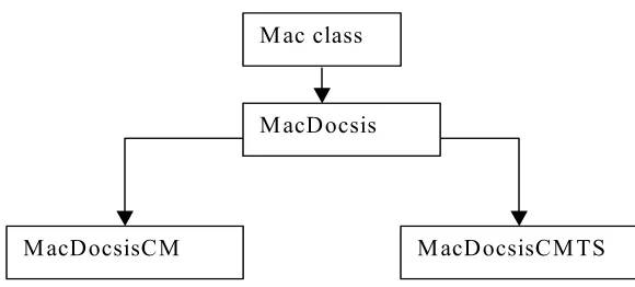
Finite state machine: The model supports three types of upstream scheduling services - Unsolicited Grant Service, Real-time Polling and Best-effort. The type of the scheduling service per service flow is configured by the user and is made known to the CMTS via the registration message. The CMTS implements these service-types by its bandwidth allocation algorithm. At the CM node, depending on the service type, a finite state machine controls all interactions of the service-flow for upstream transmissions. These finite state machines have been implemented using a Procedure-driven approach i.e. one function for each input state. When an event occurs, depending on the current state, the proper function is called to process the input event and update the state variable.
The finite state machine for the three service types is presented in the next section.
3.2.5.3 Unsolicited Grant Service
The following states have been defined:
Decision: In this temporary state, the allocation-table for the service flow is examined for grants.
Wait_For_MAP: This state represents that a MAP with new allocations is awaited. To_Send: There is a pending transmission of a packet.
The following events have been defined:
Packet: An upper-layer or management packet has been classified on the service-flow to be sent over the upstream channel.
MAP: A MAP management message has been received on the downstream channel with new allocations.
Send_Timer: The Send Timer has expired. Send_Pkt: Indicates that a packet has to be sent.
PACKET MAP PACKET MAP
1a 1b 4c 4d
SEND TIMER 4b 4b
1a 4b 2a, 4a
3a, 4a
2a
3a 3b
PACKET MAP
TO_SEND
DECISION IDLE
WAIT-FOR-MAP
Figure 3.7: FSM for UGS
1. Idle state:
a. Event: Packet arrival
Action: The DOCSIS header is added and the packet pointer is stored in the variable current_pkt.
New state: Decision state with event Packet arrival. b. Event: MAP arrival
Action: Update the allocation-table for this flow. New state: No state change.
2. Decision state:
a. Event: Packet arrival
Action: Check the allocation table. If no data grants exist the state
Event Send_Pkt.
New state: Depends upon action routine. 3. Wait_For_MAP state:
a. Event: MAP arrival
Action: If there is a data-grant for this flow, then transition to To_Send state with event Send_Pkt. Else, there is no transition.
New state: Depends upon action routine. b. Event: Packet arrival
Action: Add the DOCSIS headers and enque the packet. New state: No state change.
4. To_Send state:
a. Event: Send_Pkt
Action: The Send timer is started. It is set to expire when the data grant begins.
New state: No state change. b. Event: Send_Timer
Action: Send the curr_pkt over the upstream channel. If the queue has become empty, then transition to Idle state.
Else, a packet is dequed and stored in curr-pkt. The state is changed to Decision state with event packet arrival.
New state: Depends upon action routine. c. Event: Packet arrival
New state: No state change. d. Event: MAP arrival
Action: Update the allocation-table for the flow. New state: No state change.
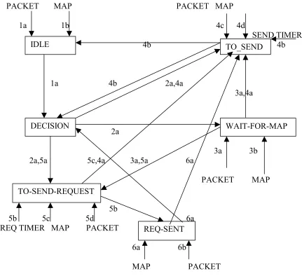
3.2.5.4 Real-time Polling
All the states and events described in the UGS section have the same meaning for this finite state machine. In addition, following states and events are defined:
States:
To_Send_Req: Indicates that there is a unicast request grant in the future. Req_Sent: Indicates that a request has been sent for data grants.
Events:
Request_Timer: The Request timer has expired.
Send_Req: Indicates that a unicast request has to be sent in the future.
The state machine is depicted in Figure 3.8. A detailed description follows: 1. Idle state:
a. Event: Packet arrival
Action: The DOCSIS header is added and the packet pointer is stored in the variable current_pkt.
New state: Decision state with event Packet arrival. b. Event: MAP arrival
New state: No state change. 2. Decision state:
a. Event: Packet arrival
Action: The allocation table is checked. If there are no data/unicast- request grants, then the new state is Wait_For_MAP. If there is a data- grant in the future, then transition to state To_Send with event Send_Pkt. Else, if there is unicast-request grant in the future, then transition to To_Send_Req with event Send_Req.
New state: Depends upon action routine. 3. Wait_For_MAP state:
a. Event: MAP arrival
Action: The allocation-table is updated. If there is a unicast data grant, then transition to To_Send state with event Send_Pkt. If there is a unicast request grant, then transition to To_Send_Req with event Send_Req. Else, there is no transition.
PACKET MAP PACKET MAP
1a 1b 4c 4d
SEND TIMER 4b 4b
1a 4b 2a,4a
3a,4a
2a
3a 3b 2a,5a 5c,4a 3a,5a 6a
PACKET MAP
5b
5b 5c 5d 6a REQ TIMER MAP PACKET
6a 6b
MAP PACKET
TO_SEND
DECISION IDLE
WAIT-FOR-MAP
TO-SEND-REQUEST
REQ-SENT
Figure 3.8: FSM for rtPS
b. Event: Packet arrival
Action: The DOCSIS header is added and the packet pointer is stored in the variable current_pkt.
New state: No state change. 4. To_Send state:
Action: The Send timer is started. It is set to expire when the data grant begins.
New state: No state change. b. Event: Send_Timer
Action: Send the curr_pkt over the upstream channel. If the queue has become empty, then transition to Idle state. Else, a packet is dequed and stored in curr-pkt. The state is changed to Decision state with event packet arrival.
New state: Depends upon action routine. c. Event: Packet arrival
Action: Add the DOCSIS headers and enque the packet. New state: No state change.
d. Event: MAP arrival
Action: Update the allocation-table for the flow. New state: No state change.
5. To_Send_Req state:
a. Event: Send_Req
Action: Set the Req timer to expire when the allocation starts for sending Unicast Request frame.
New state: No state change. b. Event: Req timer expires
c. Event: MAP arrival
Action: The allocation table is updated. If there is a unicast data grant in the MAP, then the Req timer is stopped and state is transitioned to To_Send with event Send_Pkt. Else, there is no transition.
New state: Depends upon action routine. d. Event: Packet arrival
Action: The DOCSIS header is added and the packet pointer is stored in the variable current_pkt.
New state: No state change. 6. Req_Sent state:
a. Event: MAP arrival
Action: Update the Allocation-table. If there is a unicast data grant, then transition to To_Send with event Send_Pkt. If there is no data grant pending indicator and the Ack time of the MAP is greater than the time at which the request was sent, then transition to Decision state with event Send_Pkt. Else, there is no state change.
New state: Depends upon action routine. b. Event: Packet arrival
3.2.5.5 Best-effort Service
In addition to the states and events used in UGS and rtPS section, following new states and events have been defined:
States:
Contention: This state implements the binary-exponential back-off algorithm for contention. Events:
Unicast_Req: Indicates that a unicast request grant is available for this service flow. Contention_Req: Indicates that a contention request grant is available for this service flow. Contention_On: Indicates that the contention phase should be entered.
Contention_Bkoff: Indicates that back-off is required as the contention request was lost.
The state machine is shown in Figure 3.9. The detailed description follows: 1. Idle state:
a. Event: Packet arrival
Action : The DOCSIS header is added and the packet pointer is stored in the variable current_pkt.
New state: Decision state with event Packet arrival. b. Event: MAP arrival
Action: Update the allocation table for this flow. New state: No state change.
2. Decision state: