Development of Multi Level Inverter for
Speed Control of Three Phase Induction
Motor by Using PWM technique
Jigneshkumar Varodiya1, Pratik B. Patel2
P.G. Student, Department of Electrical Engineering, MGITER Engineering College, Navsari, Gujarat, India1 Assistant Professor, Department of Electrical Engineering, MGITER Engineering College, Navsari, Gujarat, India2
ABSTRACT: Today’s Modern Technology Most of the Industrial Drives Use Ac Induction Motor Because These Motor Are Rugged, Reliable and Higher Efficiency or Relatively in Expansive. Induction Motor Are Mainly Used for Constant Speed Control Application in Traction Transportation and Agriculture. Heavy to Medium Industry and Domestic Application like Water Pump. Because Of Unavailability of the Variable Frequency Control Supply Voltage But Many Applications Need Variable Speed of Operation Present Day. The Induction Motor Drive With Voltage Source Inverter And Current Source Inverter The Recent Advancement In Power Electronics Has Initiated To Improve The Level Of Inverter Instead Increasing The Size Of Filter The Total Harmonics Distroration Of The Classical Inverter Is Very High.
KEYWORDS: PWM Technique, SPWM, SVPWM, Speed Control of Three Phase Induction Motor. THD losses.
I. INTRODUCTION
Electrical Energy already constitutes more than 30 % of all energy usage on Earth. And this is set to rise in the coming years. Its massive popularity has been caused by its efficiency of use, ease of transportation, ease of generation, and environment-friendliness. Part of the total electrical energy production is sued to produce heat, light, in electrolysis, arc-furnaces, domestic heating etc. Another large part of the electrical energy production is used to be converted into mechanical energy via different kinds of electric motors- DC Motors, Synchronous Motors and Induction Motors. Induction Motors are often termed the “Workhorse of the Industry”. This is because it is one of the most widely used motors in the world. It is used in transportation and industries, and also in household appliances, and laboratories. The major reasons behind the popularity of the Induction Motors are:
i. Induction Motors are cheap compared to DC and Synchronous Motors. In this age of competition, this is a prime requirement for any machine. Due to its economy of procurement, installation and use, the Induction Motor is usually the first choice for an operation.
ii. Squirrel-Cage Induction Motors are very rugged in construction. There robustness enables them to be used in all kinds of environments and for long durations of time.
Another major advantage of the Induction Motor over other motors is the ease with which its speed can be controlled. Different applications require different optimum speeds for the motor to run at. Speed control is a necessity in Induction Motors because of the following factors:
1) It ensures smooth operation.
2) It provides torque control and acceleration control.
3) Different processes require the motor to run at different speeds. 4) It compensates for fluctuating process parameters.
5) During installation, slow running of the motors is required.
6) All these factors present a strong case for the implementation of speed control or variable speed drives in Induction Motors.
II. PWMADVANTAGES&DISADVANTAGES
The space-vector PWM technique is used to produce the switching control signals to be applied to the three-phase inverter. The SVPWM inverter is used to offer 15% increase in the dc link voltage utilization and low output harmonic distortions compared with the conventional sinusoidal PWM inverter. The control strategy of the SVPWM inverter is the voltage/frequency control method which is based on the space-vector modulation technique. For constant torque output, the air gap flux in the motor is maintained constant by operating on a constant voltage/frequency supply. However, the analysis assumes negligible winding resistance, where, in practical, at low frequencies the resistive voltage drop becomes significant compared with the induced voltage. This voltage drop causes a reduction in the air gap flux and motor torque. In order to maintain the low-speed torque, the voltage/frequency control method is used for controlling the speed of PMSM with performance accuracy.
Advantages of PWM
• average value proportional to duty cycle, D
• low power used in transistors used to switch the signal
• fast switching possible due to MOSFETS and power transistors at speeds in excess of 100 kHz
• digital signal is resistant to noise
• less heat dissipated versus using resistors for intermediate voltage values Disadvantages of PWM
• Cost
• Complexity of circuit
• Radio Frequency Interference
• Voltage spikes
• Electromagnetic noise. Applications of PWM
• In the past, motors were controlled at intermediate speed by using resistors to lower delivered power
• Electric stove heater
• Induction motor speed control
• Lamp dimmers circuit
• Induction heating
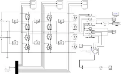
III.SIMULATION CIRCUIT SPWM OPEN LOOP IN INDUCTION MOTOR
In the help of mat lab simulation below figure no 3.0 shows multi-level inverter with diode clamping circuit and spwm technique to use simulation done in open loop system, asynchronous motor used in 5.4Hp by default in matlab similarly figure 3.1to 3.3 various wave form output side in open loop simulation.
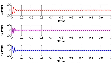
Fig No.3.2 open loop simulation current in RY-YB-RB Amp
Open loop simulation current waveform in without any close loop circuit as well as phase to Phase current shown above figure no 3.2 in open loop simulation.
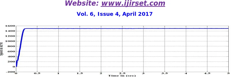
Fig No.3.3 open loop simulation speed waveform in RPM
In the open loop simulation above figure no 3.3 shows speed RPM in rotor side in an induction motor with help of matlab simulation in spwm technique used.
0 0.1 0.2 0.3 0.4 0.5 0.6 0.7 0.8 0.9 1 -100 0 100
Ti me
C
u
r
r
e
n
t
0 0.1 0.2 0.3 0.4 0.5 0.6 0.7 0.8 0.9 1 -100 0 100
Ti me
C
u
r
r
e
n
t
0 0.1 0.2 0.3 0.4 0.5 0.6 0.7 0.8 0.9 1 -100 0 100
Ti me
C
u
r
r
e
n
t
0 0.1 0.2 0.3 0.4 0.5 0.6 0.7 0.8 0.9 1
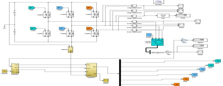
IV.SIMULATION CIRCUIT SVPWM CLOSE LOOP IN INDUCTION MOTOR
In the industry as well as commercial sector wide range of three phase inductor used in automatic speed control as per our requirement in various application purpose, now help of matlab software designed close loop simulation by using SVPWM methods because space vector method very efficient use DC link voltage in the inverter side and lower harmonic THD losses provide compare to other methods in practical development hardware purpose.In the matlab simulation close loop simulation done in the available rating in matlab library, generally done SVPWM Designed in subsystem in the various sector in as per our requirement in application purpose.
Fig No 4.0 Block diagram close loop simulation diagram
Fig 4.2 R-Y-B Reference voltage in close loop system in SVPWM Compare to vector voltage in various sector
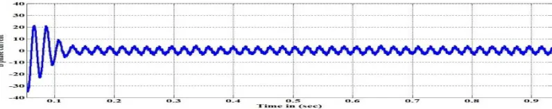
Fig 4.3 phase to phase Current in close loop simulation in SVPWM methods line current R phase.
Fig 4.4 phase to phase Current in close loop simulation in SVPWM methods line current Y phase.
Fig.4.6 close loop simulation speed waveform in RPM In Rotor side.
V. EXPERIMENTALRESULTS
Table 1 Open loop simulation observation table
In the fig no 3.0 shows basic arrangement in open loop simulation done in Spwm methods and Table no 01 shows open loop simulation voltage current torque and speed reading various operating torque given in motor table no 01 shows torque and current increase similarly speed of motor will be decreased in various step that means no any close loop path available for speed sensing in rotor side.
Table 2 Close loop simulation observation table
Sr.No Voltage (Volts)
Current (Amp)
Frequency(Hz) Torque Speed in RPM 01 400.03 4.26 48.17 0 1445 02 400.03 4.39 47.94 1 1438 03 400.03 4.57 47.56 2 1427 04 400.01 4.83 47.03 3 1419 05 400.01 5.10 46.98 4 1409 06 400.00 5.46 46.70 5 1401 07 400.00 5.63 46.52 5.5 1391
In the fig no 4.0 shows basic arrangement in close loop simulation done in SVPWM methods and Table no 04 shows Sr.No Voltage
(Volts)
Current (Amp)
Torque Speed in RPM
VI. CONCLUSION
The modelling of multilevel inverter fed induction motor drive was done and simulated using Simulink. The total harmonic distortion is very low compared to that of classical inverter. The simulation result shows that the harmonics have been reduced considerably. The multilevel inverter fed induction motor system has been successfully simulated and the results of voltage waveforms.
REFERENCES
[1] B. Urmila, R. Sheba Rani, B. Subbarayudu and L. Raja Sekhar Goud, "Three-level inverter fed induction motor," IEEE-International Conference On Advances In Engineering, Science And Management (ICAESM -2012), Nagapattinam, Tamil Nadu, pp. 100-104, 2012.
[2] F. A. Samman, T. Waris, T. D. Anugerah and M. N. Z. Mide, "Three-phase inverter using microcontroller for speed control application on induction motor," 2014 Makassar International Conference on Electrical Engineering and Informatics (MICEEI), Makassar,pp.28-32.doi:10.1109/MICEEI.2014.7067304, 2014.
[3] R. V. Thomas, Rakesh E, J. Jacob and Chitra A, "Identification of optimal SVPWM technique for diode clamped multilevel inverter based induction motor drive," 2015 IEEE International Conference on Electrical, Computer and Communication Technologies (ICECCT), Coimbatore, , pp. 1-6, 2015.
ACKNOWLEDGMENT
It is with great pleasure that I acknowledge my sincere thanks to Prof.Pratik B Patel, Professor, Department of Electrical Engineering, MGITER College of Engineering, Navsari, Gujarat, India.
BIOGRAPHY
JigneshkumarVarodiya pursuing M.E in Electrical Engineering from GTU Gujarat in 2015-2017,B.Tech in Electrical Engineering from the Stani memorial College Engineering & Technology in Jaipur 2014, His areas of scientific interest are Power system protection, AC/DC Drives, Traction (OHE) designed, HV & LV Switchgear. [email protected]