Lossless (Reversible) Digital Image Encoding
Compression Techniques using ARM9
G.Phani Kumar1, Vishweshwar Rao2
M. Tech Student, Department of Electronics & Communication Engineering, Lenora Engineering College,
Rampachodavarm, A.P, India1
Associate Professor, Department of Computer Engineering, Electronics & Communication Engineering, Lenora
Engineering College, Rampachodavarm, A.P, India
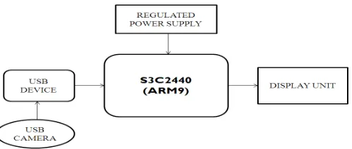
ABSTRACT: There are numerous applications of image processing, such as satellite imaging, medical imaging, and video where the image size or image stream size is too large and requires a large amount of storage space or high bandwidth for communication in its original form. Image compression techniques can be used effectively in such applications. Lossless (reversible) image compression techniques preserve the information so that exact reconstruction of the image is possible from the compressed data. In this paper we survey existing coding and lossless compression schemes and also provide an experimental evaluation of various state of the art lossless compression algorithms that have been reported in the literature. The experimental evaluation is done using MINI 2440(ARM9) board with camera and Embedded Linux and displays it on TFT touch screen display.
The camera will capture the image and send it to controller. The controller will save the image in jpg format. Also it loads the same image into another IPL (Image Processing Language) image. By using jpg compression factor set the image quality. Compressing and decompressing image is also same by using jpg compression factor.
KEYWORDS: ARM9, USB Camera, Display, Lossless.
I. INTRODUCTION
Evolution of embedded systems recently has a strong trend towards application-specific, single-chip solutions. In the domain of embedded system the ARM processor core is a leading RISC processor architecture. It supports a unique feature of code size reduction. Image Compression is a method, which reduces the size of the data to reduce the amount of space required to store the data. The Discrete cosine transform (DCT) is a method for transforms a signal or image from spatial domain to frequency component. It is a widely used technique in image compression. In this paper, we are proposing a lossless discrete cosine transform (DCT) compression technique for two-dimensional image using ARM9 Processor. In the several scenarios, the utilization of the proposed technique for image compression resulted in comparable or better performance, when compared to the different modes of the lossless JPEG standard
II. IMAGECOMPRESSION
Image compression is the application of Data compression on digital images. The objective of image compression is to reduce redundancy of the image data in order to store or transmit data in an efficient form. The image compression techniques are broadly classified into two categories depending whether the compressed image is an exact replica of the original image or not. These are: Lossless technique, Lossy technique. By using lossy method which does not allow the exact original data to be reconstructed from the compressed data. And the advantage of lossy methods over lossless methods is that in some cases a lossy method can produce a much smaller compressed file than any known lossless method, while still meeting the requirements of the application. Another advantage is when a user acquires a lossily compressed file the download time will be reduced.
In lossy compression it includes different algorithms to compress the image. One of technique is DCT (Discrete Cosine Transform).
III.TYPESOFIMAGECOMPRESSION
A. LOSSLESS COMPRESSION TECHNIQUE
In lossless compression techniques, the original image can be perfectly recovered from the compressed (encoded) image. These are also called noiseless since they do not add noise to the signal (image). It is also known as entropy coding since it use statistics/decomposition techniques to eliminate/minimize redundancy. Lossless compression is used only for a few applications with stringent requirements such as medical imaging. Following techniques are included in lossless compression:
Run length encoding
Huffman encoding
LZW coding
B. LOSSLESS COMPRESSION TECHNIQUE
Lossy schemes provide much higher compression ratios than lossless schemes. Lossy schemes are widely used since the quality of the reconstructed images is adequate for most applications .By this scheme, the decompressed image is not identical to the original image, but reasonably close to it .In this prediction – transformation – decomposition process is completely reversible .The quantization process results in loss of information. The entropy coding after the quantization step, however, is lossless. The decoding is a reverse process. Firstly, entropy decoding is applied to compressed data to get the quantized data. Secondly, dequantization is applied to it & finally the inverse transformation to get the reconstructed image. Major performance considerations of a lossy compression scheme include: Compression ratio, Signal - to – noise ratio, Speed of encoding & decoding. Lossy compression techniques includes following schemes:
Linear predictive coding
Fractal compression
Transform coding
Vector quantization
Wavelet compression
IV.DCTANDINVERSEDCT
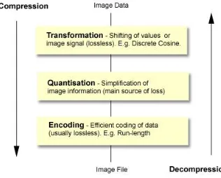
The diagram below shows the key steps in a lossy image compression. These steps are reversed when the image is displayed (decompressed). In contrast, a lossless compression will usually just have the encoding/decoding step.
Fig. 2.Encoding data in tree representation
A. PROPOSED DCT ALGORITHM:
The following is a general overview of the JPEG process.
The image is broken into 8x8 blocks of pixels.
Working from left to right, top to bottom, the DCT is applied to each block.
Each block is compressed through quantization.
The array of compressed blocks that constitute the image is stored in a drastically
Reduced amount of space.
When desired, the image is reconstructed through decompression, a process that uses the inverse Discrete Cosine Transform (IDCT).
The forward 2D_DCT and inverse 2D-DCT transformation is given by the following equation:
B. QUANTIZATION
compression takes place.DCT really does not compress the image because it is almost lossless. Quantization makes use of the fact that higher frequency components are less important than low frequency components. It allows varying levels of image compression and quality through selection of specific quantization matrices. Thus quality levels ranging from 1 to 100 can be selected, where 1 gives the poorest image quality and highest compression, while 100 gives the best quality and lowest compression. As a result quality to compression ratio can be selected to meet different needs.JPEG committee suggests matrix with quality level 50 as standard matrix. For obtaining Quantization matrices with other quality levels, scalar multiplications of standard quantization matrix are used. Quantization is achieved by dividing transformed image matrix by the quantization matrix used. Values of the resultant matrix are
Then rounded off. In the resultant matrix coefficients situated near the upper left corner have lower frequencies .Human eye is more sensitive to lower frequencies .Higher frequencies are discarded. Lower frequencies are used to reconstruct the image.
C. ENTROPY ENCODING:
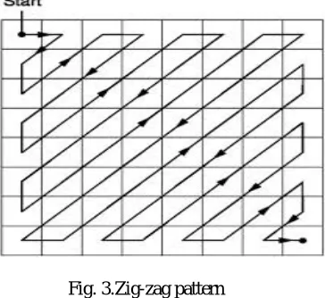
After quantization, most of the high frequency coefficients are zeros. To exploit the number of zeros, a zig-zag scan of the matrix is used yielding to long string of zeros. Once a block has been converted to a spectrum and quantized, the JPEG compression algorithm then takes the result and converts it into a one dimensional linear array, or vector of 64 values, performing a zig-zag scan by selecting the elements in the numerical order indicated by the numbers in the grid below:
Fig. 3.Zig-zag pattern
This places the elements of the coefficient block in a reasonable order of increasing frequency. Since the higher frequencies are more likely to be zero after quantization, this tends to group zero values in the high end of the vector.
D. HUFFMAN CODING:
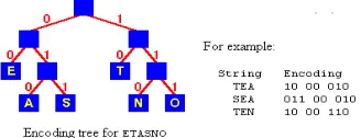
probable characters, and repeating this process until there is only one character remaining. A code tree is thus generated and the Huffman code is obtained from the labeling of the code tree.
An encoding for each character is found by following the tree from the route to the character in the leaf: the encoding is the string of symbols on each branch followed.
Fig. 4.Encoding data in tree representation
Images can be compressed by using different algorithms. Compression techniques can be divided into two types. There is lossless and lossy compression. When comparing the lossless with lossy compression, lossy gives more advantages in some cases. By using lossy method which does not allow the exact original data to be reconstructed from the compressed data. The advantage of lossy methods over lossless methods is that in some cases a lossy method can produce a much smaller compressed file than any known lossless method, while still meeting the requirements of the application. Another advantage is when a user acquires a lossily compressed file the download time will be reduced. When considering these features lossy technique can be used for compressing the images. In lossy technique different algorithms can be used for compressing the images. One of the algorithms can be explained in the above that is DCT (Discrete Cosine Transform).
In DCT algorithm it includes different steps for compressing the image. There are transformation, quantization and entropy coding. The disadvantage of compressing the image using algorithm, the number of steps is increased in the program. If the steps are increased in the program, the memory usage also increased. So the execution time also increased. The above disadvantages can be reduced by using openCV software in place of algorithms. In that the number of steps in the program can be decreases and memory space also reduced, so execution time also reduced. In this project the software program can be loaded into ARM9 processor for compressing the images.
V. HARDWARE&DESIGN
In this project, the different hardware components such as S3C2440, ARM architecture, serial communication devices like RS 232 and Max 232, USB webcam, touch screen display are used and each of them are explained below.
A. SC2440 MICRO-CONTROLLER:
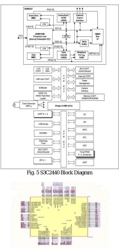
The S3C2440X is a 16/32-bit RISC microprocessor, which is designed to provide a cost-effective, low-power capabilities, high performance Application Processor solution for mobile phones and general applications. To provide optimized H/W performance for the 2.5G & 3G communication services, the S3C2440X adopts 64/32-bit internal bus architecture. The 64/32-bit internal bus architecture is composed of AXI, AHB and APB buses. It also includes many powerful hardware accelerators for tasks such as motion video processing, audio processing, 2D graphics, display manipulation and scaling. An integrated Multi Format Codec (MFC) supports encoding and decoding of MPEG4/H.263/H.264 and decoding of VC1. This H/W Encoder/Decoder supports real-time video conferencing and TV out for both NTSC and PAL mode. Graphic 3D (hereinafter 3D Engine) is 3D Graphics Hardware Accelerator which can accelerate OpenGL ES 1.1 & 2.0 rendering.
mobile DDR, DDR, mobile SDRAM and SDRAM. The Flash/ROM port supports NOR-Flash, NAND-Flash, One NAND, CF and ROM type external memory.
To reduce total system cost and enhance overall functionality, the S3C2440X includes many hardware peripherals such as a Camera Interface, TFT 24-bit true color LCD controller, System Manager (power management & etc.), 4-channel UART, 32-channel DMA, 5-channel 32bit Timers with 2PWM output, General Purpose I/O Ports, I2S-Bus interface, I2C-BUS interface,USB Host, USB OTG Device operating at high speed (480Mbps), 3-channel SD/MMC Host Controller and PLLs for clock generation.
Fig. 5 S3C2440 Block Diagram
A.FEATURES:
The features of S3C2440X RISC Microprocessor include:
The ARM1176JZF-S based CPU subsystem with Java acceleration engine and 16KB/16KB I/D Cache and 16KB/16KB I/D TCM.
533MHz at 1.1V and 667MHz at 1.2V respectively.
8-bit ITU 601/656 Camera interface up to 4M pixel for scaled and 16M pixel for un scaled resolution.
2D graphics acceleration with BitBlit and rotation.
1/2/4bpp Palletized or 16bpp/24bpp Non-Palletized Color-TFT.
Port USB 2.0 OTG supporting high speed as Device (480Mbps, on-chip transceiver).
Port USB 1.1 Host supporting full speed (12Mbps, on-chip transceiver).
Real time clock, PLL, timer with PWM and watch dog timer.
Memory Subsystem:
- SRAM/ROM/NOR flash Interface with x8 or x16 data bus. - Muxed One NAND Interface with x16 data bus.
- NAND Flash Interface with x8 data bus. - SDRAM Interface with x32(Port1) data bus. - Mobile SDRAM Interface with x32(Port1) data bus. - DDR Interface with x32(Port1) data bus.
- Mobile DDR Interface with x32(Port1) data bus.
High bandwidth Memory Matrix subsystem.
Two independent external memory ports (1 SROM port and 1 DRAM ports).
VI.MULTIMEDIAACCELERATIONS
The S3C2440X microprocessor provides the following Multimedia Acceleration features:
A. FEATURES:
ITU-R 601/ITU-R 656 format input support. 8-bit input is supported.
Both progressive and interlaced input are supported.
Camera input resolution up to 4096x4096 in YCbCr 4:2:2 formats:
- 4096x4096 input resolution assumes the hardware down-scaling units will be bypass. - Up to 2048x2048 input resolution can optionally be input to the hardware down-scaling unit.
Resolution down-scaling hardware support for input resolutions up to 2048x2048.
Codec/Preview output image generation (RGB 16/18/24-bit format and YCbCr 4:2:0/4:2:2 formats).
Image windowing and digital zoom-in function.
Image mirror and rotation supports Y-mirror, X-mirror, 90’, 180’ and 270’ rotation.
H/W Color Space Conversion.
LCD controller direct path supported in MSDMA.
Image effect supported.
JPEGCODING:
Compression/decompression up to UXGA size.
Encoding format: YCbCr 4:2:2 / RGB565.
B. DISPLAY CONTROL:
The S3C2440X microprocessor provides the following Display Control features:
C. TFT LCD INTERFACE:
1/2/4/8bpp Palletized or 16/18/24-bpp Non-Palletized Color-TFF supports.
Typical actual screen size: 640 x 480, 320 x 240, 800 x 480.
Maximum 16M virtual screen size.
Real-time overlay plane multiplexing.
D. USB SUPPORT:
The S3C2440X microprocessor provides the following USB Support features:
E. USB OTG 2.0: USB OTG 2.0 High Speed:
Complies with the On-The-Go Supplement to the USB 2.0 Specification (Revision 1.0a).
Supports high speed (480Mbps), full speed (12Mbps, Device only), low speed (1.5Mbps, Host only).
Configures as USB 1.1 full/low speed DRD (Dual-Role Device), Host-only or Device only Controller.
F. USB HOST:
2-port USB Host.
Complies with OHCI Rev. 1.0.
Compatible with the USB Specification version 1.1.
G. SERIAL COMMUNICATION:
The S3C2440X microprocessor provides the following Serial Communication features:
H. UART:
4-channel UART with DMA-based or interrupt-based operation.
Supports 5-bit, 6-bit, 7-bit, or 8-bit serial data transmit/receive.
Programmable baud rate.
Non-integer clock divides in Baud clock generation.
I. SYSTEM OPERATING FREQUENICES:
The S3C2440X microprocessor provides the following System Operation Frequencies features:
ARM1176JZF-S core clock rate maximum is [email protected] V, [email protected] (VDDarm).
System operating clock generation
- Three on-chip PLLs, APLL, MPLL & EPLL.
- APLL generates an independent ARM operating clock. - MPLL generates the system reference clock.
- EPLL generates clocks for peripheral IPs.
VII. POWERMANAGEMENT Clock-off control for individual components.
Various power-down modes are available such as Idle, Stop and Sleep mode.
Wake-up by one of external interrupts or by various interrupt sources.
VIII. ELECTRICALCHARACTERSTIC
Operating Conditions
- Memory Port 0(VDDM0) : 1.8/2.5V/3.3V. - Memory Port1 (VDDM1) : 1.8/2.5V. - External I/O Interface: 1.8/2.5/3.3V.
Operational Frequency(VDDarm):
- 533MHz@ 1.1 V. - 667Mhz@ 1.2V.
IX.CONCLUSION
The project “Lossless (reversible) digital image encoding compression techniques using ARM9” has been successfully designed and tested. It has been developed by integrating features of all the hardware components and software used. Presence of every module has been reasoned out and placed carefully thus contributing to the best working of the unit. Secondly, using highly advanced ARM9 board and with the help of growing technology the project has been successfully implemented.
X. FUTURESCOPE
In our application we are using Jpg compression factor to compress image and display the image and image size on display unit but while compressing the image internally size of image is reduced as size reduces quality of image will also reduces so to overcome this limitation in future we can use Lossless compression technique.
Lossless compression involves with compressing data which, when decompressed, will be an exact replica of the original data. This is the case when binary data such as executables, documents etc. are compressed. They need to be exactly reproduced when decompressed. On the other hand, images (and music too) need not be reproduced 'exactly'. An approximation of the original image is enough for most purposes, as long as the error between the original and the compressed image is tolerable.
REFERENCES
[1] An Li and XuemeiXu, The video real-time transmission system based on ARMll. Computer Systems and Applications. l9 (l l) l5-18.
[2] Information on http://ftp3.itu. int/avarch/jvt- site/2003_03_Pattay a/JV1"-G050rl .zip May 2003.
[3] EMBEDDED LINUX C LANGUAGE app;ication programming, huaqingyanjian embedded training center, posts & telecom press,
aug,2007.
[4] Dai li,”implemention of usb camera image capturing based on video4linux‟, unpublished.
[5] caishijie, digital compression and coding of continous-tone still images, Nanjing university press, 1995.
[6] Alan bovik hand image and video processing, publishing house of electronics industry,2006.
[7] Yu-Lun Huang and Jwu-Sheng Hu,” A Teaching Laboratory and Course Programs for Embedded Software Design”, iCEER-2005.
[8] www.arm.com
[9] Rishi Bhardwaj, Phillip Reames, Russell Greenspan Vijay Srinivas Nori, ErcanUcan” A Choices Hypervisor on the ARM architecture”,
2003.
[10] JPEG Technical Specification, Adobe Developer Support year1992.
[11] “INFORMATION TECHNOLOGY JPEG 2000 IMAGE CODING SYSTEM”, JPEG 2000 FINAL COMMITTEE DRAFT VERSION 1.0,
16 MARCH 2000.
[12] Bart Weuts, “Software for ARM Processors and AMBA Methodology-based Systems”, Volume 3, Number 4, 2004.
[13] J,Weinberger and GadielSeroussi,”Lossless Image compression Algorithm principles and standardization. The loco –I into JPEG-LS“.
[14] Kai-Yuan Jan*, Chih-Bin Fan, An-Chao Kuo, Wen-Chi Yen and Youn-Long Lin,” A platform based SOC design methodology and its
application in image compression”, Int. J. Embedded Systems, Vol. 1, Nos. 1/2, 2005 23.
[15] Dongdong Fu, Yun Q. Shi, Wei Su,” A generalized Benford‟s law for JPEG coefficients and its applications in image forensics”, Newark,
NJ 07102, USA.
[16] Bart Weuts, “Software for ARM Processors and AMBA Methodology-based Systems”, Volume 3, Number 4, 2004.
[17] Gregory K. Wallace,” The JPEG Still Picture Compression Standard”, IEEE 1991.
[18] Gunnar Braun ,AchimNohl, Andreas Weiferink ,”Processor/ Memory Co-Exploration on Multiple Abstraction Levels”,IEEE 2003.
[19] www.cs.vcsd.edu/classes/spo2/cse29/e/slides/armlect.pdf.