Vibration Analysis of Composite Reinforced
B- Pillar used in Automobiles
Sushrut Joglekar1, B. D. Patil 2
P.G. Student, Department of Mechanical Engineering, TSSM’s PVPIT, Bavdhan, Pune, Maharashtra, India1
Professor, Department of Mechanical Engineering, TSSM’s PVPIT, Bavdhan, Pune, Maharashtra, India2
ABSTRACT: In this paper a modal analysis is performed on B Pillar of an automobile to obtain its dynamic characteristic by subjecting it to the boundary conditions. The prediction of the dynamic properties of the chassis is great significant to determine the natural frequencies of the structure. In order to avoid resonance, value operating frequency must lower than natural frequency of the chassis. Finally, the modifications of the B Pillar model are proposed to reduce the vibration, improve the strength, and optimize the weight of the chassis.
KEYWORDS:B Pillar, Modal Analysis, Resonance, Natural frequencies, Glass Fibre, Aluminium B390.
I. INTRODUCTION
Global car body stiffness is an important design attribute in vehicle design. Therefore accurate characterization of this stiffness is needed. The current industrial method for static stiffness determination has several downsides, amongst others its time consuming set-up preparation. Principle objective of this project is to study the effect of vibrations on the material properties of structures, especially automobile Body-in-White (BIW) by using finite element analysis tool. A Body-in-White (BIW) is the automobile designing (or manufacturing) stage where the car body is formed by assembled metal sheets, and the main components as chassis, power train, doors, etc. are not still mounted. By determining the natural frequencies of the automobile body i.e. in this case B Pillar of an automobile, the probability of failure are dramatically reduced and life is substantially increased.
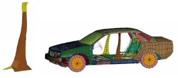
The B-pillar of a car is the structure located between the front and rear doors of the cab. It does not only house electrical wiring and connection spots for the passenger seat belts, but it provides structural support for the cab in case of a side collision or rollover of the vehicle. Vibration generated from various sources (engine, road surface, tires, exhaust, etc.) should be considered in the design of a B Pillar. These vibrations travel through transfer systems to the steering wheel, seats and other areas where it is detected by the passengers of the vehicle. Transmission routes must be studied and efforts made to keep transfer systems from amplifying vibration and to absorb it instead.
Fig. 1. Position of B Pillar in a car
tooling costs, whereas processing of complex parts in one piece is much easier. Also by using composite material for B Pillar, reduction in weight can be observed which can lead to lesser fuel consumption.
II. RELATEDWORK
1. J.W.L.H. Maas, “Development and validation of a vibration model for a complete vehicle".
This report focuses on the development and validation of a multi-body model of a complete car. The purpose of this model is to help to predict the behavior of the vehicle with respect to vibrations early in the development process of a car. The model is kept as simple as possible to be able to make adjustments easily to both the geometry and parameters of the model. The outcome of this study is a multi-body model featuring nine masses which include four tires, three vehicle body parts, an engine and a windscreen. The model is validated using measurements on a real vehicle in the modal analysis laboratory of the BMW group. From this validation, the main discrepancies can be found in the connection between engine and vehicle body as well as the damping behavior in the entire model. However, the resonance frequencies between model and real vehicle are comparable.
2. Ying Yang , Guangyao Zhao, Dongbo Ma and Xiaobin Xu, “Mode calculation and testing of a car body in
white”
The dynamic parameters of a car body in white (BIW) are important during a new car developing. Based on the finite element method, the model of a BIW is developed in which the welding points are treated specially as a new element type and the vibration modes of it are calculated. In modal testing, a fixed sine-sweeping exciter is used to conduct a single point input force for the structure, whereas the output responses are picked up at different points to identify modes. The obtained modes are coincided both with the FE results and the practical testing.
In this paper, the modal analysis of a BIW is achieved both with finite element method and experimental test. The finite element model is established with considering the special characteristics of welding points because the boundary conditions will change the modes sensitively. Comparing with the calculated modes based on FEM to those of the tested of the BIW, it is shown that the natural frequencies and vibration shapes correspond to each other. These results will provide the basis for improving and optimizing the design of a car body.
3. Wang Youmin, Yu Chun, Chen Mingxin, Zhou Ge Dou Zongying, Yang Xaoli, Du Xiaoyang, “Car B-Pillar
Skid Plate Molding Parameter Optimization.”
To obtain the best injection molding process parameters and mold design for the car B-pillar skid plate, the process parameters of injection molding CAE needs to be optimized. After determining the parts quality standards, we complete the range and analyze the results. But this method can only identify the influence trend of parameters on the test results; it can’t get the best process parameters. This paper uses the modified simplex method as optimization method. We transform the function optimization into the injection molding CAE process optimization. The injection molding process parameters are optimized. We get the best parts injection molding process parameters: the Mold
temperature is 33.24℃, the melt temperature is 213.98℃, injection pressure is 80.12MPa, parts of the program sink
mark index is 0.5221%, volume shrinkage is 1.0143% , maximum warping deformation is 1.426mm, the cavity residual stress is 4.8333MPa. Car B-pillar skid plate is injected according to the best process parameters, the obtained parts have met our quality requirements.
III.THEORIES
1. Vibration Frequencies:
The natural frequency is a function of elastic stiffness of the part and it’s mass. The following formula gives the natural frequency of a spring mass system in mathematical form [4].
•Either Increase the Elastic Stiffness of B pillar. •Reduce the Mass of Pillar Assembly.
2. Material Properties:
The existing design is entirely made with mild steel with following properties:
Mild steel
Property Value
Young’s Modulus, E 210 GPa
Poisson’s Ratio ,ν 0.29
Density, ρ 8000 kg/m3
Yield Stress, σyield 320
MPa
Ultimate Tensile Stress, σuts
480 MPa
We are proposing following materialsto be used instead of mild steel:
Property (Aluminium B390)
Value Property (Glass Fiber) Value
Young’s Modulus, E 88 GPa Young’s Modulus, E 40.3
GPa
Poisson’s Ratio ,ν 0.33 Poisson’s Ratio ,ν 0.29
Density, ρ 3000 kg/m3
Density, ρ 1900 kg/m3
Yield Stress, σyield 250
MPa
Shear modulus in XY plane, Gxy
3070 MPa
Ultimate Tensile Stress, σuts
320 MPa
Ultimate Tensile Stress, σuts 2050
MPa
A) Aluminium B390:
Aluminium alloy 390 provides better resistance to abrasion & wear, and it was originally developed for automotive engine blocks. However, alloy 390 offers the lowest ductility of aluminium alloy with elongation of less than 1 percent. Although its density is approximately same as that of pure aluminium.
Material Composition
Materials Aluminium Copper Magnesium Iron (Max)
Nickel (Max)
Zinc Manganese Silicon Titanium Other Metallics
Percentage (%)
72.7 – 79.6 4-5 0.45 – 0.65 1.3 0.10 1.50 0.50 16 –
18
0.10 0.20
B) Glass Fiber:
Also, from manufacturing feasibility point of view, glass fiber is much cost effective. As processing of glass fiber is much easier than of carbon fiber. Hence, glass fiber composites are less expensive than carbon composites in most cases.
Due to the above mentioned advantages, ease of manufacturing & cost effectiveness, we have chosen glass fiber over carbon fiber.
IV.DESIGNOFBPILLAR
Dimensions of the existing B-pillar have been measured with reference to actual vehicle and respective CAD model of a B-pillar has been prepared in CATIA V6.
Fig.3. Measurements taken with reference to existing Mahindra Bolero B Pillar
The overall wall thickness of body was 2mm side design including the lower and upper rails for inner and outer panel. Thus, full range of thickness from body side design was incorporated in this design.The new design as in above figure is intended to develop and demonstrate the use of carbon fiber composite structures to generate significant weight savings for an automobile. The first phase was a structural design study. This study proposed variable thickness panels to maximize the structural efficiency at minimum mass. The wall thickness is constrained to be at 2 mm. For the structural analysis of the B-Pillar, Finite Element Method was used since it is the most widely used computational method in the automotiveindustry.
V. FINITE ELEMNT ANALYSIS OF B PILLAR
To perform FEA on B Pillar, the prepared CAD model is imported into Hypermesh for Pre-processing, and the CAD model is meshed with following parameters:
Element Type Shell 63 (2D element)
Number of Nodes 8154
Number of Elements 30324
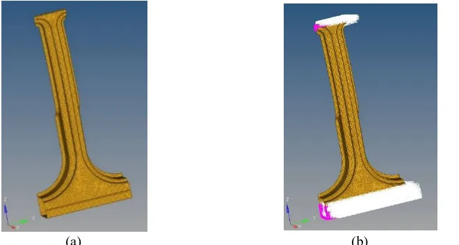
According to the existing position of B Pillar in a vehicle’s chassis, the upper and inner railings act as fixed members as they are fixed to roof and bottom chassis of the vehicle. Thus, to carry out modal analysis on B Pillar, we choose to treat the upper and lower railings as fixed supports. Hence, after applying these boundary conditions we get:
(a)
(a) (b)
Fig. 5. (a) Meshing of BIW B-pillar in Hypermesh (Shell 63 – 2D Mesh), (b) Meshed model of B Pillar with boundary conditions applied in Hypermesh.
VI.MODAL ANALYSIS OF B PILLAR
What is modal analysis?
Modal analysis is the study of the dynamic properties of structures under vibration excitation. Modal analysis uses the overall mass and stiffness of a structure to find the various periods at which it will naturally resonate. These periods of vibration are very important to note in vibration of any machine, as it is imperative that a components or nearby system’s natural frequency does not match the frequency of machine. If a structure's natural frequency matches a component's frequency, the structure may continue to resonate and experience structural damage.
Post – Processing:
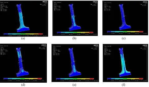
Results Of Modal Analysis On Existing Mild Steel B-Pillar:
(a) (b) (c)
(d) (e) (f)
Fig. 6. (a) 1st Mode shape and it’s respective frequency = 267.956 Hz, (b) 2nd Mode shape and it’s respective
frequency = 319.089 Hz, (c)3rd Mode shape and it’s respective frequency = 382.783 Hz, (d) 4th Mode shape and
it’s respective frequency = 407.302 Hz, (e) 5th Mode shape and it’s respective frequency = 425.436 Hz, (f) 6th Mode shape and it’s respective frequency = 447.042 Hz.
Modal Analysis Results for existing Mild Steel B-Pillar:
Mode Shape Frequency
1st Mode Shape 267.96
2nd Mode Shape 319.09
3rd Mode Shape 382.78
4th Mode Shape 407.30
5th Mode Shape 425.44
6th Mode Shape 447.04
Proposed Changes:
(a) (b)
Fig. 7. (a) Proposed Aluminium Model with the layer of Composite Reinforcement, (b) Meshed model of Aluminium B Pillar with reinforcements with boundary conditions.
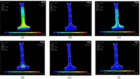
Results Of Modal Analysis Carried Out On Aluminium & Composite Reinforced B – Pillar:
(a) (b) (c)
(d) (e) (f)
VII.ANALYSIS RESULTS Comparison of Modal Analysis Results:
Modes
Frequency (Hz)
Mild Steel Aluminium reinforced with Glass Fiber
1 267.96 110.24
2 319.09 174.42
3 382.78 204.29
4 407.30 226.71
5 425.44 240.31
6 447.04 267.601
Closure:
The comparison, between modal analysis results of existing B-pillar with mild Steel and Aluminium reinforced with Glass Fiber, has been performed and it is summarized in table shown above.
The comparison shows that the frequencies of vibration of Mild Steel reinforced with Glass Fiber B-pillar in
six different modes are lower than that of B-pillar with only mild Steel.
This is due to the implementation of the Glass Fiber as the material for reinforcement.
Glass Fiber is proven to be better in damping behaviour.
Hence the comparison shows that the main objective of this research work has been satisfied.
VIII. CONCLUSION
As it can be seen from Table above, the lowest frequency for existing Mild Steel B Pillar is 267.96 Hz & highest frequency is 447.04 Hz. It can be observed that, the obtained frequency values for Aluminium B Pillar reinforced with Glass Fiber, are below the lowest occurring frequency of existing B Pillar, thus there is no chance of resonance at all. Thus this new proposed design with reinforced composite is considered to be safe. Also after implementation of this newly proposed design in vehicles, the operating frequencies of composite reinforced B-Pillar would be overtaken over at the initial phase of drive of vehicle when it has just begun to move i.e. in 1st or 2nd gear during vehicle operation. Thus, for the larger part of the drive, as vehicle would be normally operating on higher gears, the operational frequency of the vehicle would not match the natural frequency of Composite Reinforced B-Pillar, hence avoiding any resonance to occur & also protecting the passengers from any hazards due to resonance. The weight of the composite B-Pillar is reduced drastically when compared to the existing Mild Steel B-Pillar. The gross weight of the composite B-Pillar is approximated to be around 2.255 kg whereas the weight of the present B-Pillar made of steel is 6.343 kg. The weight of the composite is 64.207% less when compared to the steel B-Pillar. This shows the weight reduction when a composite material is used. Further, to continue the optimization the proposed model, we can replace Glass Fiber with carbon fiber & then compare the models for better strength and lower natural frequencies.
REFERENCES
[1] J.W.L.H. Maas, “Development and validation of a vibration model for a complete vehicle", Eindhoven University of Technology, Eindhoven - January 2008.
[3] Sameer Gupta, “Using Cae to Evaluate Structural Foam Alternatives In B-Pillar And Bumper Designs”, 3rd European LS-DYNA Users Conference, Paris - 2001.
[4] Wang Youmin, Yu Chun, Chen Mingxin, Zhou Ge Dou Zongying, Yang Xaoli, Du Xiaoyang, “Car B-Pillar Skid Plate Molding Parameter Optimization”, Journal of Theoretical & Applied Information Technology . 1/20/2013, Vol. 47 Issue 2, p586-589.
[5] Sameer Gupta, “Using CAE to evaluate a structural foam design for increasing roof strength”, 8th European LS-DYNA Users Conference, Strasbourg - May 2011.
[6] Luo Yun, Feng Guoying, Du Yongzhao, Zhou Shouhuan “The Dynamic Response Analysis of Auto Body Sheets to Node Loads”, Int. Journal of Engineering Research and Applications, Vol. 4, Issue 1( Version 1), January 2014, pp.201-205.
[7] Mr. G. R. Nikhade, “Modal Analysis of Body in White”, International Journal ofInnovative Research in Science & EngineeringVol. 2, Issue 12 pp 800-805.
[8] S. H. Jee and J. C. Yi, “The Application of the Simulation Techniques to Reduce the Noise and Vibration in Vehicle Development”, Seoul 2000 FISITA World Automotive Congress, 2000, pp. 1-7.
[9] C. Schedlinski, F. Wagner, K. Bohnert, J. Frappier, A. Irrgang, R. Lehmann and A. Müller, “Experimental Modal Analysis and Computational Model Updating of a Car Body in White”, Proc. of ISMA2004; Leuven, Belgium, 2004.
[10] A. H. Karwande and B. R. Borkar, “Finite Element Modelling and Analysis of BIW Part”, International Journal of Emerging Technology and Advanced Engineering, Vol. 3(3), 2013, pp. 202-209.
[11] R. Brincker, P. Andersen, and N. Møller: “Output-only Modal Testing of a car body subject to Engine Excitation”, Proc. Of the 18th International Modal Analysis Conference, San Antonio, Texas, 2000.
[12] J. Helsen, L. Cremers, P. Mas and P. Sas, “Global static and dynamic car body stiffness based on a single experimental modal Analysis test”, Proceedings OF ISMA, 2010.
[13] D.B. Miracle, S.L. Donaldson, “Introduction to Composites”. Journal of Composite Materials, vol.34, pp.200-215, 1995.
[14] Farley, G.L.,and Jones, R.M., “Crushing Characteristics of Continuous Fiber- Reinforced Composite Tubes,” Journal of Composite Materials, Vol.26, No.1, pp. 37-50, 1992.