information is subject to change without notice and should not be construed in any way as a commitment by Mitel or any of its affiliates or subsidiaries. Mitel and its affiliates and subsidiaries assume no responsibility for any errors or omissions in this document. Revisions of this document or new editions of it may be issued to incorporate such changes.
No part of this document can be reproduced or transmitted in any form or by any means - electronic or mechanical - for any purpose without written permission from Mitel Networks Corporation.
Trademarks
Mitel, SX-2000, SUPERCONSOLE 1000, and SUPERSET are trademarks of Mitel Networks Corporation.
Windows is a trademark of Microsoft Corporation. Cisco is a trademark of Cisco Systems, Inc.
VT100 is a trademark of Digital Equipment Corporation. Java is a trademark of Sun Microsystems Incorporated.
Other product names mentioned in this document may be trademarks of their respective companies and are hereby acknowledged.
3300 Integrated Communications Platform Technician’s Handbook
Release 7.0 51009611, Rev. A
May 2006
®,™ Trademark of Mitel Networks Corporation ©Copyright 2006, Mitel Networks Corporation
Chapter 1 : Introduction
Purpose of this Handbook ...3
Symbols Used in the Handbook ...3
Safety Instructions ...3
Start Here Guide ...4
What You Received ...4
Installation Tools and Equipment ...4
Installation Checklist ...5
About the 3300 ICP ...6
Programming Tools ...6
Installation/Maintenance Computer ...7
Launching the Programming Tools ...8
3300 ICP Documentation ...9
Mitel OnLine ...10
Contacting Mitel ...11
Chapter 2 : Installation Install Controller Components ...15
Controller Component Options ...18
Hard Drive ...19
LX, 100, 250 and 700-User Hard Drive ...19
MX Hard Drive ...19
System ID Module ...20
Other Controller Components ...20
Mounting the MXe Controller ...20
Connecting the Maintenance PC to the Controller ...22
Requirements for AMC Connection ...23
Basic Programming and Data Save ...25
Connecting the Controller to the Network ...27
Programming DHCP ...29
Install Units ...36
Universal or R2 Network Services Unit ...36
BRI Network Services Unit ...37
Analog Services Unit ...38
Embedded Analog, Configure ...39
Peripheral Cabinet ...40
SUPERSET HUB ...45
Digital Service Unit ...47
Install Telephones and Peripherals ...51
Installing Telephones, Consoles and Appliances ...51
Installing Line Interface Modules ...52
Programming Phones ...52
Registering IP Devices from the Telephone ...52
Setting Static IP Address on IP Display Set ...54
Chapter 3 : Software Procedures
Back Up a Database ... 61
Restore a Database ... 63
Upgrade/Install System Software ... 66
Software Upgrade Options ... 66
Upgrade/Install Options with Cluster or Dimension Changes ... 67
Installing the Software Installer Tool ... 69
Installing System Software on the FTP Server ... 70
Installing System Software on the Controller ... 71
Upgrading System Software ... 72
Applying a Software Patch ... 76
Installing System Software Manually ... 77
Upgrading/Installing with Maximum Elements Change ... 83
Upgrade to Rls 6.0 or later with Flexed Dimensions ... 84
Programming Overview ... 86
Install 6000 MAS Software ... 87
Install and Use IMAT ... 88
Installing IMAT on the PC ... 88
Programming an IP Address into the NSU ... 88
Using IMAT ... 90
Install the Java Plug-In ... 93
Chapter 4 : Upgrades and FRUs About this Chapter ... 97
Safety Considerations ... 98
Upgrade a 3300 ICP ... 98
Power Down the Controller ... 99
Perform a System Reset ... 99
Removing/Replacing LX/700-User Controller Cover ... 99
Removing/Replacing MX/100-User Controller Cover ... 100
Removing/Replacing CX/CXi/MXe Controller Cover ... 101
Upgrading to a 300 or 450 MHz Controller ... 102
Upgrading to a 700-User Controller ... 103
Add or Replace Controller FRUs ... 104
Dual Fiber Interface Module (FIM) ... 104
DSP Module ... 105
Framer (Dual T1/E1, T1/E1 Combo, Quad BRI) ... 110
Echo Canceller ... 112
Analog Option Board (MX Controller) ... 113
Analog Option Board (CX/CXi Controller) ... 114
Add Controller FRUs ... 116
MXe RAID Controller ... 116
Redundant Hard Drive (MXe) ... 117
Application Processor Card (CXi) ... 118
APC Hard Drive (CXi) ... 121
Configure the System for 6000 MAS ... 122
Redundant Power Supply (MXe) ... 123
Replace Controller FRUs ...125
Hard Drive Replacement Overview ...125
LX, 100, 250, 700-User Hard Drive ...126
MX Hard Drive ...127
MXe Hard Drive, Single ...128
MXe Hard Drive, Redundant ...129
MXe Hard Drive, Both Redundant Drives ...130
CX/CXi Hard Drive ...131
System ID Module ...133
System i-Button (CX/CXi and MXe) ...133
Analog Main Board (MX Controller) ...134
Analog Main Board (MXe Controller) ...136
Analog Main Board (CX/CXi Controller) ...137
RTC Processor (MXe) ...138
Cooling Fan (MXe) ...139
Power Supply Unit (MXe) ...139
Stratum 3 Clock Module ...140
Install ASU II FRUs ...141
Line Card (16 Port ONS / 4+12 Port Combo) ...141
Power Supply ...141
Install Peripheral Cabinet FRUs ...142
Powering Down the Peripheral Cabinet ...142
Powering Up the Peripheral Cabinet ...143
Replacing Circuit Cards ...143
Replacing a Power Converter ...144
Replacing the Power Distribution Unit (PDU) ...145
Replacing a Cooling Fan ...146
Replacing the Fiber Interface Module (FIM) ...147
Expanding a Peripheral Cabinet II ...147
Installing an Expanded Peripheral Cabinet ...149
Replacing a Peripheral Switch Controller Card ...150
Install Digital Service Unit FRUs ...151
Removing/Replacing the Front Panel ...151
Powering Down the DSU Unit ...151
Replacing Circuit Cards ...151
Installing a BRI Card ...152
Installing a Formatter Card (CEPT, DS1) ...154
Installing a PRI Card ...154
Installing a Peripheral Resource Card (PRC) ...156
Replacing a DSU FIM ...157
Installing a DSU FIM ...158
Installing an R2 Card ...158
Install SUPERSET HUB FRUs ...161
Installing a Fiber Interface Module ...161
Chapter 5 : Troubleshooting
About this Chapter ... 167
Troubleshooting Tools ... 168
Using the Phone Debug Option ... 170
Using the Dual Mode Phone Debug Option ... 171
IEEE 802.1X Authentication for IP Phones ... 176
Before You Contact Technical Support ... 179
General Troubleshooting Steps ... 181
View Alarms ... 182
Alarm Levels ... 182
View Alarms ... 182
Troubleshoot Software ... 183
Embedded System Management (ESM) ... 183
Installation and Upgrade ... 183
Downgrading to a Previous Software Release ... 185
Backup and Restore ... 186
Audio File Downloads ... 188
Troubleshoot Hardware ... 189
Alarms ... 189
Embedded T1/E1 (PRI, T1/D4, or MSDN/DPNSS) ... 191
Embedded BRI ... 193
Network Services Units (NSUs) ... 194
Analog Services Units (ASUs) ... 196
In-Line Power ... 197
Power Over Ethernet ... 201
Digital Service Units (DSU) ... 201
Troubleshoot Digital Trunks ... 203
Digital Trunking ... 203
Troubleshoot the Network ... 204
IP Trunking ... 204
LAN ... 204
E2T ... 206
CXi-specific Issues ... 207
PC Network Connectivity ... 209
IP Phone Registration ... 210
Troubleshoot Phones and Peripherals ... 217
Phone Connection ... 217
Phone Audio Quality ... 222
IP Phone Boot Sequence ... 225
Checking the IP Phone Progress Display ... 230
IP Console ... 231
Chapter 6 : Maintenance General Maintenance Procedures ... 235
Checking the System ... 235
Checking Controller Hardware Profile ... 235
View Logs ...237
Viewing Maintenance or Software Logs ...237
Collecting System Logs, Release 5.2 and Later ...238
Collecting System Logs, Release 5.1 ...239
Viewing Logs Remotely, TCP/IP Socket Numbers ...241
Viewing Login and Logout Audit Logs ...242
Device Connectivity ...244
Automatic CESID Update ...244
Monitoring Device Move Detection ...244
Device Move Detection Procedures ...247
Viewing Device Connectivity Logs ...247
IP Phone Analyzer ...248
Installing the IP Phone Analyzer ...248
Launching the IP Phone Analyzer ...248
Enabling Tool Analysis ...248
Disabling Tool Analysis ...249
LSMeasure Tool ...250
Appendix A : Hardware Reference System Configurations ...253
Controller Hardware Details ...253
Controller Cabinet Numbering ...259
T1/E1 Combo Card ...259
Dual T1/E1 Framer ...261
Quad BRI Framer ...261
Analog Board (MX Controller) ...262
Analog Board (CX and MXe Controllers) ...264
Controller Alarm Port Pinouts ...266
Controller Remote Alarm Behavior ...266
Network Services Units ...267
Universal/R2 NSU ...267
BRI NSU ...271
Analog Services Unit ...273
5485 IP Paging Unit ...278
Peripheral Cabinet ...279
Digital Service Unit ...289
IP Phones ...293
Powering Features ...293
Appendix B : Installation Planner CXi/MXe Requirements for IP Networking ...297
Controller Configuration Settings (RTC) ...300
DHCP Configuration Settings ...301
Programming E2T via Debug Cable or Secure Telnet ...306
Configuring External DHCP Settings for E2T ...307
Configuring a Windows 2000 DHCP Server (prior to Release 7.0) ...308
Configuring a Windows 2000 or Windows 2003 DHCP Server (Rls 7.0 and later) ...310
IP Phone Settings ... 312
Telephone Programming Guide ... 313
Appendix C : Typical Network Configurations Network Configuration Examples ... 317
Configuration 1: One DHCP Server per VLAN ... 318
Configuration 2: One DHCP Server for Two VLANs ... 320
Configuration 3: Router on a Stick ... 321
Cisco Discovery Protocol (CDP) ... 322
CXi/MXe Configuration Procedures ... 323
Firewall/Port Forwarding ... 323
PPTP Remote Access ... 323
WAN Settings (Internet Gateway) ... 323
Configuration 1: CXi Typical Voice-Only Network ... 324
Configuration 3: CXi Typical Voice and Data Network ... 326
Configuration 4: MXe Typical Voice and Data Network ... 327
Windows 2000 FTP Server ... 328
Appendix D : Status LEDs Controller LEDs ... 333
Power Status, Front Panel ... 335
Hard Drive Activity, Rear Panel, ... 335
RAID Controller ... 336
FIM ... 338
LAN Ethernet Ports ... 338
CIM ... 340
Controller Alarm ... 340
Power Supply Unit LEDs ... 342
Dual T1/E1 Framer Module ... 342
T1/E1 Combo Card ... 343
Quad BRI Framer Module ... 345
Network Services Unit LEDs ... 346
Universal/R2 NSU ... 346
BRI NSU ... 350
Analog Services Unit LEDs ... 351
ASU II Card LEDs ... 353
IP Device LEDs ... 354
Peripheral Cabinet LEDs ... 355
Digital Services Unit LEDs ... 356
In-Line Power Unit LEDs ... 361
Appendix E : FRU Part Numbers Hardware Part Numbers ... 365
Software Part Numbers ... 371
Appendix F : System Capacity and Parameters System Parameters ... 375
Encryption Support ...376
Set Compression ...376
Mitel IP Phone Power Consumption ...377
Capacity ...378
Hardware Capacity ...378
System Capacity ...379
Purpose of this Handbook
This handbook provides instructions to install, upgrade, maintain and troubleshoot the Mitel® 3300 Integrated Communications Platform (ICP). This handbook is written for certified 3300 ICP technicians. For information on programming tasks, please refer to the System Administration Tool Help system.
Symbols Used in the Handbook
Safety Instructions
A printable version of the Safety Instructions is available on the Mitel Customer Documentation web site.
Tip: Provides additional information you should know about a topic.
Time: Indicates the time it takes to complete a procedure.
CAUTION: Indicates a potentially hazardous situation that could result in damage to the equipment.
WARNING: INDICATES A HAZARDOUS SITUATION THAT COULD RESULT IN INJURY OR DEATH.
CAUTION: Failure to follow all instructions may result in improper equipment operation and/or risk of electrical shock. Refer to “3300 Safety Instructions” for complete safety information.
CAUTION: To prevent ESD damage to the equipment: (1) Ensure that the system is grounded before you install a card. (2) Whenever you handle cards, wear an anti-static strap (attached to the cabinet). (3) When removing cards from the cabinet, immediately place them in an anti-static bag.
Start Here Guide
What You Received
Options sheet with password from Mitel OnLine (see page 11) 3300 ICP Controller
Hard drive
System ID module or System i-Button Software CD-ROM
NSU, ASU (optional)
Set of feet, rack ears, and screws for each unit
Review your purchase order for other, optional, components.
Installation Tools and Equipment
Installation Planner (Appendix B on page 295)
Typical Network Configurations (Appendix C on page 317) Computer for programming the 3300 ICP
CAT 5 or better Cable with RJ-45 connector
IP addresses for the controller, E2T, and IP telephones List of purchased options and password
IMAT (not required if you have Embedded PRI) Phillips screwdrivers
Installation Checklist
Obtain your options and password from Mitel OnLine Complete the Installation Planner Appendix (see page 295) Install controller hardware (see page 15)
Connect maintenance PC to Controller (see page 22) Power up the Controller (see page 22)
Launch the System Administration Tool (see page 8) Program the License and Options Selection (see page 25) Perform a DBMS Save (see page 25)
Set the Date and Time (see page 26)
Program the Controller modules (see page 26)
Establish an Ethernet connection to the Controller (see page 27) Set the Controller RTC IP address (see page 28)
Program the DHCP server (see page 29) Configure the Layer 2 switch (see page 35)
Install NSU, ASU, Peripheral Cabinet, DSU, SUPERSET™ Hub (page 36)
Program Units and Modules (follows each installation procedure) Install Telephones (see page 51)
Register IP Devices (see page 52) Program Telephones (see page 54)
Install a DNIC Music on Hold /Paging Unit (see page 57) Program Trunks (see System Administration Tool OnLine Help) Program Automatic Route Selection (see OnLine Help)
Program Voice Mail (see OnLine Help) Program Paging (see OnLine Help) Program Music on Hold (see OnLine Help)
Program Automatic Call Distribution (see OnLine Help) Program Hotel/Motel (see OnLine Help)
About the 3300 ICP
The 3300 ICP is a Voice over IP solution that delivers voice capabilities and features to the enterprise. There are several system configurations: the 100-user system; the MX with embedded analog, that can support 200 users; the CX and the CXi with embedded analog and embedded Layer2 switch for sites with an 8-64 line size; the MXe base with embedded analog that can support 200 users before expansion; and the LX that can support 700 users (with 256 MB RTC memory) or 1400 users (with 512 MB RTC memory from Release 6.0).
Programming Tools
The system includes a number of programming tools:
• Embedded System Management (ESM) consists of:
- System Administration Tool that provides a Web-based interface
that trained technicians use to program the system.
- Group Administration Tool that provides a Web-based interface
to enable administrators to make changes to user information.
- Desktop Tool that provides a Web-based interface to enable
display IP telephone users to program feature keys on their phone.
• Configuration Wizard, introduced with Release 7.0, allows you to
customize initial system programming. After you specify the system setup, you can save the details for future use or apply the changes to the 3300 ICP.
• ISDN Maintenance and Administration Tool (IMAT) provides the
programming interface for PRI and R2 protocols delivered via an NSU or DSU. Embedded PRI via the Dual T1/E1 Framer is programmed though the System Administration Tool.
• ICP Software Installer Tool expedites the distribution of 3300 ICP
software by eliminating a number of interactive steps (see page 69). The tool restores saved databases and, from Release 7.0 UR1, enables databases from legacy SX-2000® LIGHT, SX-2000 MicroLIGHT, 3200 ICP, and 3800 WAG systems to migrate to the 3300 ICP. The Software Installer Tool replaces the Configuration Tool.
• Configuration Tool restores saved databases and enables legacy
• IP Phone Analyzer collects performance information about the IP devices connected to the 3300 ICP. You can use one PC to monitor the debug and status information of IP phones (see page 248).
• OPS Manager enables you to control the maintenance and operation
of a network of elements. With OPS Manager, you can, for example, manage a network telephone directory, schedule move, add, change, and delete user operations, and integrate the network telephone directory with a directory service database.
Application Management Center (AMC)
The online licensing process, managed by the Mitel Application
Management Centre (AMC) allows Solution Providers who have accounts on the AMC to manage software licenses online. Each company is able to supply customers instantly if new licenses are required. Refer to
“Requirements for AMC Connection” on page 23 for Software Installer Tool and 3300 ICP system networking requirements.
Installation/Maintenance Computer
You need a Windows-based computer to program, maintain and troubleshoot the 3300 ICP, and to install/upgrade 3300 ICP software.
Computer Recommendations
• Windows® NT 4.0, Windows 2000, or Windows XP
Computer Requirements
• Windows 98, Windows NT 4.0, Windows 2000, or Windows XP
• Network interface card (NIC)
• 525 MB free disk space (minimum)
• Internet Explorer 6.0 with the latest Service Pack and 128-bit encryption
• VT100™ emulator program
• FTP server (can be installed with Microsoft® IIS or PWS, for example)
Launching the Programming Tools
Embedded System Management Tools
To log into one of the ESM tools:
1. Launch a browser and go to the URL of the 3300 Controller -
https://<hostname>/main.htm (<hostname> is the name or IP address assigned to the Controller if no DNS is available). Refer to “Setting the Controller RTC IP address (for Release 6.0 and later)” on page 27 or “Setting the Controller RTC IP address (prior to Release 6.0)” on page 28.
2. The first time you connect, you must install the Mitel Root CA security certificate (see “Secure Sockets Layer (SSL) and Security Certificate” on page 236).
3. Log into the 3300 ICP ESM using the default username (system) and password (password).
4. Click the desired Tool (Desktop, Group Administration, or System Administration).
5. You will be prompted to install some XML Components when you log into the System Administration Tool for the first time. At the following prompt, "Do you wish to install or upgrade the required XML
components?", click "Install Now". The install takes less than 30 seconds and you do not need to restart your computer.
ISDN Maintenance and Administration Tool
To launch IMAT on the Installation/Maintenance PC:
• On the Start menu, point to Programs, and click IMAT.
Tip: To prevent unauthorized use, change the username and password the first time you log in.
Tip: Your PC must have the same subnet address as the RTC IP (for example, 192.168.1.x) to launch ESM.
Software Installer Tool
To launch the Software Installer Tool:
• On the Start menu, point to Programs, and click Mitel 3300ICP
Software Installer Tool.
IP Phone Analyzer
To launch the IP Phone Analyzer:
• On the Start menu, point to Programs, and click Mitel IP Phone
Analyzer (see page 248 for details).
3300 ICP Documentation
The 3300 ICP documentation set includes the following components:
• Printed documents (also available on Mitel OnLine)
- General Information Guide - Technician’s Handbook - Safety Instructions • Documents on Mitel OnLine
- Hardware Technical Reference Manual - System Administration Tool Help
- Voice Clustering (Portable Directory Number) - Resiliency
- IP Phone Analyzer Online Help - Software Installer Tool Help
- IP-DECT Wireless Solution Documentation - CITELlink Gateway Documentation
- Symbol NetVision MiNET Phone Installation and Programming Instructions
- SpectraLink Documentation - Engineering Guidelines
• Online Help
- System Administration Tool Online Help - Group Administration Tool Embedded Help - Desktop Tool Embedded Help
- IMAT Online Help
- IP Phone Analyzer Online Help - Software Installer Tool Online Help - OPS Manager Online Help
• Knowledge Base Articles on Mitel OnLine
- Technical Bulletin - How-To Guide
- Troubleshooting Guide - Known Product Issue - Release Notes - Program Information.
Mitel OnLine
You can access Mitel OnLine from the www.mitel.com Web site.
Access Product and Technical Documentation
1. Log into Mitel OnLine.
2. Click Technical Support.
3. Click Product Documentation for Technical Documents, User Guides, and Installation Guides.
-OR-Click Knowledge Base for TBs and RNs.
Tip: In the software application (System Administration Tool, IMAT, etc.), click the Help link or button to access the tool’s Online Help.
Tip: You must be a registered user to access Mitel OnLine.
Create Telephone User Guides with ManualMaker
1. Log into Mitel OnLine.
2. Click Technical Support and then click Product Documentation.
3. Click ManualMaker.
4. Click the Help button for instructions on creating User Guides with ManualMaker.
Access Your Mitel Options Password
You must obtain your Mitel Options Password through Mitel OnLine (www.mitel.com). This password is required during a software upgrade or installation procedure, so you MUST keep a proper record of it. A new password is issued to you if you are purchasing new options. Before attempting to upgrade software, to confirm a current password or to purchase new options and receive a new password, call Mitel Customer Service during normal business hours.
Contacting Mitel
Sending Feedback
If you have suggestions on how to improve this documentation, please contact us at [email protected].
Order Desk
You can reach the Order Desk at 1-800-796-4835.
Repair Department
You must get a Return of Merchandise Authorization (RMA) form from the Repairs Department before sending equipment back to Mitel.
You can reach the Repairs Department at 1-888-222-6483.
Technical Support
Please contact Mitel Technical Support if you require technical assistance.
If you cannot resolve the problem by using the Troubleshooting chapter (page 165), please collect the required information listed in the applicable section(s) of the Troubleshooting chapter before calling Mitel Technical Support.
Install Controller Components
This chapter contains instructions on how to install a 3300 ICP. For information on upgrading and replacing components, see page 104.
In the following illustrations, the components listed in bold text are installed in the factory (Release 7.0 and later). If you receive a
CX/CXi/MXe and those identified components are not installed, refer to Chapter 4 on page 95 for installation instructions.
Figure 1: Slot Locations for the LX, 250, and 700-User Controllers
Figure 2: Slot Locations for the MX Controller
Tip: In the following illustrations, T1/E1 refers to Dual T1/E1 or T1/E1 Combo, with exception of the CX/CXi controllers which support only the Combo.
Power Supply Slot 8 DSP Slot 7 DSP Slot 6
Echo Canceller or DSP
Slot 5 Echo Canceller
SysID
Slot 1
FIM, T1/E1, or BRI
Slot 2
FIM, T1/E1, or BRI
Slot 3
FIM, DSP, T1/E1, or BRI
Slot 4
FIM, DSP
Power Supply
Analog Main Board
Analog Option Board
(optional, installed on AMB)
Hard Drive
Clock Module SysID
Slot 1
FIM, T1/E1, or BRI
Slot 2
FIM, DSP, T1/E1, BRI
Slot 3
DSP, T1/E1, or BRI
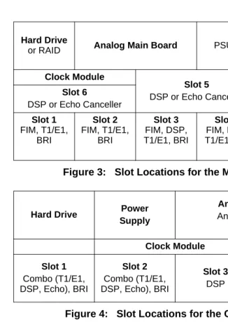
Figure 3: Slot Locations for the MXe Controller
Figure 4: Slot Locations for the CXi Controller (with an Ethernet L2 Switch)
Figure 5: Slot Locations for the CX Controller (without an Ethernet L2 Switch)
Hard Drive
or RAID Analog Main Board PSU 2 PSU 1
Clock Module
Slot 5
DSP or Echo Canceller i-Button
Slot 6
DSP or Echo Canceller
Slot 1 FIM, T1/E1, BRI Slot 2 FIM, T1/E1, BRI Slot 3 FIM, DSP, T1/E1, BRI Slot 4 FIM, DSP, T1/E1, BRI
Hard Drive Power Supply
Analog Main Board
Analog Option Board
(optional)
Clock Module i-Button
Slot 1
Combo (T1/E1, DSP, Echo), BRI
Slot 2
Combo (T1/E1, DSP, Echo), BRI
Slot 3
DSP
16 Port Ethernet L2 Switch
Hard Drive Power Supply
Analog Main Board
Analog Option Board
(both optional)
Clock Module i-Button
Slot 1
Combo (T1/E1, DSP, Echo), BRI
Slot 2
Combo (T1/E1, DSP, Echo), BRI
Slot 3
Figure 6: Slot Locations for 100-User Controller
Read the Safety Instructions before performing the procedures in this chapter (see “Safety Instructions” on page 3).
Connect the installation/maintenance PC to the Controller (page 22) Power up the Controller (see page 22)
Launch the System Administration Tool (see page 8) Complete basic programming and Data Save (see page 25) Establish an Ethernet connection to the Controller (see page 27) Set the Controller RTC IP address (see page 28)
Program the DHCP server (see page 29) Configure the Layer 2 switch (see page 35) Install the Units (see page 36)
Install the Telephones and peripherals (see page 51)
Power Supply
SysID
Slot 1
FIM, T1/E1, or BRI
Slot 2
FIM, T1/E1, or BRI
Slot 3
DSP or BRI
Slot 4 DSP
CAUTION: To prevent ESD damage to the equipment: (1) Ensure that the system is grounded before you install a card. (2) Whenever you handle cards, wear an anti-static strap (always attach the wrist strap from the cabinet).
Tip: Before installing a 3300 ICP, always read the RN for the software you are installing (see “3300 ICP Documentation” on page 9).
CAUTION: All installation, field replacement, and servicing procedures must be carried out by service personnel who have successfully completed the Mitel Installation and main-tenance training course.
Controller Component Options
Table 1: Controller Component and Upgrade Options
Processor speed 3001 450 266
Components 100 250 700 MX LX MXe5 CX4
CIM √ √ √ √ √ √ —
FIM (page 104) √ √ √ √ √ √ —
DSP (page 105) √ √2 √2 √ √ √ √
T1/E1 (page 110) √ √ √ √ √ √ —
BRI (page 110) √ √ √ √ √ √ √
T1/E1 Combo (page 111)
√ √ √ √ √ √ √
AMB (page 136) — — — — — √ √
AOB (page 114) — — — — — — √
AMB (page 134) — — — √ — — —
AOB (page 113) — — — √ — — —
Redundant Power Supply (page 123)
— — — — — √ —
RAID controller (page 116)
— — — — — √ —
E2T (page 123) — — — — — √ —
Upgrading to a 300 or 450 MHz Controller (page 102)
— √ √ — — — —
Upgrading to a 1400-User System
— — — — √3 √6 —
Note: 1. Requires 3300 ICP software version 3.2 or higher.
2. 64 compression channels requires a minimum 300 MHz controller.
3. Requires a controller with 512 MB of memory on the RTC (Rls 6.0 or later).
4. The CX only supports Release 6.0 or later software.
5. Release 7.0 and later software.
6. Requires the installation of a second processor, the E2T.
Hard Drive
LX, 100, 250 and 700-User Hard Drive
To install a new hard drive in a new LX/100/250/700-user controller:
1. Remove the controller from its packaging.
2. Remove the hard drive and attached backing plate from its packaging.
3. Locate the hard drive ribbon cable and power cable in the controller hard drive enclosure.
4. Cut and discard the tie wrap securing the cables to the controller stand-off post.
5. Connect the power and ribbon cables in the hard drive enclosure to the corresponding connectors on the hard drive.
6. Insert the hard drive.
7. Secure the plate to the controller using the 6 border screws provided with the hard drive.
MX Hard Drive
To install a new hard drive in a new MX controller:
1. Remove the controller and hard drive from their packaging.
2. Remove the top cover of the controller (see page 100).
3. Discard the backing plate that is shipped with the hard drive.
4. Locate the hard drive ribbon cable and power cable in the controller hard drive enclosure.
CAUTION: If you move a programmed hard drive from one controller type to another (for example, an MX system to an LX or CX system), you MUST manually install the software (see page 77) and restore the database. A new hard drive pur-chased from Mitel is configured for installation in any system.
5. Connect the power and ribbon cables to the corresponding connectors on the hard drive.
6. Insert the hard drive.
7. Secure the hard drive to the controller using the screws provided.
System ID Module
To install a SysID module in a LX/MX/100/250/700-user controller:
1. Remove the System ID module from its packaging.
2. Remove the protective cover from the System ID module’s connector.
3. Remove the controller cover (see page 99 or page 100).
4. Install the module connector in its mate on the controller.
- 100-user controller: behind slot 2 - MX controller: behind slot 4
- LX and 250/700-User controller: between slots 1 and 8. 5. Secure the System ID module using the screw provided.
Other Controller Components
Refer to “Upgrades and FRUs” on page 95 for instructions to install additional controller components.
Mounting the MXe Controller
To rack-mount the MXe:
1. Attach the mounting brackets to the MXe using the flat head screws provided.
2. Loosely install one frame mounting screw on each side of the frame:
- in the bottom hole position of the space that the MXe will occupy.
Tip: The CX/CXi/MXe controllers are shipped with the i-Button installed. If you receive a CX/CXi/MXe and the i-Button is not installed, refer to page 133 for installation instructions.
- loosely enough that the frame mounting bracket can be dropped into position, resting on the screw thread (see Figure 7).
3. Position the MXe on the frame, resting the MXe mounting brackets on the frame mounting screw thread.
- The MXe will rest on those screws while the remaining screws are installed.
4. Install two more screws on each side of the frame, in the 3rd and 6th hole positions.
5. Tighten all six of the mounting screws.
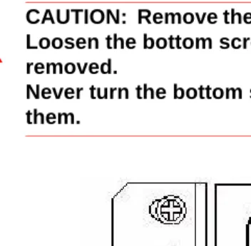
CAUTION: Remove the MXe from the rack in reverse order. Loosen the bottom screws before the other screws are removed.
Never turn the bottom screws while the rack is resting on them.
Connecting the Maintenance PC to the
Controller
1. Connect an RS-232 straight DTE male to female serial cable between the controller’s Maintenance port and the PC’s serial port (cable not provided).
2. Program the PC’s serial port (from the communication program) with the following settings:
- Baud Rate: 9600 - Data Bits: 8 - Parity: None - Stop Bits: 1
- Flow Control: None
3. Connect a straight-through Ethernet cable (RJ-45) from the controller leftmost Ethernet port (port 17 on the CXi; port 1 on the MXe) and the PC’s network interface card (NIC).
4. Program the PC’s NIC with the following settings:
- IP Address: 192.168.1.n (where n is a value between 30 and 254) - Subnet Mask: 255.255.255.0
Powering Up the Controller
1. Connect the female end of the power cable to the controller, and secure it with the latch (if provided).
2. Connect the other end of the power cable to a protected outlet. If necessary turn on power switch. The controller turns on.
Verify the Connections
Perform the steps below to verify the connections between the Maintenance PC and the controller.
1. To verify the serial connection, in the VT100 emulator, press ENTER. - If the serial connection is installed and programmed properly, a
right-pointing arrow (→) is displayed when you press ENTER. 2. To verify the Ethernet connection, from the PC, PING the controller’s
RTC IP address (default is 192.168.1.2).
- If the connection is installed and programmed correctly, the controller replies to the PING.
Requirements for AMC Connection
Connecting to the Application Management Center (AMC) Server requires specific settings for the Software Installer Tool and the 3300 System Administration Tool.
Software Installer (SI) Tool Requirements
The PC that is running the SI Tool has the following network requirements:
1. DNS Name Resolution: Because the SI win32sync client performs a
name lookup on “register.mitel-amc.com”, the SI host PC needs to be properly configured for DNS name resolution.
2. TCP/IP Source Port on the SI Host: A Windows operating system will
use an arbitrary high port for the TCP connection to the AMC. If the SI PC is behind a firewall, the firewall must allow connections from high ports (greater than 1024).
3. TCP/IP Destination Port on the AMC: The SI win32sync client will
attempt to establish a connection to register.mitel-amc.com TCP port 22. After 5 seconds, if the connection is not established, the client will try port 8222. If there is still no success, the third attempt is with port 80 using the HTTP/1.1 protocol CONNECT method.
If the SI PC is behind a firewall, the firewall must allow connection to at least one of port 22, port 8222, or port 8.
4. SI Host PC behind an HTTP Proxy Server: If the HTTP/1.1
CONNECT method is used and the SI PC is configured to use an HTTP proxy server, then the CONNECT request will be through the proxy server. This is the same method used by web browsers to establish HTTPS connections through proxy servers. If the SI host PC can reach https://www.mitel-amc.com from a web browser, then it should also be able to establish a win32sync connection by using the HTTP/1.1 CONNECT method. If there is a problem reaching
https://www.mitel-amc.com from a browser on the SI host PC, then the firewall and/or proxy server on the customer premise may need to be reconfigured to allow HTTP/1.1 CONNECT requests.
3300 ICP System Requirements
1. DNS Name Resolution: Because the MiSync client performs a name
2. TCP/IP Source Port on the ICP: The MiSync client will connect to TCP port 443 (https) on the AMC. If the ICP is behind a firewall, the firewall must allow TCP connections from the ICP to TCP port 443 on the AMC.
3. ICP behind an HTTP Proxy Server: The MiSync client uses HTTPS
to communicate with the AMC. The HTTP/1.1 CONNECT method is the standard used by proxy servers to proxy HTTPS. There should be no extra configuration work required. See Step 4, “SI Host PC behind an HTTP Proxy Server“ on page 23.
4. CX/CXi/MXe-Specific WAN Considerations: Program the Internet
Basic Programming and Data Save
Programming the License and Option Selection Form
To select licenses and options prior to software release 6.0:
1. Log into the System Administration Tool (see page 8).
2. Select the License and Option Selection form.
3. Click Change and fill in the fields as required (see your Mitel Options sheet). For more information, click Help.
4. Enter the Mitel Options Password and click Save.
5. Reboot the controller (see page 99).
To manually select licenses and options for release 6.0 and later:
1. Access the License and Option Selection form.
2. Click Change and leave the Application Record ID field blank.
3. Enter the number of licenses in the appropriate fields.
4. Select the appropriate Country variant and Configuration Options.
5. Enter your Password.
6. Click Save to commit your changes to the database.
7. Reboot the controller (see page 99).
Tip: Installations and upgrades require a new purchased-options password from the Mitel Application Management Center (AMC). If you use the old password, an error message is displayed.
Tip: Before you make any changes to Configuration Options, after entering the Mitel Options Password and programming the database, ensure that you have a system backup.
Tip: When you Change and Save in the License and Option Selection form (prior to Release 7.0), an error message that references “sysid # 65535“ means that the SysID or i-Button is not installed or not seated correctly.
Tip: Enable Networking Option and Mitai/Tapi Computer Integration.
To automatically select licenses and options for release 6.0 and later:
1. Complete the SystemIP Configuration form to enable the Primary and Secondary DNS Servers to establish a connection with the Application Management Center (AMC) Server (see "Requirements for AMC Connection" on page 23).
2. Access the License and Option Selection form.
3. Click Change and enter your Application Record ID.
4. Click Retrieve Licenses to query the Application Management Center (AMC) and retrieve your Purchased Options and Password.
5. Select the appropriate Country variant and Configuration Options.
6. Click Save to commit your changes to the database and to the AMC.
7. Reboot the controller (see page 99).
Setting the Date and Time and Saving the Settings
To set the system date and time:
1. Log into the System Administration Tool (see page 8).
2. In the All forms (alphabetical) list, click Maintenance Commands.
3. Enter writedatetime<year> <month> <day> <day of the week> <hours> <mins> <seconds> to set the date and time. For example,
writedatetime 2004 4 3 2 12 31 51 (2004 April 3rd Tuesday 12:31:51).
4. Perform a DBMS save using the dbms save maintenance command.
5. Enter the dbms stat command to verify the DBMS save.The system response is DBMS info: DBMS_INITIALIZED is on.
Programming the Controller Modules
1. Access the Controller Module Configuration form.
2. Highlight the module (slots 1 to 4) and click Change.
Tip: The PC that is running the Software Installer Tool has networking requirements that must be met to establish a connection with the AMC. Refer to "Installing the Software Installer Tool" on page 69 for details.
3. Select the module in the drop-down list. Choose Dual FIM, Dual Framer, Quad BRI Framer, or T1/E1 Combo.
4. If you have installed Framer or Combo modules, refer to “Program Embedded PRI/Q.SIG Trunks”, “Program T1/D4 Trunks”, or “Program Embedded BRI Trunks” in the Online Help for information.
5. Power down the controller (see page 99).
Connecting the Controller to the Network
This section assumes that the network is already set up, and that there is a serial connection between the Maintenance PC and the controller.
• Setting the Controller RTC IP address (prior to Release 6.0) (page 28).
• Programming DHCP (page 29)
• Verifying the Operation of the Controller (page 34).
• Configuring the Layer 2 Switch (page 35).
Setting the Controller RTC IP address (for Release 6.0 and later)
1. Launch a browser and go to the URL of the 3300 Controller (default RTC IP address is 192.168.1.2, default gateway 192.168.1.1).
2. The first time you connect, you must install the Mitel Root CA security certificate (see “Secure Sockets Layer (SSL) and Security Certificate” on page 236).
3. Log into the 3300 ICP ESM using the default username (system) and password (password).
4. Complete the IP Networking Configuration form to change the IP addresses.
Tip: See Table 58, “T1 and E1 Connector Pin Allocation,” on page 270 for Embedded T1/E1 pinout information.
Setting the Controller RTC IP address (prior to Release 6.0)
1. Start the communication program on the Maintenance PC.
2. Power up the controller (see page 22).
3. Press the Reset button on the controller (use a small non-metallic pointed object).
4. The communication program will instruct you to Press <SPACE><SPACE><SPACE> to stop auto-boot AFTER
countdown starts (Release 5.2 and later) or Press any key to stop
auto-boot (prior to Release 5.2).
5. When [VxWorks Boot]: is displayed, type c and press ENTER.
6. For each VxWorks setting shown in bold inTable 76 on page 300, enter a value, and then press ENTER. For all other settings, press ENTER to accept the default:
- inet on ethernet (e), IP address and subnet mask (hex) for controller RTC (Get it from your IT administrator.)
- gateway inet (g), IP address of the default gateway for the 3300 (must be outside the DHCP range)
- user (u), ftp
- ftp password (ftp)), ftp.
7. At [VXWorks Boot], type @, or press the Reset button on the controller.
Tip: The Maintenance PC must be on the same subnet as the controller.
Tip: If DHCP (flags=0x40) is being used on the E2T, leave the inet on ethernet field blank.
CAUTION: Do not use leading zeroes in the IP addresses. For example, enter 192.168.1.2; not 192.168.001.002.
Programming DHCP
Programming the Controller DHCP Server Settings (prior to Rls 7.0)
For additional information on programming DHCP settings for the 3300 ICP, refer to the System Administration Tool Online Help.
To use an external DHCP Server, do not enable the internal DHCP server and refer to “Configuring External DHCP Settings for E2T” on page 307 for instructions.
1. On the Maintenance PC, access the System Administration Tool (see "Launching the Programming Tools" on page 8).
2. In the All forms (alphabetical) list, click DHCP Subnet form, enter the subnet name, IP address and bit mask.
3. In the DHCP Static IP form, enter a static IP address for the E2T using the information on page 301 (skip this step for the MX and 100-user controllers). Assign IP addresses to specific devices by using the MAC address of the device. Assign a static IP Address to any IP Console in a cluster.
4. In the DHCP IP Address Range form, program the scope using the information on page 301.
5. In the DHCP Options form, program the options listed in Table 78 on page 301 for the scope you just programmed. Always create the following options:
- 3 Router, IP address
- 66 TFTP Server, IP address format
- 67 Boot file, string value (always /sysro/E2T8260) - 128 TFTP, IP address format (typically the controller) - 129 RTC, IP address format (typically the controller) - 130 MITEL IP PHONE, string value
In a single DHCP configuration, create the following options:
- 132 VLAN ID (optional)
Tip: You may need to change the IP address of your PC to match your customers network.
- 133 Priority, integer value of 1-6 (Optional. Required if a voice VLAN is in use. For external server use Hex LONG; for internal server use decimal value of 1-6)
- 134 Diffserv Code Point, integer value
If there are 5230 IP Appliances, create the following options:
- 6 DNS Server, IP address format
- 44 NetBIOS Name Server, IP address format
6. In the DHCP Options form, for a cluster environment, program IP Console (if any) with a static IP Address. Then, do the following:
Program Options 128 and 129 with: - Format: IP Address
- Value: IP Address of the controller that controls the device - Scope: Static: <device name><subnet>.
If different VLAN tagging and priority information is needed for the IP Console, repeat step 6 for Options 132 and 133.
If a different router is need for any IP Consoles, repeat step 6 for Option 3 and set the Value to the IP address of the router.
7. In the DHCP Lease Viewer form, ensure that there is no DHCP IP Address Lease for the IP Console MAC Addresses. If there is, delete it and then power off and power on the device.
8. In the DHCP Server form, enable the internal DHCP server.
To use an alternative DHCP server (see page 307 and page 308):
1. In the DHCP Server form, disable the internal DHCP server.
2. Program your DHCP server with the following options:
- 128 TFTP IP address format - 129 RTC IP address format
Programming the Controller DHCP Server Settings (for Release 7.0 and later)
For additional information on programming DHCP settings for the 3300 ICP, refer to the System Administration Tool Online Help.
To use an external DHCP Server, do not enable the internal DHCP server and refer to “Configuring External DHCP Settings for E2T” on page 307 for instructions.
1. On the Maintenance PC, access the System Administration Tool (see "Launching the Programming Tools" on page 8).
2. In the All forms (alphabetical) list, click DHCP Subnet form, enter the subnet name, IP address and bit mask.
3. In the DHCP Static IP form, enter a static IP address for the E2T using the information on page 301 (skip this step for the MX and 100-user controllers). Assign IP addresses to specific devices by using the MAC address of the device. Assign a static IP Address to any IP Console in a cluster.
4. In the DHCP IP Address Range form, program the scope using the information on page 301.
Note: DHCP options 128-133 used to configure Mitel IP endpoints have been reclassified as public options by the Internet Engineering Task Force (see RFC 2133 and RFC 3925). To comply with the change, Mitel recommends using either option 43 or 125, depending on the server's ability to support them and on administrator preference. (The embedded server supports both options with 125 as the factory-programmed default.) The old options can still be used to provide backward compatibility with IP sets that have yet to be upgraded with firmware that supports the new options. After the upgrade, the old options may be removed to prevent future conflicts with standard use or other vendors' use of these options.
Note: Ensure that all LLDP-compliant telephones are upgraded to firmware version 2.0.0.18 or later before you use LLDP on your network for VLAN Discovery.
Note: LLDP-MED non-compliant telephones cannot use LLDP for VLAN discovery. They must use DHCP VLAN discovery. Non-compliant sets are: 5001, 5005, 5010, 5020 IP Phones, 5140 IP Appliance, 5201, 5205, 5207, 5215 (single mode), 5220 (single mode), 5230 IP Phones, 5240 IP Appliance, 5485 IP Pager, and 5550 IP Console keypad.
5. In the DHCP Options form, program the options listed in Table 78 on page 301 for the scope you just programmed. Always create the following options:
- 3 Router, IP address
- 125 Vendor-Identifying Vendor-Specific Information or Option 43 Vendor Specific Information. Option 125 is the preferred option. - 66 TFTP Server, IP address format
- 67 Boot file, string value (always /sysro/E2T8260)
If there are 5230 IP Appliances, create the following options:
- 6 DNS Server, IP address format
- 44 NetBIOS Name Server, IP address format
6. In the DHCP Options form, for a cluster environment, program IP Console (if any) with a static IP Address. Then, do the following:
Program Option 125 (preferred) or Option 43 with:
- Format: ASCII String
- Value: IP Address of the controller that controls the device and different VLAN tagging and priority information if needed for the console
- Scope: Static: <device name><subnet>.
Assign the address Option 125 (or 43) as above, specifying different VLAN tagging and priority information if needed for the console.
Tip: The following IP addresses are reserved to provide backward compatability for legacy AMBs and ASUs:
192.168.10.1 to 192.168.10.15 through 192.168.13.1 to 192.168.13.15 The ASU II and legacy AMBs and ASUs with upgraded firmware use the following reserved addresses:
169.254.10.0 to 169.254.10.15 through 169.254.19.0 to 169.254.19.15
If a different router is need for any IP Consoles, repeat step 6 for Option 3 and set the Value to the IP address of the router.
7. In the DHCP Lease Viewer form, ensure that there is no DHCP IP Address Lease for the IP Console MAC Addresses. If there is, delete it and then power off and power on the device.
8. In the DHCP Server form, enable the internal DHCP server.
To use an alternative DHCP server (see page 307 and page 308):
1. In the DHCP Server form, disable the internal DHCP server.
2. Program your DHCP server with options 128-133.
3. Upgrade the IP Phones/ firmware to 2.0.0.18 or later.
4. Program your DHCP server with the following options:
- 43 Vendor Specific Information, string value OR
- 125 Vendor-Identifying Vendor-Specific Information, string value. 5. Delete options 128-133.
Program DHCP for VLAN (prior to Release 7.0):
Follow this procedure if using two DHCP servers: central server (external) on a default VLAN and other (3300 DHCP Server) on the voice VLAN.
Note: IP sets require a firmware upgrade to support the new DHCP options introduced in Release 7.0; otherwise, the sets will fail to boot. Such failures can occur, for example, in a resilient cluster of mixed software releases or when sets with old firmware are added to a controller after it was upgraded to Release 7.0. For the sets to boot, DHCP options 128-133 must be present in the DHCP server. After the sets have booted, options 128-133 may be removed to avoid future conflicts with standard use or other vendors’ use of these options
Note: Ensure that all LLDP-compliant telephones are upgraded to firmware version 2.0.0.18 or later before you use LLDP on your network for VLAN Discovery.
1. Set up the central DHCP Server with the following options: - 130 MITEL IP PHONE, string value
- 132 VLAN ID
- 133 Priority, value of 1-6
- 134 Diffserv Code Point, integer value
2. Set up the 3300 ICP DHCP Server with the following options: - 128 TFTP IP address format
- 129 RTC IP address format
- 130 MITEL IP PHONE, string value - 132 VLAN ID
- 133 Priority, value of 1-6
- 134 Diffserv Code Point, integer value
3. Program the DHCP server on the 3300 ICP (see procedure above).
Verifying the Operation of the Controller
1. On the Maintenance PC, access the System Administration Tool.
2. In the System Hardware Profile folder, verify that the information in each of the forms is correct, including the IP address of the E2T for the LX and 250/700-user system.
3. In Maintenance and Diagnostics, click Alarm Details.
Verify that the following alarms do not appear (if you get an alarm, go to “Alarms” on page 189):
- E2T Com (not applicable to the MX, CX/CXi, or 100-user controller)
- DSP
4. Connect two IP Phones directly to one of the controller’s Ethernet ports (for an MX and 100-user controller, only the leftmost port is functional and you must use a Layer 2 switch for these steps).
5. Program the IP Phones (refer to the System Administration Tool Online Help for details).
6. Make a call from one phone to the other.
7. Remove the IP Phones from the controller.
Configuring the Layer 2 Switch
The 3300 ICP requires a Layer 2 switch between its controller and the network. The internal Layer 2 switch in the CXi and MXe must be programmed with an IP Address in the same subnet as the RTC IP Address, or the switch will not operate properly. Do this by completing the System IP Configuration form, and then reboot the system.
1. Connect an Ethernet cable between the Layer 2 switch on your network and the leftmost available Ethernet port on the controller (port 17 on the CXi and the left Gigabit port on the MXe). Use a
straight-through cable for the CXi and MXe and a crossover cable for all other controllers.
2. Program the Layer 2 switch with the appropriate settings (see “Network Configuration Examples” on page 317 for more information).
- See your IT administrator for information to set up and program a DHCP server. We recommend that you use the controller’s internal DHCP server to provide a static IP address to the E2T.
3. If you are not using the controller’s DHCP server, disable it in the
DHCP Server form.
Note: The 16 10/100 Mbps ports are disabled on the CXi during bootup; likewise, the right-side Gigabit port on the MXe.
Tip: Refer to the System Administration Tool Online Help for detailed instructions for programming the IP Network Configuration forms associated with the CXi and MXe.
Tip: For an MX or 100-user system, move the Maintenance PC Ethernet connection from the controller to one of the Layer 2 switch input ports, and connect the Layer 2 switch to the leftmost Ethernet port of the controller. You can do the same for an LX, 250 and a 700-user system, if desired.
Tip: Typically, in a VLAN environment, an access port is used to connect the Layer 2 switch to the controller, and trunk ports to connect the Layer 2 switch to the IP Phones.
Tip: IP trunks cannot work through the WAN port.
Install Units
This section contains detailed information on installing and configuring the Network Services Unit, Analog Services Unit, Peripheral Cabinet, SUPERSET HUB, and Digital Services Unit (DSU) for the 3300 ICP.
This section also contains information on configuring embedded analog on the MX, MXe, and CX/CXi controllers.
You can install any of the following Network Services Units (NSUs):
• Universal NSU (MSDN, PRI/QSIG, T1/D4)
• R2 NSU
• BRI NSU.
You can double the number of Universal and R2 NSUs in a system by chaining a secondary NSU to each primary NSU connected to the controller. BRI NSUs cannot be chained.
Some NSUs must be programmed with the ISDN Maintenance and Administration Tool (IMAT) (see “Install and Use IMAT” on page 88).
Universal or R2 Network Services Unit
1. Mount and secure the NSU in the desired location.
2. Set the L0/L1 port DIP switches to the appropriate termination mode and impedance (see Table 53 on page 268 and Table 58 on
page 270). The default is network termination mode. See “Network Services Units” on page 267 for the location of these switches.
CAUTION: Provide a permanent ground for all controllers and units, through the ground connection on each cabinet.
Tip: The CX/CXi controllers do not support Network Services Units or Analog Services Units. The CX/CXi do support embedded trunking and embedded analog.
3. Set the Message Link DIP switch to the appropriate position. See page 267 for the location of the Message Link switch and Table 52 on page 268 for settings.
4. Connect a fiber optic cable between the NSU and the controller FIMs.
5. If you are installing a secondary NSU, connect a crossover CAT 5 cable between CIM 1 of the secondary NSU and CIM 2 of the primary NSU (see Table 55 on page 269 for CIM pinout, and Table 52 on page 268 for message link dip switch settings).
6. Connect the NSU L0 and/or L1 port to the remote system (the PSTN or another system). See Table 58 on page 270 for the pinout.
7. For the PRI and R2 protocols, program the NSU using IMAT (see “Installing IMAT on the PC” on page 88 and “Using IMAT” on page 90). Refer to the IMAT Online Help for more information.
8. Connect power to the NSU.
9. Using the System Administration Tool, program the NSU settings on the controller. In the All forms (alphabetical) list, click Network
Services Unit Configuration. Refer to the Online Help for more
information.
Next: Install any other required services units. When all the services units are installed, go to “Install Telephones and Peripherals” on page 51.
BRI Network Services Unit
Connect the BRI NSU to the controller via a Universal E1 MSDN NSU. Refer to “Quad BRI Framer” on page 111 for installing embedded BRI.
1. Mount the BRI NSU.
2. Connect the BRI NSU E1 ports to the Universal NSU L0/L1 ports (see Table 53 on page 268 and Table 58 on page 270 for pinouts).
Tip: The NSU software will not load until the NSU programming is complete (see Step 9 below).
Tip: Program the Universal E1 NSU before connecting the BRI NSU.
3. Connect the BRI NSU to the ISDN devices using a 25-pair cable. See Table 60 on page 272 for the pinout.
4. Connect the BRI NSU to the maintenance PC:
a. Connect the RS-232 port (RJ-45 connector) on the BRI NSU to a serial port on the PC.
b. Set up the communications program on COM port 1 or 2 with the following parameters:
- Baud Rate: 9600 - Data Bits: 8 - Parity: None - Stop Bits: 1
- Flow Control: XON/XOFF - Character Set: ASCII 5. Connect power to the BRI NSU.
6. On the PC, program the BRI NSU using a VT100 emulator (see TB #58004741 Basic Setup Guide for the MC268 BRI card).
Analog Services Unit
This procedure applies to the ASU, the Universal ASU, and the ASU II (compatible only with Release 7.0 software). You can connect up to four Analog Services Units to the controller (two for the MX and 100-user controllers). Ensure that there is a free CIM port on the controller.
ASU II mounting instructions:
• For rack mounting (rear or front facing), do not install the feet
• For wall mounting, install only the two bottom feet.
1. Mount the ASU. Refer to page 141 for ASU II line card installation instructions.
2. Connect a Crossover Category 5 cable with RJ-45 connector to the CIM port on the ASU and a free CIM port on the controller (see Table 55 on page 269).
3. Complete telephony cabling for the ASU (see Table 64 on page 276).
4. Complete the Music on Hold and Paging cabling if required. For the Universal ASU, see Table 66 and Table 67 on page 277.
5. Connect power to the ASU. Once the CIM link synchronizes, the CIM LEDs turn on. The controller detects the ASU, and the application software downloads and starts immediately.
6. Using the System Administration Tool, program the ASU settings on the controller (see the System Administration Tool Help for details).
Next: Install any other required services units. When all the services units are installed, go to “Install Telephones and Peripherals” on page 51.
Embedded Analog, Configure
To configure controllers with embedded analog.
1. Complete telephony cabling for embedded analog (see Table 45 on page 263).
2. Complete the Music on Hold and Paging cabling if required (see Table 43 and Table 44 on page 263).
3. Connect power to the controller. The controller detects the Analog Main Board and Analog Option Board and the software downloads.
Tip: The 3300 Universal ASU can be located up to 30 meters (100 feet) away from the controller. The interface uses a single standard 8-pin modular jack consisting of 2 balanced signal pairs, and is located on the front of the unit.
Tip: The ASU software will not load until the ASU programming is complete.
Tip: The ONS circuits provide positive disconnect for support of applications such as door phones.
Tip: Use the LSMeasure Tool to determine the line settings for LS trunks on an Analog Board or a Universal ASU (see page 250).
4. Using the System Administration Tool, program the analog settings on the controller. Refer to the System Administration Tool Online Help for information.
Peripheral Cabinet
To install a peripheral cabinet:
1. Unpack, position, and ground the peripheral cabinet.
2. Check the card layout (see page 41).
3. Connect the fiber cable to the node (see page 42).
4. Check the grounding (see page 42).
5. Install the power converter (see page 43).
6. Install the peripheral interface cards (see page 44).
7. Cable the node to the MDF (see page 45).
To unpack, position, and ground the cabinet:
1. Open the peripheral cabinet carton.
2. Remove the plastic bag from the top and sides of the cabinet. Lift the peripheral cabinet out of the carton.
3. Check the node and attached equipment for damage. Repack and return any damaged equipment.
4. Position the node.
Tip: Verify, in the System Administration Tool, that 3300 Embedded Analog or 3300 Expanded Analog appears as the Installed Type in the Analog Services Unit Configuration form.
Tip: The ONS circuits provide positive disconnect for support of applications such as door phones.
Tip: Use the LSMeasure Tool to determine the line settings for LS trunks on an Analog Board, Universal ASU, or ASU II (see page 250).
5. Connect an external ground to the ground terminal on the rear panel of the peripheral cabinet. Refer to the Safety Instructions for detailed grounding requirements. These instructions are packaged with each system.
6. Remove the peripheral cabinet front panel (see “Removing/Replacing the Front Panel of a Peripheral Cabinet or DSU” on page 142).
Check the Card Layout
Typically, a peripheral cabinet is shipped with the peripheral switch controller (PSC) card and fiber interface module (FIM) installed. If these cards were not shipped in the cabinet, see page 142 for installation instructions. You must install and cable the FIM before you install the peripheral switch controller card and power converter.
Install the cards in the following configuration (see also page 280). CAUTION: Do NOT apply power to the peripheral cabinet until you have installed the ground cable.
Slot Number Card Type
1 to 12 Peripheral interface card 13, 14, 15 (combined) Power converter
16 Peripheral switch controller (PSC) 17 Fiber interface module (FIM)
Note: Depending on the peripheral cabinet type, slots 16, 16B, and 17 may be used for the following purposes:
• Type A (9400-200-110-NA) has a peripheral switch controller (PSC) card in slot 16 that works in conjunction with a peripheral resource card (PRC) in the upper portion of slot 17. A fiber interface module (FIM) is located in the lower portion of slot 17.
• Type B (9400-200-113-NA) has a PSC or PSC II card in slot 16. The PSC card works in conjunction with a PRC in slot 17; a PSC II card includes PRC functionality. A FIM is located in the lower portion of slot 17.
• Peripheral cabinet II or peripheral cabinet 19" has a PSC II in slot 16 and a FIM in slot 17.
Connecting the Fiber Cable to the Peripheral Cabinet
The fiber optic cable connects the FIM in the controller to the FIM in the peripheral cabinet.
To connect the fiber optic cable to the FIM in the peripheral cabinet:
1. Route the fiber optic cable through the cable port at the rear of the peripheral cabinet into the cabinet. Extend the fiber cable
approximately one foot (30 cm) beyond the front of the cabinet.
2. Install a short piece of nylon spiral wrap over the cable at the point where the cable exits the rear of the cabinet.
3. Close the sliding cable port door. Ensure that the door closes on the nylon spiral-wrapped section of fiber cable.
4. Remove the plastic dust caps from the fiber optic cable connectors and the connector ferrules on the FIM faceplate.
5. Plug the fiber connectors into the connector ferrules on the FIM faceplate.
Checking the Grounding on an AC System
1. Ensure that the power switch (S1) on the power distribution unit (PDU) is set to the off (0) position and that the switch on the power converter faceplate is set to the off (0) position.
2. Attach the anti-static wrist strap to your wrist.
3. Slide the installed circuit cards forward slightly so that the card connectors are not in contact with the cabinet backplane. Leave the power converter installed.
4. Remove the anti-static wrist strap.
Tip: The fiber connectors have a small key that you must align with a slot on the FIM connectors. Lock each connector into position by pushing its metal collar forward and clipping it onto the FIM connector.
CAUTION: Ensure that the grounding meets the require-ments specified in the Safety Instructions. These instruc-tions are packaged with each system.
WARNING: DANGER TO PERSONNEL AND/OR