Model MVP120
PN 82060550 Revision A MultiVOIP 100 Model MVP120
Copyright
This publication may not be reproduced, in whole or in part, without prior expressed written permission from Multi-Tech Systems, Inc. All rights reserved. Copyright © 2001, by Multi-Tech Systems, Inc.
Multi-Tech Systems, Inc. makes no representations or warranties with respect to the contents hereof and specifically disclaims any implied warranties of merchantability or fitness for any particular purpose. Furthermore, Multi-Tech Systems, Inc. reserves the right to revise this publication and to make changes from time to time in the content hereof without obligation of Multi-Tech Systems, Inc. to notify any person or organization of such revisions or changes.
Revision Date Description
A 08/10/01 Initial Release.
Patents
This Product is covered by one or more of the following U.S. Patent Numbers:
6151333, 5757801, 5682386. Other Patents Pending.
Trademarks
Trademark of Multi-Tech Systems, Inc. is the Multi-Tech logo. Windows is a registered trademark of Microsoft.
Technical Support
Multi-Tech Systems has an excellent staff of technical support personnel available to help you get the most out of your Multi-Tech product. If you have any
questions about the operation of this unit or experience difficulty during installation, you can contact Tech Support via the following:
Country By Email By Telephone
France: [email protected] (33) 1-64 61 09 81
India: [email protected] (91) 124-340778
U.K.: [email protected] (44) 118 959 7774
Contents
Introduction ... 4
Related Documentation ... 5
Overview ... 6
Unpacking Your MultiVOIP ... 8
Safety Warnings ... 8
Cabling Your MultiVOIP ... 9
Software Installation ... 11
Configuring the Host MultiVOIP ... 16
Configuring the Client MultiVOIPs ... 29
Deploying the VOIP Network ... 37
VOIP Administrator ... 37
Remote Site Administrator ... 38
Limited Warranty ... 39
Introduction
The MultiVOIP model MVP120 enables FXO-only analog voice and fax communication over an IP network. Multi-Tech’s new voice/fax gateway technology allows voice and fax
communication to ride, with no additional expense, over your existing IP network, which has traditionally been data-only. To access this free voice and fax communication, all you have to do is connect the MultiVOIP to your telephone equipment, and then to your existing Internet connection. Once configured, the MultiVOIP then allows voice and fax to travel down the same path as your traditional data communications.
The MVP120 has one independent voice/fax channel, a 10 Mbps Ethernet LAN interface, and a command port for configuration.
System management is provided through the command port using bundled Windows® software which provides easy-to-use configuration menus and online Help.
Related Documentation
The MVP120 Quick Start Guide is intended to be used by qualified systems administrators and network managers. This quick start guide provides the necessary information for a qualified person to unpack, cable, load software, and configure the unit for proper operation.
A detailed MVP120 User Guide is also provided on the system CD with your unit and provides in-depth information on the features and functionality of Multi-Tech’s MultiVOIP.
The User Guide is produced using Adobe AcrobatTM. To view or print your copy of a user guide, install Acrobat ReaderTM on your computer. The Acrobat Reader is included on your system CD or is available as a free download from Adobe’s Web site:
http://www.adobe.com
The MVP120 User Guide is also available on Multi-Tech’s Web site:
Overview
Install Your MultiVOIP
The basic steps of installing your MultiVOIP network involve unpacking the units, connecting the cables, and configuring the units using the included management software (MultiVOIP Configuration). The recommended installation process
includes three phases that, when completed, result in a fully functional Voice Over IP network. A general description of each phase is provided below, and detailed instructions follow throughout the rest of this section.
Configure and Install Your Host MultiVOIP
First, the VOIP administrator configures the MultiVOIP designated as the “Host” unit. This includes the assignment of a unique LAN IP address, subnet mask, and Gateway IP address. Once the VOIP is configured, the administrator builds the Phone Directory Database that will reside with the Host unit.
Configure Your Client MultiVOIPs
Deploy the VOIP Network
The final phase of the installation is deployment of the
network. Through the first two phases, the VOIP administrator controls configuration, so when the Client MultiVOIPs are sent to their remote sites, the remote site administrators need only to connect the units to their LAN and telephone equipment. A full Phone Directory Database (supplied by the Host
MultiVOIP) will be loaded into their unit within minutes of being connected and turned on.
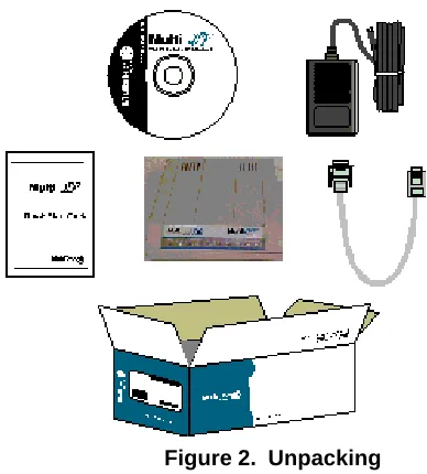
Unpacking Your MultiVOIP
Remove all items from the box (See Figure 2).
Figure 2. Unpacking Safety Warnings
Caution: Danger of explosion if battery is incorrectly replaced.
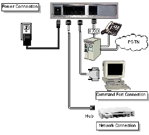
Cabling Your MultiVOIP
Cabling your MultiVOIP involves making the proper
connections for power, the command port, the FXO/PBX or PSTN system, and the Internet. Figure 3 shows the back panel connectors and the associated cable connections. The following procedure details the steps necessary for cabling your MultiVOIP.
2. Connect the MultiVOIP to a PC using the RJ-45 to DB9 (female) cable provided with your unit. Plug the RJ-45 end of the cable into the Command port of the MultiVOIP and connect the other end to the PC serial port you are using. See Figure 3.
3. Connect a network cable to the Ethernet connector on the back of the MultiVOIP. Connect the other end of the cable to your network.
4. Connect an RJ-11 cable to the Voice/Fax Channel connector on the back of the MultiVOIP and the other end to the PSTN or FXO/PBX port.
5. Turn on power to the MultiVOIP by setting the power switch on the right side panel to the On position. Wait for the Boot LED on the MultiVOIP to go off before
proceeding. This may take a couple of minutes.
Note: If the Ethernet connection is not active, none of the
Software Installation
This section covers software installation. Additional information on the MultiVOIP software is provided in the User Guide supplied with your MultiVOIP.
Note: If you are installing a MultiVOIP behind a firewall, you
need to add the following UDP ports to your firewall. 900 Signaling Information 5004 RTP Packets 5000 Status Information 5005 RTCP Packets
Refer to your firewall user documentation to enter and open these ports.
1. Make certain that your MVP120 has been properly cabled and that the power is turned on.
Note: If the Ethrenet connection is not active, none of the
LEDs will be on after booting. This unit does not have a Power LED.
If the Multi-Tech Installation CD window does not appear automatically, click My Computer, then right-click the
CD-ROM drive icon, click Open, then click the Autorun icon.
3. When the Multi-Tech Installation CD window displays, click the Install Software icon.
3a. Click Install Software.
3b. Check Proprietary, and then click OK. 4. The MultiVOIP Welcome window displays.
5. Follow the on-screen instructions to install your MultiVOIP software.
6. The Setup dialog box enables you to select the COM port of your PC that is connected to the Command port of the MVP120. From the Select Port list, select the COM port of your PC. Click OK to continue.
8. The following message displays.
Click No to continue.
9. In the Program group, double-click Upgrade Software. This loads the Proprietary software.
10. The following message displays.
Click Yes to continue.
Configuring the Host MultiVOIP
The following steps provide instructions for configuring your MVP120. The configuration sequence includes IP Protocol default setup, Channel setup, and Phone Directory Database setup.
12. The IP Protocol Default Setup dialog box displays.
The default Frame Type is TYPE_II. If this does not match your IP network, change the Frame Type by selecting SNAP from the Frame Type list. The available Frame Type choices are TYPE_II and SNAP.
13. In the Ethernet group, enter your unique LAN IP address in the IP Address box, then enter the Subnet Mask and
Gateway Address for your LAN in the corresponding
boxes.
The IP address is your unique LAN IP address, and the Gateway address is the IP address of the device connecting your MultiVOIP to the Internet. Click OK when you are finished.
For FXO-to-FXO communications, you can enable a specific FXO Disconnect: Fix Current Loss, Tone
Detection, or Silence Detection. Check with your
in-house phone personnel to verify the type of disconnect to use. If Current Loss is checked, the VOIP will hangup when it detects a loss of current on the FXO/phone port. For Tone Detection, select from the drop down list box one or two tones that will cause the line to disconnect. The person hanging up the call must then press the key or keys that produce those tones to hang up a call. For
Silence Detection, select One Way or Two Way. Then
enter in the Silence Timer box the number of seconds of silence before disconnect. The default value of 15 seconds may be shorter than desired for your application.
To dedicate the local voice/fax channel to a remote voice/ fax channel, (so you will not have to dial the remote channel) select the Auto Call Enable check box. Enter the phone number of the remote VOIP in the Phone
Number box.
17. The Fax group enables you to select the maximum baud rate for faxes and adjust the fax volume. If you do not plan to send or receive faxes on a given voice/fax channel, you can disable faxes in the Fax group.
18. The Miscellaneous group lets you set voice/fax advanced features by clicking (checking) Silence Compression,
Echo Cancellation, or Forward Error Correction.
The Silence Compression option defines whether silence compression is enabled for the voice channel. If silence compression is enabled, the MVP120 will not transmit voice packets when silence is detected, thereby reducing the amount of network bandwidth used by the voice channel.
The Echo Cancellation option defines whether echo cancellation is enabled for the voice channel. If echo cancellation is enabled, the MVP120 will remove echo which improves the quality of sound.
23. Click the Regional Tab to change the Tone Pairs and to select your country/region from the Country/Region list.
The Tone Pairs group enables you to select and modify the parameters. Click OK when finished.
Click OK. The upgrade takes several minutes to complete.
24. From the Program group, double-click MultiVOIP
In the Station Information group, enter the unique phone number of the local device connected to Channel 1 in the
Phone Number box. For example phone number 101.
26. The Description is optional, but can be useful in associating the channel to the extension.
27. Enter the Voice Channel number corresponding to the phone number entered.
28. Click the Permit Hunting box if you want calls to roll over to a second voice/fax channel on an 2, 4, or 8-port client answering MultiVOIP when the first channel is busy.
Note: Hunting will work between channels on the same
MultiVOIP. However, hunting between channels on
separate MultiVOIPs is not supported in proprietary mode.
Note: The Host MultiVOIP must have a static IP address
that the remote MultiVOIP can reference to obtain a downloaded copy of the host phone directory database. 29. In the MultiVOIP Identification group, enter the IP
address of the Host MultiVOIP in the IP Address box. Then obtain the 12-digit Node ID# (0008005xxxxx) from the ID plate on the back panel of the MultiVOIP and enter this number in the Ethernet Node ID box. If the ID plate is missing or damaged, you can also Telnet to the
MultiVOIP and, on the MultiVOIP Telnet Server menu enter
1 to advance to the Main Menu, then enter 3 for System
30. Click OK and you are returned to the Phone Directory
Database dialog box, which now includes phone number
31. Click Add and the Add/Edit Phone Entry dialog box displays again.
32. Enter the phone number for the remote MultiVOIP in the
Station Information group Phone Number box. For
example, 102.
33. Enter a description for the remote MultiVOIP phone number in the Description box.
Note: If the remote MultiVOIP is located behind a proxy
server that uses a dynamically assigned IP address, select
Dynamic (disabling Static IP Address) and leave the IP
Address box blank. The Host MultiVOIP will learn the IP address when it is contacted by the remote MultiVOIP. 34. Enter the IP address of the remote MultiVOIP in the IP
36. When you have finished, click OK. On the Main menu, click Download Setup.
38. After the setup is written to the MultiVOIP, the unit is rebooted.
39. Verify that the BOOT LED on the MultiVOIP is off after the download is complete. This may take several minutes as the MultiVOIP reboots.
Note: If the Ethernet connection is not active, none of the
LEDs will be on after booting. This unit does not have a Power LED.
40. You are returned to your MultiVOIP folder which is open and visible on your desktop.
Configuring the Client MultiVOIPs
If you are installing a MultiVOIP behind a firewall, you need to add the following UDP ports to your firewall.
900 Signaling Information 5004 RTP Packets 5000 Status Information 5005 RTCP Packets
Refer to your firewall user documentation to enter and open these ports.
1. Disconnect the PC from the command port of the Host MultiVOIP and connect it to the command port on the Client MultiVOIP.
2. From your desktop, click Start | Programs I MultiVOIP I
Upgrade Software. The following dialog box displays.
4. In the Port Address group, enter the IP Address and IP
Mask. In the Gateway Address group, enter the gateway
IP address for the client unit.
The IP address is your unique LAN IP address, and the Gateway address is the IP address of the device connected to the Internet/Intranet.
Click OK when you are finished. The Channel Setup dialog box displays.
In the Max Dial Digits box, enter the maximum number of digits allowed when dialing a phone number. The default setting is 5. In the Inter Digit Time box, enter the maximum amount of time between dialed digits in milliseconds that the unit will wait before mapping the dialed digits to an entry in the Phone Directory Database. If too much time elapses between digits and the wrong numbers are mapped, you hear a rapid busy signal. If this happens, hang up and dial again. This option is available for all interface types. In the Flash Timer box, enter the time, in milliseconds, for the duration of flash hook signals output on the interface.
For FXO-to-FXO communications, you can enable a specific FXO Disconnect: Current Loss, Tone
Detection, or Silence Detection. Check with your
in-house phone personnel to verify the type of disconnect to use. If Current Loss is checked, the VOIP will hang up when it detects a loss of current on the FXO/phone port. For Tone Detection, select from the drop down list box one or two tones that will cause the line to disconnect. The person hanging up the call must then press the key or keys that produce those tones to hang up a call. For
To change the voice coder, select the new voice coder entry from the Voice Coder list.
If you changed the voice coder, ensure that the same voice coder is used on the voice/fax channel you are calling. Otherwise, you will always get a busy signal.
Note: If Automatic Coder is selected, enter the
b o x b o x .
In the Database Type group, click the Client option. The
Host IP Address box becomes active
17. Click Download Setup to write the new configuration to the client unit. The Save Setup dialog box displays.
18. Select the Save Current Setup as User Default
Configuration check box and click OK. After the setup is
written to the MultiVOIP, the unit reboots.
19. Verify that the Boot LED on the MultiVOIP is off after the download is complete. This may take several minutes as the MultiVOIP reboots.
20. You are returned to the main menu. Your MultiVOIP is operational at this time.
Deploying the VOIP Network
Deploying the VOIP network involves the VOIP Administrator developing the VOIP Dialing Directory and deploying the pre-configured client MultiVOIPs to their remote sites. The remote site administrators need only connect power to the pre-configured MultiVOIP, connect it to their Ethernet LAN and predefined telephone equipment, and then wait for the phone directory database to be downloaded.
Perform the following procedure to deploy your VOIP network.
VOIP Administrator
1. Create your VOIP Dialing Directory based on your Phone Directory Database for the numbers to connect the MultiVOIPs to your VOIP network and the telephone extension number you need to connect the Voice/Fax channels. A sample VOIP Dialing Directory is provided below for your consideration and use.
VOIP Dialing Directory
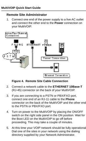
Remote Site Administrator
1. Connect one end of the power supply to a live AC outlet and connect the other end to the Power connection on your MultiVOIP.
Figure 4. Remote Site Cable Connection
2. Connect a network cable to the ETHERNET 10Base-T (RJ-45) connector on the back of your MultiVOIP. 3. If you are connecting to a PSTN or PBX/FXO port,
connect one end of an RJ-11 cable to the Phone
connector on the back of the MultiVOIP and the other end to the PSTN or PBX/FXO port.
Limited Warranty
Multi-Tech Systems, Inc. (“MTS”) warrants that its products will be free from defects in material or workmanship for a period of two years from the date of purchase, or if proof of purchase is not provided, two years from date of shipment. MTS MAKES NO OTHER WARRANTY, EXPRESSED OR IMPLIED, AND ALL IMPLIED WARRANTIES OF MERCHANTABILITY AND FITNESS FOR A PARTICULAR PURPOSE ARE HEREBY DISCLAIMED. This warranty does not apply to any products which have been damaged by lightning storms, water, or power surges or which have been neglected, altered, abused, used for a purpose other than the one for which they were manufactured, repaired by the customer or any party without MTS’s written authorization, or used in any manner inconsistent with MTS’s instructions.
MTS’s entire obligation under this warranty shall be limited (at MTS’s option) to repair or replacement of any products which prove to be defective within the warranty period, or, at MTS’s option, issuance of a refund of the purchase price. Defective products must be returned by Customer to MTS’s factory transportation prepaid.
MTS WILL NOT BE LIABLE FOR CONSEQUENTIAL DAMAGES AND UNDER NO CIRCUMSTANCES WILL ITS LIABILITY EXCEED THE PURCHASE PRICE FOR DEFECTIVE PRODUCTS.