ISSN(Online): 2320-9801
ISSN (Print): 2320-9798
International Journal of Innovative Research in Computer
and Communication Engineering
(An ISO 3297: 2007 Certified Organization)
Vol. 3, Issue 9, September 2015
Advanced Vehicle System Based on Embedded
Technology
S.Valarmathy
1, R.Ramani
2, S.Selvaraju
3, G.Suresh Kumar
4Associate Professor, Dept. of ECE, V.M.K.V Engineering College, Salem, Tamil Nadu, India1
Associate Professor, Dept. of ECE, V.M.K.V Engineering College, Salem, Tamil Nadu, India2
Associate Professor, Dept. of ECE, V.M.K.V Engineering College, Salem, Tamil Nadu, India3
Associate Professor, Dept. of ECE, V.M.K.V Engineering College, Salem, Tamil Nadu, India4
ABSTRACT: Presently the majority of the public having a vehicle, theft is happening on parking place and uncertainty
places. The vehicle safety is fundamental for every person. Advanced Vehicle system based on embedded is used to install in vehicle, which track the place or location of the vehicle and locking the motor as well as monitor the fuel and distance of the front vehicle while driving. This system used to track the vehicle, fuel monitoring and announce the distance of the front vehicle. The places of the vehicle come to known by Global Positioning system and Global system mobile communication systems. These systems continuously study a moving Vehicle and report the condition. While the theft branded, the responsible person sending SMS to the controller unit, after that controller issue the needed control signals to bring to a halt the car motor and sending SMS to the authorized person and police station about status of the location of the vehicle. Authorized person want to send the password to controller to start again the vehicle and open the door. This is more secured; prevent the accident, consistent and low cost.
KEYWORDS: AdvancedVehicle system, tracking, Locking, fuel, distance, ultrasonic, Microcontroller, GPS, GSM
I. INTRODUCTION
In the past decades, India has progress such a massive rate that many companies have effectively established at this position. These companies are bringing a vast amount of labor force with them. They are arranging transportation to such a vast mass is a bulky job involving many details. Generally, this transport is arranged during the local transport vendor on once a year agreement basis, just now happen mishaps, such as stealing, rape etc. The increase of satellite communication technologies is easy to discover the vehicle locations with no trouble. Advanced Vehicle systems based on embed technology bring to everyday life. Nowadays most of the people GPS used in cars, ambulances and police vehicles. All the available technologies is used to maintain the tracking vehicle place and monitoring various parameter.
The GSM/GPS system is very important everyone in day-to-day life, which has integrated both GSM and GPS technologies. It is necessary due to the group of applications both GSM and GPS systems that the wide usage by millions of citizens all over the world [1]. These systems intended for use in land production and transport offer real-time information for example place, speed and predictable arrival real-time of the user is moving vehicle in the concise and mobile formats. This system may be useful for communication development in the middle of the two points.
ISSN(Online): 2320-9801
ISSN (Print): 2320-9798
International Journal of Innovative Research in Computer
and Communication Engineering
(An ISO 3297: 2007 Certified Organization)
Vol. 3, Issue 9, September 2015
of the tank through ultrasonic sensor. The advance vehicle systems are acknowledged in customer vehicles as a theft prevention and recovery the vehicle. While the theft is come to know, the controller sends SMS to the respective owner. After that, the respective people send SMS to controller; issue the necessary signals to lock the motor. In this paper, the review related technology in section II. The advance vehicle system and locking systems carried out in section III. The debugging and testing process, conclusion is in section IV and V respectively.
II. SURVEY OF THE RELATED WORKS
In this paper [2], GSM and GPS network developed based on hardware and software. The designed GSM/GPS based System has two parts, mobile unit and one more is control station. These system is connected varies part devices such as, data transmit and receive of data between the mobile section and control section are work successfully. These results are well matched with GPS technology.
In this paper [3], vehicle-tracking system is introduced, which is installed in vehicle to authorize of the owner or police to identify the way of the vehicle place or location. In this paper, vehicle-tracking system designed based on GSM and GPS technology. This system implemented based on embed system. This system is always monitoring the moving Vehicle and report of the condition.
In [4], the face of the driver is identified by FDS system, and compare with the predefined face. Then Face Detection System acquires images by one small web camera installed in the car. FDS system compared the obtain images with stored images. If the images are not match, then system send information to the owner. The owners acquired image of the robber in mobile phone and mark out the place using GPS. The location of the car and speed is display on mobile phone of the owner. This system can be alert of the robber images as well as the car location and discover the hijacker’s image. These systems may be useful in our life.
In [5], the vehicle cabin protection and safety implemented based on embed system by modified the offered modules. This technique can monitors the level of the toxic gases, like alcohol, CO, LPG within the vehicle provide alert information at the same time as alarm for the period of the dangerous situation. The information can sends to the allowable person through GSM. In this technique is used to detect the immobile obstacle in front vehicle and the vehicle is stopped. These systems avoid the accident due to any static obstacles.
In [6], they have a designed and built on a real-time visual tracking system for vehicle protection applications. In this paper, built a new feature-based vehicle tracking, automatically identify and track the moving objects. The system can segment features of movable objects from the moving background. These system offers a collision caution on real-time. They are using an image sensor [CMOS] and NMOS embed processor architecture. The results of this paper provided information of collision word of warning in urban route with speed about sixty km/hour both at day and night period.
In [7], the SMS and GSM based remote monitoring system is implemented. This paper, the GSM network is an in-between for transmitting the remote signal. This device has two main parts, monitoring the centres and the remote monitoring centres. The monitoring station has two-section, computer and communication module of GSM. The software monitor center, the remote monitoring station are implemented by using VB. In [7], the result of this show that the system can observe, control communication and the monitoring center along with the remote monitoring stations.
In [8], the proposed method of tracking system based on cloud compute infrastructure. The fuel level and speed of the vehicle is monitor using ultrasonic sensors. All the data is transfer to cloud computing server by Global position system. The vehicles is having GPS antenna to identify the location of the place. The alcohol sensor installed in the vehicle to monitor the drunk and drive status. The proposed technologies appreciably avoid the accidents in highways.
ISSN(Online): 2320-9801
ISSN (Print): 2320-9798
International Journal of Innovative Research in Computer
and Communication Engineering
(An ISO 3297: 2007 Certified Organization)
Vol. 3, Issue 9, September 2015
III. PROPOSED METHOD
In this proposed work, a new method of advanced vehicle system is implemented, which is used to track the theft vehicle by using GPS, GSM technology and also provide voice alarm according to the distance of the front vehicle and fuel status of the tank. If any disruption occurred in all surface of the door, then IR sensor sense the interrupt signals and send to the system controller. Then controller provides communication about the location of vehicle to owner. When SMS send to controller, the required control signals send to the engine motor. After receiving the message, engine motor speed is slowly decreases and motor come to off position then all doors are locked. Again, to start the engine, permitted person want to enter passwords. The tracking of vehicle location is uncomplicated and doors locked automatically, thus thief cannot move away from the car. The front vehicle of the distance is measured and monitors the fuel level of the tank by ultra-sonic sensor.
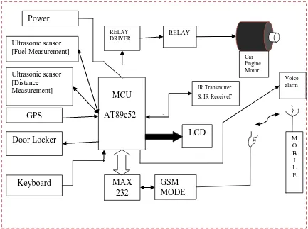
A. Block Diagram
The advance Vehicle system based on embedded of the block diagram is shown in Fig.1. It is consists various blocks such as the regulated power supply, sensor, keyboard, GPS, GSM, 8952 controller, Ic MAX232driver, relay driver, Transmitter, receiver, door locker and LCD. The GSM board has a valid SIM card with adequate recharge amount to generate outgoing calls. The circuits powered by +5v Dc only.
Fig. 1. Block diagram of Advanced Vehicle System
Power
supply
MCU
AT89c52
RELAY DRIVERRELAY
GPS
LCD
M O B I L E IR Transmitter
& IR Receive
r
Door Locker
Keyboard
GSM
MODE
M
MAX
232
Voice alarm Car
Engine Motor
ISSN(Online): 2320-9801
ISSN (Print): 2320-9798
International Journal of Innovative Research in Computer
and Communication Engineering
(An ISO 3297: 2007 Certified Organization)
Vol. 3, Issue 9, September 2015
Fig. 2. Power Supply
B. Circuit descriptions
The regulated power supply section is used to produce the required +5v and +12v. The full-wave rectifier comprise diodes D1 through D4, which is used to convert AC to DC signal and filtered by capacitor C1. The voltage is regulated by +5v, +12v through ICs 7812 and 7805. Light Emitting Diode [LED1] acts as a power indicator and Resistor R1 limits the current through LED. The regulated power supply unit is shown in Fig.2.
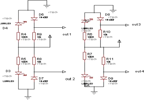
Fig. 3. Door Sensor Circuit
ISSN(Online): 2320-9801
ISSN (Print): 2320-9798
International Journal of Innovative Research in Computer
and Communication Engineering
(An ISO 3297: 2007 Certified Organization)
Vol. 3, Issue 9, September 2015
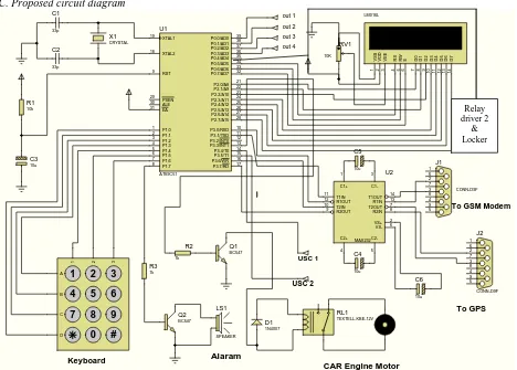
C. Proposed circuit diagram
C1 33p C2 33p C3 10u R1 10k X1 CRYSTAL XTAL2 18 XTAL1 19 ALE 30 EA 31 PSEN 29 RST 9 P0.0/AD0 39 P0.1/AD1 38 P0.2/AD2 37 P0.3/AD3 36 P0.4/AD4 35 P0.5/AD5 34 P0.6/AD6 33 P0.7/AD7 32 P1.0 1 P1.1 2 P1.2 3 P1.3 4 P1.4 5 P1.5 6 P1.6 7 P1.7 8 P3.0/RXD 10 P3.1/TXD 11 P3.2/INT0 12 P3.3/INT1 13 P3.4/T0 14 P3.7/RD 17 P3.6/WR 16 P3.5/T1 15 P2.7/A15 28 P2.0/A8 21 P2.1/A9 22 P2.2/A10 23 P2.3/A11 24 P2.4/A12 25 P2.5/A13 26 P2.6/A14 27 U1 AT89C51 D 7 1 4 D 6 1 3 D 5 1 2 D 4 1 1 D 3 1 0 D 2 9 D 1 8 D 0 7 E 6 R W 5 R S 4 V S S 1 V D D 2 V E E 3 LCD1 LM016L RV1 10K T1IN 11 R1OUT 12 T2IN 10 R2OUT 9 T1OUT 14 R1IN 13 T2OUT 7 R2IN 8 C2+ 4 C2-5 C1+ 1 C1-3 VS+ 2 VS- 6 U2 MAX232 1 6 2 7 3 8 4 9 5 J1 CONN-D9F Q2 BC547 R3 1k LS1 SPEAKER C4 10u C5 10u C6 10u Q1 BC547 R2 1k RL1 TEXTELL-KBE-12V D1 1N4007
To GSM Modem
CAR Engine Motor Alaram 1 6 2 7 3 8 4 9 5 J2 CONN-D9F To GPS
1 2 3
4 5 6
7 8 9
0 #
1 2 3
A B C D Keyboard out 1 out 2 out 3 out 4 USC 1 USC 2
Fig. 4. Circuit Diagram of the Advanced Vehicle System
The VR means variable resistor is used to control the contrast of LCD. Resistor 10k ohms limit the currents of the backlight LCD. Port P3.0, P3.1 is used to interface the RFID reader using Max232, GSM Modem is used to interface by Max232. Port 1 pins are connected to keyboard. The GSM and GPS are used to connect through RXD and TXD. The port P0.0 - P0.3 is used to connect 4 sensors for detecting the illegal person. The P1.7 is used to connect bipolar transistor BC147 for alarms, Pin number P3.3 is used to connect the car engine motor. If any disruption occurs in any side of the door, sensors sense the signals and send to the controller, then the controller provides message to car owner. While SMS send to controller, the control signals given to the engine motor. The car motor speed is decreases and comes to off. After that, all the doors are locked. To release the door and restart the car allowed person needs to enter valid passwords. In this techniques, tracking of vehicle location and doors are locked automatically thereby thief cannot escape from the car. In Port 0, the number Pin P0.4 is connected to transistor Q3 drive into saturation, and relay energizes to lock or unlock the door lock. Pin 14 and Pin 15 is used to connected ultrasonic transmitter and receiver sensor. It is used to measure the distance of the front vehicle and measure the fuel level in the tank. This circuit is shown in the Fig.5
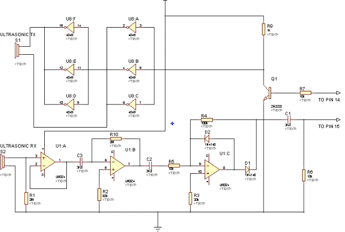
D. Distance Measurement Using Ultrasound Sensor
There are so many ways to measure the distance without contact. The ultrasonic sensor is one of the most valuable devices, which is used to measure the distance between two points with help of ultrasonic waves at 40 kHz. Ultrasonic transducers can measure the quantity of time taken for a pulse of sound waves to travel a particular surface and returns the reflected echo. This circuit used to calculate the distance based on the speed of sound at 25°C ambient temperature.
Relay driver 2
ISSN(Online): 2320-9801
ISSN (Print): 2320-9798
International Journal of Innovative Research in Computer
and Communication Engineering
(An ISO 3297: 2007 Certified Organization)
Vol. 3, Issue 9, September 2015
The Ultrasound Sensorcan measure distance up to 2.5 meters or 8.12 feet. The circuit consists of two 40 kHz ultrasonic transducers (transmitter and receiver), inverter, current buffer ULN2003, operational amplifier and transistors.
In this circuit, a 40kHz transducer is used for the measurement of air medium. The velocities of the sound - waves are around 330 m/s at 0°c and vary with temperature. It travels to the object in air and another ultra-sonic transducer picks up the echo signal. The weak signal is received and amplified by receiver. The Weak signals of the echoes also arise due to the signals directly received during the surface lobes. These are unnoticed, as the real echo received alone would give the correct distance. The controller used to produce 40 kHz sound pulses. When the echo arrives it reads, finds the time taken in microseconds and from travel of sound waves.
Fig. 5. Distance Measurement Using Ultrasonic Sensor Circuit
E. Fuel measurement using Ultrasound Sensor
Ultrasonic sensors are characterized by an low-cost and by the choice of being used in environment situations where it is impossible to use more complex sensors as camera, laser devices and optical sensors [10]. In this work, NT-TS601, ultrasonic electric telemeter modules employed as ultrasonic transmitter and receiver [11], [12].
This module can be able to measure a distance within 0.03-2.5M efficiently and transform the data into impulse of discrete width. At first 5us, pulse applies through the pin SIG of module, which is triggers, the transmitter to produce 40 kHz ultra-sound signal string. Now the receiver catches the reflected wave, it generate a high pulse width that correspond to the time, the signal takes reflected back. By using this width, we can measure the distance as well as the fuel level.
Distance Calculation: d1 = Pulse Width (us) * 32 Distance = d1/100 cm Decimal Point = d1 Mod 10
Total distance = (Distance+ Decimal Point) cm Fuel Amount computation:
ISSN(Online): 2320-9801
ISSN (Print): 2320-9798
International Journal of Innovative Research in Computer
and Communication Engineering
(An ISO 3297: 2007 Certified Organization)
Vol. 3, Issue 9, September 2015
LITRE1 = Distance*LITRE_VALUE (preset value) \inch
LITRE2 = d2*LITRE_VALUE/100, Total Litre = LITRE1+LITRE2
This computation is calibrated for 10 MHz crystal oscillator. By using ultrasound sensor module and the calibrated computation given the accuracy of 95-97% can be achieved [13].
F. GPS technology
The GPS is one of the valuable satellite-based navigation systems that consist of twenty-four satellites located into specified orbit. This satellite system offers necessary information to military applications, civil and business applications around the world. This is easily available to any person with a GPS receiver. GPS device perform in any weather environment, at everyplace in the earth. There is no subscription charge for GPS utilization. The receiver of the GPS locks based on minimum 3 satellites signals approximate 2 dimensional positions. The vehicle position or location has been determined with the help of GPS; this unit can determine further information similar to, speed, and distance to destination, time and other. GPS receiver is used for this research process to identify the vehicle location and offers information to responsible person by GSM technology [14] [15].
Fig. 6. GPS module
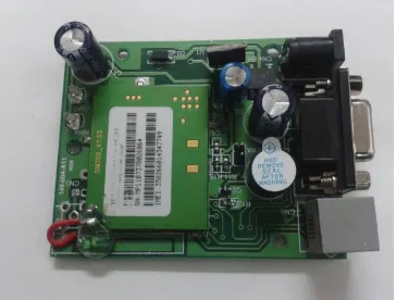
G. GSM modem SIM300 V7.03
The GSM modem is a specific type of device, which accepts a SIM card operate on a subscriber’s mobile number over a network, as a cellular phone. Modem sim300 is triband GSM/GPRS locomotives that perform on EGSM900MHz, DCS1800MHz and PCS1900MHz frequencies. GSM Modem is used as a RS232-logic level compatible, i.e., it various from -3v to -15v as logic high and +3v to +15 as logic low.MAX232 is used to convert TTL into RS232 logic level converter is used between the microcontroller and the GSM board. The microcontroller signal is sent to the GSM modem through pin 11 of max232. The pin2 of the GSM modem received the signal from microcontroller. The GSM modem transmits the signals from pin3 to the microcontroller through MAX232 [9].
ISSN(Online): 2320-9801
ISSN (Print): 2320-9798
International Journal of Innovative Research in Computer
and Communication Engineering
(An ISO 3297: 2007 Certified Organization)
Vol. 3, Issue 9, September 2015
IV. DEBUGGING AND TESTING PROCESS
An advanced vehicle system based on embedded system is a complicated process that involves hardware and software interfacing. The design of an advanced vehicle system based on embedded require more skill to use debugging and testing tools to hand. The debugging and testing of advanced vehicle system based on embedded divided into two groups: software and hardware tool parts. A software simulator is a used for program running on a self-determining hardware and simulates the embedded c programs. Simulators offer the small cost of development tools for micro controller based systems and many companies provide free simulator programs.
The software program is written in assembly language program or c program, which is compiled using Keil software. The hex code is generate with help of compiler, and stored in the computer. The hex code of the program is loaded into the AT89C52 microcontroller by using Universal programmer [14].
A. Hardware Assembling and Testing
The First step of hardware assembly needs to make PCB layout for the given advanced vehicle system circuit using Orcad. After completed the PCB work then the following process is necessary to complete the project implementation. 1. Assemble all the components on the PCB board based on the given circuit. Transmitter and Receiver section of the modem is connected to pins 13 and 14 of MAX 232, and put in a valid SIM in the GSM modem.,
2. GPS module Connected according to the circuit diagram. 3. This project successfully implemented and tested by us. 4. This system is useful and safe for car owners.
V. CONCLUSION
In this paper work, a new method of advanced vehicle system based on embedded is implemented, which is used to track the location of the theft vehicle by using GPS, GSM technology and also provide voice alarm according to the distance of the front vehicle and fuel status of the tank. If any disruption occurred in all surface of the door, then IR sensor sense the interrupt signals and send to the system controller. Then controller provides communication about the location of vehicle to owner. When SMS send to controller, the required control signals send to the engine motor. After receiving the message, engine motor speed is slowly decreases and motor come to off position then all doors are locked. Again, to start the engine, permitted person want to enter passwords. The tracking of vehicle location is uncomplicated and doors locked automatically, thus thief cannot move away from the car. In this system gives voice alarms about the distance of the front vehicle with the help of ultrasonic sensor and monitor the fuel of the tank
REFERENCES
1. Chen, H., Chiang, Y. Chang, F., H. Wang, H. (2010). Toward Real-Time Precise Point Positioning: Differential GPS Based on IGS Ultra Rapid Product,SICE Annual Conference, The Grand Hotel, Taipei, Taiwan August 18-21.
2. Asaad M. J. Al-Hindawi, Ibraheem Talib, “Experimentally Evaluation of GPS/GSM Based System Design”, Journal of Electronic Systems Volume 2 Number 2 June 2012
3. Kunal Maurya , Mandeep Singh , Neelu Jain , “Real Time Vehicle Tracking System using GSM and GPS Technology- An Anti-theft Tracking System,” International Journal of Electronics and Computer Science Engineering. ISSN 2277-1956/V1N3-1103-1107
4. Vikram Kulkarni & Viswaprakash Babu, “embedded smart car security system on face detection’, special issue of IJCCT,ISSN(Online):2231-0371, ISSN(Print):0975-7449,volume-3, issue-1
5. V.Ramya, B. Palaniappan, K. Karthick, “Embedded Controller for Vehicle In-Front Obstacle Detection and Cabin Safety Alert System”, International Journal of Computer Science & Information Technology (IJCSIT) Vol 4, No 2, April 2012.
6. Kai-Tai Song, Chih-Chieh Yang, of National Chiao Tung University, Taiwan, “Front Vehicle Tracking Using Scene Analysis”, Proceedings of the IEEE International Conference on Mechatronics & Automation 2005.
7. Chen Peijiang, Jiang Xuehua, “Design and Implementation of Remote monitoring system based on GSM,” vol.42, pp.167-175. 2008.
8. Albert Alexe, R.Ezhilarasie, “Cloud Computing Based Vehicle Tracking Information Systems”, ISSN: 2229 - 4333 ( Print ) | IS SN : 0976 - 8491 (Online ) IJCST Vol. 2, Iss ue 1, March 2011
9. R.Ramani, S.Selvaraju, S.Valarmathy, R.Thangam B.Rajasekaran, “water-level monitor for bore well and water tank based on GSM”, International Journal of engineering science and technology (IJEST), ISSN: 0975-5462, volume4-N0:10, october2012.
10. G. Bucci, “Numerical method for transit time measurement in ultrasonic sensor applications,” IEEE Trans on Instrumentation and Measurement, vol. 46, no. 6, pp. 1241-1246, 1997.
ISSN(Online): 2320-9801
ISSN (Print): 2320-9798
International Journal of Innovative Research in Computer
and Communication Engineering
(An ISO 3297: 2007 Certified Organization)
Vol. 3, Issue 9, September 2015
12. S. H. Baek and Y. H. Kim, “Design of multi position tracking system using ultrasonic sensor module,” in Proc. Symposium on Ultrasonic Electronics, 2010, vol. 31, pp. 479-480.
13. Sadeque Reza Khan, Arifa Ferdousi, Siddique Reza Khan, Real Time Generator Fuel level Measurement Meter Embedded with Ultrasound Sensor and Data Acquisition System’’, Journal of Automation and Control Engineering Vol. 1, No. 4, December 2013.
14. R.Ramani, S.Valarmathy, Dr.N.Suthanthira Vanitha, S.Selvaraju, M.Thirupathi, R.Thangam, “Vehicle Tracking and Locking System Based on GSM and GPS”, I.J. Intelligent Systems and Applications(IJISA), 2013, 06, 61-69Published Online May 2013 in MECS, DOI: 10.5815/ijisa.2013.06.08.
15. R.Ramani, S.Valarmathy, S.Selvaraju, P.Niranjan, “Bank locker Security system based on RFID and GSM technology”, International Journal of computer and applications (IJCA), USA, and ISSN: 0975-8887, volume57-N0.18,November2012.
BIOGRAPHY
S.Valarmathy is working as Associate Professor in the department of electronics and communication engineering, V.M.K.V.Engineering College, Salem. She has received M.Sc., in Applied Electronics from Cheran arts and science, Bharthiyar University, Coimbatore in 2002, M.E in Advanced Communication Systems from V.M.K.V.Engineering College, Vinayaka Missions University, Salem 2006. She has 16 international journals published. Her area of research interests includes Image Processing, Embedded System.
R.Ramani is working as Associate Professor in the Department of Electronics and Communication Engineering, V.M.K.V. Engineering College, Salem. He has received B,E degree in Electronics and Communication Engineering from Government College of Engineering, Anna University, Chennai in 2006 and M.E in Communication Systems from Sona college of technology, Anna University, Chennai in 2008. He has 17 international journals published. His area of research interests includes Embedded Systems, Image Processing and VLSI.
S.Selvaraju is working as Associate Professor in the department of Electronics and Communication engineering, V.M.K.V.Engineering College, Salem. He has received B.E, in electronics and communication engineering from Kongu Engineering College, affiliated to Bharthiyar University, Coimbatore in 1989 and M.E in Applied Electronics from V.M.K.V.Engineering College, affiliated to Anna University and Salem 2005. Her area of research interests includes Embedded Systems and Networks Communication.