Design and Development of Hydraulic Bearing
Puller and Pusher
Keshvala Jaydip 1, Kahar Harshal 1, Patel Harsh 1, Rakesh R Patel 2
Diploma Student, Department of Mechanical Engineering, Tapi Diploma Engineering College, Surat, Gujarat, India1 Lecturer, Department of Mechanical Engineering, Tapi Diploma Engineering College, Surat, Gujarat, India2
ABSTRACT: Now a day’s hydraulic system plays very important role in almost all the application in automobile industries, small service centre, aircraft industries are used where precision is required. Traditional method of bearing removal or installation is hammering but unnecessary hammering causes several damages to the bearing as well as shaft due to which chances of failure of bearing may possible. The modification is to give less human effort, simplify the operation without damaging shaft and bearing. The hydraulic bearing puller and pusher work on the principle of Pascal’s law.
KEYWORDS: Bearing puller, Bearing pusher, Pascal’s law, Hydraulic jack, Principle of hydraulics, CAD model.
I. INTRODUCTION
In hydraulic bearing puller and pusher is a special arrangement which will be attached to a hydraulic jack, bearing clamp and shaft clamp respectively. First we use hydraulic jack. There after the hydraulic jack is connected to the bearing clamp with the help of pusher arrangement. Then the shaft clamp is attached with the help of stud rod which is connected to the jack plate. In order to maintain geometrical precision and the surface integrity of ball and roller bearing raceways and rolling elements , it is mandatory that care in storage , handling and installation be observed. The hydraulic bearing puller and pusher perform both pulling and pushing operation safely and without harming bearing surfaces. The Hydraulic Bearing Puller and Pusher was developed by Rakesh Y. Suryawanshi in which [1] the machine is a arrangement of for removing as well as installing bearing on the shaft. Hydraulic pulling consists of adjustable mechanical jaw puller inbuilt with the hydraulic jack. When pump operated, plunger comes outside. Then mechanical jaws adjusted bellow the bearing and again operate the pump.
II. OBJECTIVES
By using hydraulic bearing puller equal and consistent force is applied so that bearing can easily removed from the shaft without damaging surface finish of the shaft. Same as in mounting the bearing on the shaft in reverse fashion.
Less human effort is required.
Time is reduced.
Bearing and shaft are not damage during mounting and removal.
III.DISCRIPTION
1. Hydraulics’:
The word hydraulics’ concerned with study of behaviour of water at rest and at motion i.e. behaviour of liquids. Hydraulics’ includes properties, advantages and applications of liquids. The two main scientists give the direction to forward, one is Daniel Bernoulli and another is Blasé Pascal. Bernoulli's conducted an experiment on fluid flow and gives fluid flow equation to the world and at same period Pascal developed science of hydraulics.
2. Pascal’s law :
Fig. 1 Pascal’s law [2]
Pascal's law (also Pascal's principle or the principle of transmission of fluid-pressure) is a principle in fluid mechanics states that a pressure change occurring anywhere in a confined incompressible fluid is transmitted throughout the fluid such that the same change occurs everywhere. The law was established by French mathematician Blaise Pascal in 1647–48.
According to Pascal’s Law, Pressure or intensity of pressure at a point in a static fluid will be equal in all directions. In order to understand how hydraulic system depends over Pascal’s law, we will consider following case.
As we can see in above figure, area A2 is larger as compared to area A1 hence it will require less force to lift the heavy load.
3. Bearing installation and removal basics :
Mechanical Removal, Installation And Methods
Fig.2 Manual method [2] Fig.3 Thermal method [2]
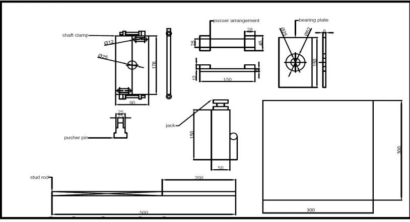
IV. WORKING AND DESIGN
Hydraulic puller and pusher perform both the operation i.e. removal of bearing and installation respectively. Hydraulic pulling consists of bearing clamp with the hydraulic jack. When jack operated, plunger comes outside. Then bearing clamp goes upward direction and bearing is installed on shaft. During operation, hydraulic jack applies continuous pressure on shaft with the help of pusher pin and remove bearing from shaft.
2. Design Consideration:
Load capacity of Hydraulic Jack (W) = 5 ton (50 KN)
Operating Pressure (p) = 80 Kgf
Lift Range (L) = 15 cm
Man effort put on handle (e) = 20Kg
Permissible tensile stress of mild steel (6t) = 120 N/mm2
No. of stroke for lifting load (n) = 150
Factor of safety = 5
Permissible shear stress of mild steel (τ) = 20 N/mm2
Permissible comp. stress of mild steel (6c) = 20 N/mm2
Permissible comp. stress of cast iron (6c) = 120 N/mm2
Permissible shear stress of cast iron (τ) = 35 N/mm2
Design of Hydraulic Jack: 1)
The material of hydraulic jack is cast iron and having capacity of 5 ton. Material used for handle and jack plate is mild steel.
Outer diameter of jack (Do) = 50 mm
Inner diameter of jack (Di) = 20 mm
Oil capacity in reservoir at bottom of jack = 200 ml
Handle attached to jack (l*b*t) = (280 mm*10 mm*8 mm)
Vertical stud rod attach to both sides diagonally to the jack plate (l) = 500 mm
Design of bearing clamp: 2)
Puller plate dimension (l*b*t) = (150 mm*90 mm*8 mm)
Upper hole on bearing clamp = 52 mm
boring height on bearing clamp = 5 mm
Hole on bearing clamp = 25 mm
Design of Shaft Clamp: 3)
Material used for shaft clamp is mild steel. During pushing operation of bearing, shaft clamp plays very important role i.e. to hold the shaft.
Diameter of shaft ( D) = 50 mm
Shaft clamp Dimension (l*b*t) = ( 180 mm*90 mm*10 mm)
Central hole on clamp plate of diameter = 50 mm
slot on clamp plate for vertical stud of diameter = 36 mm
Slot diameter = 12 mm
Design of pushing Arrangement: 4)
The material used for pusher is mild steel. Pusher is made like C frame having horizontal stripes on which two vertical strips welded at the end of horizontal strips . The two horizontal loads welded on vertical strips.
Horizontal strip dimension ( l*b*t) = ( 150 mm*25 mm*8mm)
Design of pusher pin 5)
The material used for pusher is mild steel it is use for puss shaft in bearing removing process.
Diameter of pin (D) = 15 mm
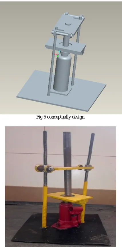
1. AutoCAD model:-
Fig 5 conceptually design
V. CONCLUSION
In order to remove and installed bearing safely, to make modification in traditional method. The modification made in installing and easy removing bearing. The purposes of modification are Simplicity of operation, removing and installation of bearing done without damaging bearing surface, compact, portable, well suited, low cost, Multifunctional ,safe ,versatile.
REFERENCES
[1] Rakesh Y. Suryawanshi, Pranay S. Ramteke, Niraj Patil, Deepak Kumar ‘Design and Fabrication of Hydraulic Bearing Puller and Pusher’ IJIRST –International Journal for Innovative Research in Science & Technology| Volume 1 | Issue 11 | April 2015
[2] https://www.processingmagazine.com/bearing-installation-removal-basics/ [3] https://www.clippard.com/cms/wiki/pascals-law
![Fig. 1 Pascal’s law [2]](https://thumb-us.123doks.com/thumbv2/123dok_us/1552006.1190512/2.595.67.496.310.575/fig-pascal-s-law.webp)