Hydraulic Anti-Lock Braking System for A
Motorcycle
Nevetha R 1, Ilakkiya S N 2, Sarathy S3, Swetha S4, Deepa R5
P.G. Student, Embedded System, Bannari Amman Institute of Technology, Erode, Tamilnadu, India1 2 3 4
Associate Professor, Embedded System, Bannari Amman Institute of Technology, Erode, Tamilnadu, India5
ABSTRACT: This work presents a hydraulic anti-lock braking system (ABS) for a motorcycle. The ABS has a hydraulic modulator and an intelligent controller. The hydraulic modulator is analyzed, and then equipped on a scooter for road tests. The intelligent controller controls the hydraulic modulator by estimated vehicle velocity to calculate the slip ratio of the wheels in real time. The performance of the hydraulic modulator and intelligent controller are assessed by the hardware-in-the-loop (HIL) simulations and road tests. In HIL simulation, the ABS is tested for different initial braking velocities on roads with different adhesive coefficients. Furthermore, both HIL simulations and road tests are conducted on a one-phase pavement road and three-phase pavement road.
KEYWORDS: Anti-lock brake system; Intelligent controller; Hardware-in-the loop simulation; Real road test
I. INTRODUCTION
In recent decades, many anti-lock braking systems have been developed and installed on vehicles. However, most are designed for cars or trucks, not for motorcycles. In Asia, the motorcycle is a primary mode of transportation. Therefore, an ABS for motorcycles is needed. Generally, when motorcycles brake, those without ABSs usually trip bringing injury to riders. On wet roads in particular, riders cannot control motorcycles when the braking pressure exceeds a threshold value and the wheels lock. However, the wheels on a motorcycle equipped with an ABS would not lock during sudden braking, allowing the rider to steer the motorcycle efficiently. Moreover, an ABS on a motorcycle can reduce braking distance. However, most ABSs installed on four-wheel vehicles have hydraulic pumps and tanks. Both the size and cost of hydraulic pump and tanks limit their use on motorcycles making the ABSs installed on four-wheel vehicles unsuitable for motor cycles. This study presents an ABS for motorcycles, and tested it on a scooter. The ABS is only equipped on the rear wheel of the scooter in both HIL simulations and the road tests. The front wheel is utilized to measure vehicle velocity, which is then compared with the estimated vehicle velocity calculated by the intelligent controller. Briefly, the front wheel of a motorcycle does not go on brake in the HIL simulation or the real road test. Only the rear wheel brakes using the ABS.
II. RELATEDWORK
DESCRIPTION OF ABS SYSTEM
ABS is an electronic vehicle safety system which monitors and control wheel slip during vehicle braking and helps to improves stopping distance. When brakes are applied the vehicle and wheel speed start decreasing. However, thedecrease in vehicle speed is not always corresponding to the decrease in wheel speed. The non-correspondence between wheel speed and vehicle speed is called slip and its magnitude is represented by slip ratio (λ),
λ = * 100
Where,
R- Radius of wheel ω - Angular speed of wheel
ABS SYSTEM CONSISTS OF FOLLOWING SUBSYSTEM:
2.1Wheel Speed Sensor 2.2 ECU
2.3Hydraulic Pressure Modulator
In advanced ABS system other inputs like roll angle sensor, gyroscope sensors, acceleration sensor are used to realize advanced feature like HSA (Hill start assist), Curve traction control, cornering ABS, lateral stability control etc.
Fig.1 ABS system components
A.WHEEL SPEED SENSOR:
In case of two channels ABS system two wheel sensors are used i.e. front wheel and rear wheel. This wheel sensor continuously monitors wheel speed and it detects the rapid vehicle deceleration. These sensors are mounted near a rotating disc or in some cases toothed rings are used for Electromagneticor Hall-effect type pulse pickups and mounted directly on the rotating components of the wheel hubs. In some ABS cases, vehicle speed is estimated from wheel speed by using estimation algorithm like Kaman’s filtering, observer designing etc. Otherwise accelerometer is also used by some manufacturer.
B. ELECTRONIC CONTROL UNIT (ECU):
From fig [1], it is cleared that output of wheel speed sensors is given as input to the ECU which then calculate slip ratio andgenerate optimum braking torque in order to prevent wheel locking condition. The operation like slip comparison andvelocity estimation are performed in ECU. The generated output signal is given to the hydraulic pressure modulator.
HYDRAULIC PRESSURE MODULATOR:
III.TEXTINPAINTING
DYNAMICS OF THE TIRES ON THE GROUNDWHEN BRAKING
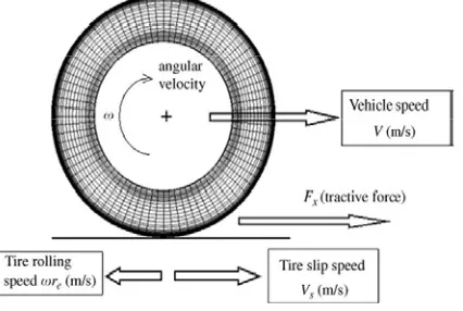
When the vehicle is running, ground forces acting on the tire are shown in Fig.2. They include the normalforce Fz, the longitudinal force Fx and the lateral force Fy. Fz comes from the weight and load of the vehicle. Its magnitude also varies due to the load transfer effect during braking.
Fig. 2Free body diagram of a single tire
The longitudinal force Fx is produced during driving and braking. The lateral force Fy helps the vehicle in turning and maneuvering, or in some cases, in resisting a side disturbance force such as the wind. There duction in braking distance depends on whether Fx can be maintained at its maximum value. During braking, the contact patch between tire and ground begins to slip. This substantially affects both the longitudinal and lateral friction coefficients. The well known parameter to represent slippage is the slip ratio.
The tire slip ratio is defined as:
λ = Vs/V = (V - ωre)/V (1)
where V is the absolute vehicle speed, Vs is the tire slip speed, re is the effective radius of the tire, and ω is the angular velocity of the tire. From the definition, one can conclude that when λ=0, the tire is in perfect rolling motion without slipping.
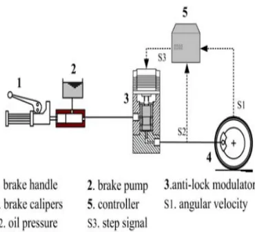
III.HYDRAULIC MODULATOR
Fig. 3. Scheme of the ABS.
At this moment, brake oil from the brake pump is separated by the hydraulic modulator. The volume of Chamber D, which is between the spool and the bottom case, is increases; thus, oil brake pressure in the brake calipers decreases. That is, the controller can reduce brake pressure by increasing the volume of chamber D or can increase brake pressure by reducing the volume of chamber D.Briefly, the controller regulates the volume of chamber D suchthat the brake pressure in the calipers conforms to the targetpressure.The target pressure is calculated by the intelligent controller.When motorcycle velocity is zero and the ABS is not in use,the spool in modulator returns to its initial position Fig. 4(a).The cylinder barrel is made by Teflon, which can lower thefriction force when the spool is moving.Generally, when an ABS is installed on a car, the brake pedal will vibrate when the hydraulic modulator adjusts braking pressure. For motorcycles, this vibration can cause a driver to lose control of the brake handle; thus, this vibration must be prevented. The hydraulic modulator in this study obstructs the brake oil out of the orifice by the spool Fig. 4(b). When the hydraulic modulator is regulated, oil pressure from the brake pump and brake calipers are isolated; therefore, a rider will not feel vibrations from the brake handle during emergency braking.
Fig. 4. Structure of the hydraulic modulator.
IV.EXPERIMENTALRESULTS
In order to prevent wheel locking condition we have taken λ=0.2 as a reference value. In this paper we simulate the wheel and vehicle dynamics in open loop and closed loop control. In open loop there is no slip regulation i.e. normal braking condition which can be called as non-ABS case and in case of close loop we fed slip through unity feedback gain and designed PID to achieve reference slip ratio and this can be called as ABS. To simulate the given system, following input parameters are considered.
R=0.33 m, m =210 kg, Jω= 1.1 kgm2, g =9.81 m/s2,
Maximum braking torque = 1500 Nm
Initial linear velocity of a motorcycle=27.78 m/sec Initial angular velocity of wheel=84.14 rad/sec
Fig.5 Matlab/Simulink Output
V. CONCLUSION
This work designs a hydraulic modulator, and an intelligent controller for an ABS. All of these are verified via HIL simulation and motorcycle tests. The proposed hydraulic modulator was easily fabricated. A distinct advantage is the absence of vibrations from the brake handle when the hydraulic modulator is in operation. The HIL simulation results show that the hydraulic modulator and controller can keep the slip ratio at 0.2 with different initial braking velocities or under different adhesive coefficients. In the real motorcycle experiment, the estimated vehicle velocity is the same as the measured vehicle velocity. According to the experimental results, the braking action of the motorcycle can safely operate on both wet and dry roads.
REFERENCES
[1] M. Kato, T. Matsuto, K. Tanaka, H. Ishihara, T. Hayashi andW. Hosoda, Combination of antilock brake system (ABS)and combined brake system (CBS) for motorcycles, SAE.,960960 (1996) 1284-1291.
[2] A. Strichland and K. Dagg, ABS braking performance andsteering input, SAE special publications, 980240 (1998) 57-64.
[3] F. M Georg, F. G. Gerard and C. Yann, Fuzzy Logic Continuousand Quantizing Control of An ABS Braking System,SAE., 940830 (1994) 1033-1042.
[4] Donne, G.L., “Development of Anti-Locking Brakes forMotorcycles”, Proceedings of Anti-Lock BrakingSystems for Road Vehicles, London, 1985. [5] Cart, J., “An Anti-Lock Braking System forMororcycles”, Proceedings of Anti-Lock BrakingSystems for Road Vehicles, London, 1985.
[6] Lu, C. Y., Shih, M. C., “Design of a Hydraulic Anti-Lock Braking Modulator and an Intelligent BrakePressure Controller for a Light Motorcycle”, VehicleSystem Dynamics, Vol. 43, No. 2, 2005, pp. 217-232.
[7] Shamsmohammadi, M., et al. "Design of a New Anti-Lock Braking System for Motorcycles." International Journal ofAdvanced Design and Manufacturing Technology 5.1 (2011): 51.