20th International Conference on Structural Mechanics in Reactor Technology (SMiRT 20) Espoo, Finland, August 9-14, 2009 SMiRT 20-Division 3, Paper 2028
Mesh Generation for Reactor Modelling and Simulation:
Practices, Procedures and Uncertainties
Steven J. Owen
a, Glen Hansen
ba
Sandia National Laboratories, Albuquerque, New Mexico, USA e-mail: [email protected]
b
Idaho National Laboratory, Idaho Falls, Idaho, USA e-mail: [email protected]
Keywords: Mesh Generation, Solid Models, CAD, Mesh Adaptation, Refinement, Smoothing.
1
ABSTRACT
Accurate modeling and simulation of nuclear reactors requires mesh generation tools that accurately discretize complex geometry and that can address the multiple scales and multiple physical models that are usually employed. Reactor simulation, in many cases, can use tools developed for other application areas. Common concerns which include geometric fidelity, mesh quality, adaptation, anisotropy, element shapes, data structures and scalability are all important considerations in reactor simulation.
Mesh Generation for reactor simulation has some unique requirements when one considers the tightly coupled relationship of the governing equation systems, the need to very accurately capture the fissile masses contained in the reactor fuel, and the complex nature of some of the physical models (for example neutron transport in multidimensional geometry). These considerations may require special treatment by the mesh generation tools and also typically impose unique quality requirements on both the mesh generation and adaptation capabilities employed. This work discusses briefly the current state of meshing technology applied to reactor simulation, including current practices and procedures. Further, it also considers improvements to these methods and tools to make them more responsive to the needs of reactor design and analysis.
2
INTRODUCTION
Engineering analysts engaged in reactor simulation, similar to other disciplines, generally spend much more time preparing geometry and developing a computational mesh for the simulation than they spend in actually running the simulation code. While the tools for automatic mesh generation have become more powerful, the complexity and scale of problems that are now addressed have also increased. A recent study by Hardwick (2005) at Sandia National Laboratories indicated that time spent by analysts in preparing a model for analysis typically exceeded 70 percent of overall time for analysis. Significant time expenditures included tasks such as building and resolving geometry issues, geometry decomposition and simplification, mesh generation and resolving mesh quality issues. This study focused on a variety of physics, including linear and non-linear structures, heat transfer and fluid flow. While acknowledging clear differences, reactor modeling and simulation with its complex geometry and multiple interacting physics can have similar bottlenecks and time issues. Modeling and simulation of nuclear reactors has the potential for tremendous technical impact and cost savings. Before it can become more practical and widely accepted, these bottlenecks must be addressed. While not necessarily comprehensive, the following sections illustrate some of the issues encountered by engineers and their application to reactor simulation along with potential technology areas that should be explored.
3
PROCEDURES AND PRACTICES
these differences. Due to the sensitivity and the non-linear nature of reactor analysis, small differences in meshes can introduce significant errors. Common procedures and practices would be highly recommended for reactor simulation to reduce disagreement between analyst’s results.
Unfortunately, prescribed practices do not necessarily ensure “correct” results. Analysis codes that are more tolerant to the variability of input data would welcome; codes that adapt the mesh and geometry such that time and space scales are automatically resolved even if the initial mesh is too coarse or of low quality. This approach would require first developing an uncertainty quantification methodology that defines the concept of “mesh quality.” This would then be incorporated into simulation codes that would automatically adjust the mesh to minimize the sensitivity of the solution to variations seen in the input mesh. Fuentes (2006) describes one approach to addressing the use of goal-oriented error estimation and adaption on non-linear problems that may be worth exploring in the context of reactor modelling and simulation.
4
GEOMETRY AND CAD ISSUES
Geometry models for reactor analysis increasingly are supplied using industry standard CAD and solid modeling software tools. Basing the mesh generation process on a standardized, off-the-shelf capability has led to a fundamental advance in modern meshing capability. However, this decision has also led to a set of compromises that currently limit further growth of automatic mesh generation technology. Similar to other disciplines, the CAD model is not designed for analysis; instead, small features and extraneous translation errors can take significant effort to resolve prior to mesh generation.
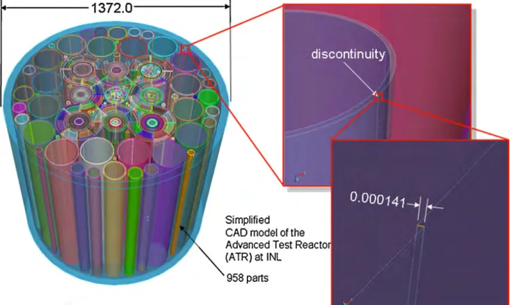
Figure 2 shows just one example of small undesirable features that tend to show up regularly in CAD models. The main diagram to the left is a simplified CAD model of the core of the Advanced Test Reactor (ATR) at Idaho National Laboratory. The model was simplified by both the use of significant defeaturing of small parts and components, and axial variation in the model is ignored. Further, much of the assembly detail and the geometry of the fuel plates in the serpentine fuel have been homogenized away. A sequence of magnified insets are shown to the right of the model, illustrating the presence of a sliver surface in the CAD data description. The sliver surface can be the result of sloppy modeling practices, but can also be the result of variation in the way geometric tolerances are defined in different solid modeling tools. The translation procedures can often fill gaps in the model by inserting sliver surfaces such as the one shown in Figure 1. Most meshing algorithms such as advancing front and Delaunay methods use the CAD data description as the initial input for the algorithm and assume that topology within the CAD description must be preserved in the mesh. Without discovering and resolving the sliver surface shown in this figure, elements that are on the order of 1×10⁻⁴ times smaller in this region than in the rest of the model would result, with the consequence of poor mesh quality or a failed mesh.
Figure 1. Sliver surface in the ATR CAD model due to a tolerance issue in the solid model translation.
not only address design concerns but also take into account meshing and analysis issues should be considered. Because CAD translation can be a major culprit in this bottleneck, standards that address tolerance issues would benefit modeling and simulation tremendously. These solutions are primarily programmatic in nature and should be addressed from an organizational or community standpoint.
Owen (2007) and Clark (2007) describe the capability to automatically diagnose potential geometry problems that will effect meshing and provide solutions in an automated or fully automatic manner. This will ultimately lead to tools that are tolerant of flaws in the CAD data representation, reducing the amount of manual adjustment that is currently required. Another approach would be the establishment of a CAD-based framework that is customized for reactor core modeling. This tool could incorporate a library of stock geometry configurations typical for reactor modeling that could be customized for particular configurations and experiments. The ability to maintain the geometry from its inception would eliminate the need for geometry translation, reducing the necessity for complex diagnostics and geometry clean-up operations.
5
MESHING TOOLS
A variety of tools have been developed in industry to address the complex requirements of mesh generation for multiphysics applications. Examples include the COMSOL® analysis package (http://comsol.com), ABAQUS/SIMULIA® (http://www.simulia.com), ANSYS/ICEM® (http://www.ansys.com) and CFD-CADalyzer® (http://www.cfdrc.com). While recognizing the tremendous advances that have been made in mesh generation technology over the past decade or more, reactor simulation imposes new requirements that may be difficult or impossible to resolve with existing tools.
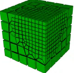
Figure 2. All-hexahedral mesh of the Idaho National Laboratory Advanced Test Reactor (ATR) using the CUBIT (2009) Geometry and Meshing Toolkit developed by Sandia National Laboratories.
5.1 Mesh Generation Methods
1998) or multi-sweeping (White, 2004) technologies have proven themselves very useful for “sweepable” geometry such as the ATR in Figure 1.
The ability to automatically generate an all-hexahedral mesh for arbitrary geometry configurations remains a significant research objective. Staten’s (2006) Unconstrained Plastering technology, as well as octree-based methods that incorporate sheet insertion techniques such as those introduced by Shepherd (2007), are promising technologies that will continue to be explored. Unconstrained Plastering, shown in Figure 3, is an advancing front method that begins from the geometry boundary and forms layers of hexes as it advances towards the interior. This procedure produces very high quality elements throughout without the need for manual decomposition, however it is still under development. Sheet insertion techniques, shown in Figure 4, start with a base mesh; in this case a Cartesian grid. Surfaces are captured from the grid by inserting layers of hexahedra near the boundary and smoothing the nodes to improve element quality. This method, while frequently used for meshing models with no topology (no sharp edges), is being extended for the more complex geometry encountered in reactor core modelling.
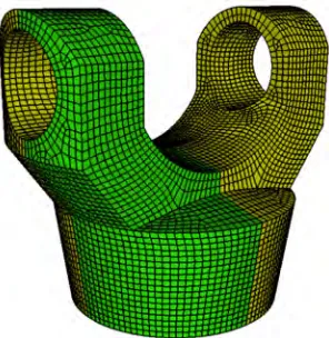
Figure 3. A fully unstructured hexahedral mesh of a mechanical part meshed using Unconstrained Plastering. (Figure courtesy of M. L. Staten)
Figure 4. Hexahedral mesh of a portion of
mechanical part meshed using a grid based scheme with surfaces captured using sheet insertion.
Unfortunately, “unsweepable” geometry is very common in a nuclear reactor. One example of this is the wire wrapped pins in a fast reactor shown in Figure 5. Other examples include the support and control structures above and below the core geometry in the upper and lower plena.
Figure 5. The wire wrapped pins of a 19-pin fast reactor model. Note how the wires spiral the same direction on each pin to keep them from touching. While still simple in nature, the wire spiral makes it impossible to sweep the mesh end to end.
5.2 Multi-Physics Considerations
required throughout the entire domain. These different physical models impose distinct requirements on the mesh. Fluids modeling, for example, typically employs a highly anisotropic mesh to capture boundary layer flow and heat flux, while a coarse mesh is needed for neutronics in the coolant channels. Generating a single mesh that satisfies all constitutive models may not be possible due to these differing requirements of the underlying models. Currently, solutions to reactor multi-physics problem require the generation of independent meshes that individually satisfy the requirements of the physics and then use data transfer methods to transfer results between the meshes. For example, Jiao (2004) describes a promising method for data transfer between meshes called common refinement, and compares several data transfer operators. Data transfer methods may or may not be conservative and can affect solution accuracy.
As an example of some of the issues that can arise in the use of multiple meshes in a coupled multiphysics problem, consider the Brusselator problem where solutions for T and C are hosted on separate meshes,
where a ≤ x ≤ b, T(a, t) = T(b, t) = α, C(a, t) = C(b, t) = α / β, α = 0.6, β = 2.0, and D1 = D2= 0.025. The
Brusselator system was proposed by Prigogine and Lefever (1968) to model a chemical reaction diffusion system. Figure 6 shows a solution of the Brusselator system that employs the initial conditions T(x, 0) = f(x), C(x, 0) = g(x), where
and a = 15.
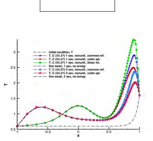
Figure 6.
T at time = 1 sec and 3 sec using cubic spline, common refinement and linear
interpolation on nonuniform meshes of (54, 37) nodes compared to the fine mesh reference solution
and the initial condition (linear interpolation results at time = 3 sec are not shown due to instability).
This example begins by the generation of meshes for each of the problems, T and C. To generate the mesh for T, an extremely fine mesh is generated for C and an initial coarse mesh is used for T. Then, the mesh for T is refined using an error metric devised to capture the curvature of the solution. Refinement continues until the solution on this mesh is within the asymptotic region. The mesh for C is then generated similarly. Both meshes are nonuniform as the curvature of the solution varies in space; the T mesh has 54 nodes and the C
between the meshes. Figure 6 shows the results for the T problem using different data transfer operators described in Jiao (2004) at 1 and 3 seconds of elapsed time. The black dotted lines show reference solutions where the T and C meshes are identical and very fine. Note the significant error between the reference solution and linear interpolation at 1 second (linear interpolation results were unstable at 3 seconds thus were not shown). Also note the excellent performance of a cubic spline transfer operator on this problem. In summary, this example shows that resolving the spatial length scales of each of the physics equations is necessary but not sufficient to resolve the spatial scales of the coupled multiphysics problem if the spatial features occur in different locations of the domain. Further, it shows that the data transfer operator has an impact on the solution accuracy and stability if this is the case.
Clearly, multiphysics calculations hosted on multiple meshes also require the generation of multiple meshes and a multiplication of the meshing expense involved with complex geometry. There may be an alternative to this approach that still allows supporting unique requirements of each physical model. We propose a common base mesh, known as a net (Hansen, 2008), in which goal-based adaptation is employed to satisfy the requirements of geometric fidelity and the physical models. In this scenario, a coarse base mesh is generated that spans the entire reactor domain. This mesh is automatically refined to meet the needs of the thermal-hydraulics computation, and then automatically refined in a different manner to meet the needs of the neutronics calculation, allowing multiple physics solutions to be hosted on the same base mesh definition. Use of a net may mitigate many of the issues that arise in the multiple mesh concept.
Figure 7. Example of net (master mesh) shown in (A). Meshes (B), (C), and (D) are created by refining the net in different ways to meet the requirements of the underlying physics computed on each. The union of all the meshes (union mesh) is shown in (E) (reprinted from Solin et. al. (2009) with permission).
Solin et. al. (2009) present an excellent study on the use of the concept of a net for a coupled thermoelastic problem. This approach begins by defining the net (called a master meshτm by Solin), shown in Figure 7(A). Diagrams (B), (C), and (D) depict different meshes, each derived from the element(s) of the base net. Each of these diagrams represents a mesh that supports a calculation that requires spatial refinement in a different location than the others. In the case of (B), refinement at the lower-left corner is needed to resolve the solution hosted by it, perhaps (C) is supporting a boundary layer solution along the left edge of the master element, and (D) captures a boundary layer at the upper edge. An important principle of a net is that it serves as the common basis of refinement; it is sufficiently coarse that all the underlying meshes supporting the calculation may be derived from it.
Figure 8. Qk is a virtual element on the union mesh. The shaded region shows the shadow of the virtual element on meshes (B), (C), and (D) (reprinted from Solin et. al. (2009) with permission).
adaptation in the physical model approximations and a consistent spatial integration scheme for the solution of the multiphysics problem.
Data transfer problems between adjacent domains with disparate physics can be handled by enforcing a conformal mesh at the mesh interface. Several techniques are either in development or have been developed to locally modify the mesh topology to ensure a conformal mesh. Figure 9 shows an example of a tet-hex interface developed by Owen (2001) where local tetrahedra topology operations are performed to match the quadrilateral interface. Pyramid shaped elements are introduced at the interface to maintain a conformal condition to avoid the hanging diagonal edge AB as shown in Figure 10.
Figure 9. Conforming mixed tet-hex mesh with pyramid elements at the interface between elements types. (Figure courtesy of Ansys Inc.)
Figure 10. Pyramid element provides a convenient transition between tet and hex element shapes.
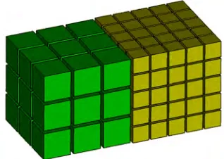
Another technique introduced by Staten (2009), known as Mesh Matching, takes two adjacent all-hexahedral meshes with different topology and resolution. By manipulating the local topology of all-hexahedral layers, a conformal condition can be automatically enforced. Figures 11 and 12 show a simple example of the capability. Local modifications to the hexahedra near the interface can be propagated into one or both volumes based on user preference.
Figure 11. Initial 2-domain mesh with non-conforming condition at its interface
Figure 12. Mesh following mesh matching procedure with conforming interface.
While most current multi-physics methods do not typically consider enforcing a conformal mesh across interface domains, this may be a viable option to reduce error often associated with other data transfer techniques.
5.3 Parallel Mesh Generation
issues that arise is the necessity to initially partition the geometry to balance the load between processors. As the simulation proceeds and mesh refinement and coarsening is locally applied, dynamic load partitioning is necessary. Codes must be designed to handle dynamic repartitioning and load balancing to manage this process.
Figure 13. 2D locally h-adapted grid with hanging nodes
Figure 14. 3D locally h-adapted grid without hanging nodes
6
SPATIAL ADAPTATION
The multi-scale and multi-physics nature of reactor simulation requires the ability to adaptively modify the mesh both temporally and spatially. h-adaptation, or the ability to cut elements into smaller pieces to better capture physics can be employed, but often requires significant changes in element sizes or introduction of hanging nodes, particularly for hexahedral or structured meshes. Figures 13 and 14 contrast the difference between h-adaptive grids with and without hanging nodes for 2D and 3D grids. Parrish (2007) recently generalized the ability to generate fully conformal (without hanging nodes) local refinement of hexahedral meshes. While in most cases, a conformal grid is preferred; one of the drawbacks has been its inability to perform the inverse operation of coarsening. Recent and on-going work by Shepherd et. al. (2009) has generalized this capability to permit automatic local and conforming quadrilateral and hexahedral coarsening. Figure 15 shows the result of selectively removing local layers or sheets of hexes to progressively reduce the resolution of the hexahedra in a particular region of the mesh. To be effective in practical adaptive analysis, the ability to conformally refine and coarsen as needed based upon an error metric or general sizing function will be required. Work is ongoing in this area.
Figure 15. Progressive conformal coarsening of a hexahedral mesh (Figure courtesy of A. Woodbury)
Figure 16. The left image shows an initial algebraic mesh on a corkscrew surface, to the right is the mesh improved with the Laplace–Beltrami Target Metric method.
One additional form of adaptation known as p-refinement may also be necessary to capture geometric curvatures or highly non-linear physics. In this case, the element order is locally increased based upon error or physical characteristics.
For adaptation to be successfully employed, it is necessary to develop a quality metric, or error indicator, that is representative of the quality of the solution. Further, this indicator must be combined with one of the above mesh refinement approaches to result in a robust, adaptive scheme. Even for single-physics applications, this is an area of active research. More issues will arise in extending this work to multi-physics simulations inside a reactor core.
Another aspect of mesh adaptation is the need to automatically incorporate geometric factors into the local mesh size. Mesh generation and refinement algorithms require a sizing function that will drive the element size throughout the model. A background scalar field that is a function of geometric curvature, feature size, feature thickness and proximity in addition to a local error indicator should be combined into a single function that can be quickly and easily queried during the initial mesh generation procedure or from any of the refinement operations described above. One example of this technology is proposed by Quadros et. al. (2004), where a background sizing function based upon an octree decomposition of the model, is generated as a function of geometric critera. Smaller function values are computed at regions of high curvature and thin sections, while larger values are computed in thick or blocky regions as illustrated in Figure 17. Further work is needed in this area so that both geometric sizing criteria and criteria from error indicators merge into a single sizing function. This would be combined such that the smaller value of geometric or error criteria would influence the local size while controlling for high gradients within the function.
Figure 17. Examples of mesh sizing control that uses geometric characteristics. This illustrates the use of surface curvature as sizing criteria with varying levels of weighting. (Figure courtesy of W.R. Quadros)
7
SOFTWARE
nuclear reactors must be able to use these tools in a robust, straightforward, and repeatable manner. Meshing tools should be easy to use, employ automation as much as possible, and provide a visual interface to drive these operations that require user interaction. While there are a number of meshing tools currently available, none of them should be expected to meet all of the needs of reactor simulation, as they were not designed to do so, although it is expected that existing technologies may be heavily leveraged. It should also be expected that tools employed for reactor core modelling will support parametric changes to the model so that the core geometry may be modified without significant remeshing.
In addition, the scientific community developing new computational tools for geometry and mesh generation should also be able to contribute to a common, well-defined tool suite using common interfaces. This will greatly facilitate the sharing of tools and technology among diverse groups. These tools may include the following:
(1) Code that performs implicit h, r and p adaption on existing meshes that are driven by sizing criteria that incorporate error, quality and/or geometric criteria.
(2) Routines to perform intermesh data transfer, or remapping between different resolutions of the same mesh
(3) A lightweight geometry library that can be used by both the initial meshing and simulation applications in a parallel environment.
(4) A collection of meshing functions, that support creation and remeshing of grids for a variety of element types, including hex, tet, quad and tri as well as mixed element meshes.
(5) A set of mesh objects, data structures and support functions including mesh quality libraries, mesh input/output libraries, as well as a mesh database for common storage of mesh objects.
Some current examples of teams working towards these objectives are the U.S. Department of Defense CREATE MAGIC program and Solin’s HERMES effort at the University of Nevada-Reno. With the purpose of supporting modelling and simulation for complex ship and air vehicles required by the U.S. Navy and Air Force, a common set of tools that leverage the CUBIT geometry and Meshing Toolkit (2009) are currently under development within the CREATE program. While it is clear that different criteria and specific meshing tools will be unique for their application, it is helpful to understand that this is not a unique undertaking, and that tools and technologies are being developed to address common needs. HERMES (HighEr-ordeR Modular finite Element System) is a library of adaptive FEM and hp-FEM solvers for multidimensional multiphysics applications. Working together with groups such as CREATE and HERMES can help to springboard the technology for reactor core modelling and simulation.
8
CONCLUSION
There is much we can learn from other disciplines in developing geometry and meshing tools for reactor simulation. It is important to use these technologies where appropriate, however new technologies must be developed to address specific demands of nuclear reactor design and safety. This overview presented a selection of some of the major challenges to be considered in both mesh generation activities and the design of new simulation capabilities that will employ these meshes. It is clear that the meshing and simulation communities need to jointly discuss and develop a plan for what specific meshing technology is needed for multi-physics reactor core simulation.
Acknowledgements. The submitted manuscript has been authored by a contractor of the U.S. Government
under Contract Nos. DEAC07-05ID14517 (INL/JOU-07-13524) and DEAC04-94AL85000. Accordingly, the U.S. Government retains a non-exclusive, royalty-free license to publish or reproduce the published form of this contribution, or allow others to do so, for U.S. Government purposes.
REFERENCES
Clark, B.W., 2007 Removing Small Features with Real CAD Operations. In: Proceedings 16th International Meshing Roundtable, October P. 183-198
CUBIT Geometry and Meshing Toolkit 2009, Sandia National Laboratories, http://cubit.sandia.gov
Fuentes, D. Littlefield, D., Oden, J.T., Pridhomme, S., 2006. Extensions of goal-oriented error estimation methods to simulations of highly-non linear response of shock-loaded elstic-reinforced structures. Comput. Methods Appl. Mech. Eng. 195 (July(37-40)), P. 4659-4680, John H. Argyris Memorial Isue. Part I.
Hansen G., Owen, S.J., 2008 Mesh Generation Technology for Nuclear Reactor Simulation; Barriers and Opportunities, Nucl Eng Des Vol. 238:10. P. 2590-2605
Hansen G., Zardecki A., 2007 Unstructured surface mesh adaption using the Laplace-Beltrami target metric approach. J. Comput. Phys. Vol. 225:1. P. 165-182
Hardwick, M., 2005. DART system analysis presentation to simulation sciences seminar. June.
Jiao X., Heath M.T., 2004 Common-refinement-based data transfer between non-matching meshes in multi-physics simulations. Int. J. Numer. Meth. Vol. 61:14. P. 2402-2427
Knupp, P.M., 1998 Next-Generation Sweep Tool: A Method For Generating All-Hex Meshes On Two-And-One-Half Dimensional Geometries, In: Proceedings, 7th International Meshing Roundtable, P. 505-513
Owen, S.J., Clark, B.W., Melander, D.J., Brewer, M., Shepherd, J.F., Merkley, K., Ernst, C., Morris, R., 2007. An Immersive Topology Environment for Meshing, In: Proceedings 16th International Meshing Roundtable, October P. 553-577
Owen, S.J., Saigal, S. 2001 Formation of Pyramid Elements for Hexahedra to Tetrahedra Transitions, Computer Methods in Applied Mechanics and Engineering, Vol. 190:34 P. 4505-4518
Parrish, M., Borden, M., Staten, M.L., Benzley, S.E., 2007 A Selective Approach to Conformal Refinement of Unstructured Hexahedral Finite Element Meshes, In: Proceedings 16th International meshing Roundtable, October P. 251-268
Pebay, P.P., Stephenson, M.B., Fortier, L.A., Owen, S.J., 2007 pCAMAL: An Embarrassingly Parallel Hex Mesh Generator, In: Proceedings 16th International Meshing Roundtable, October P. 269-286
Prigogine, I., and Lefever, R., 1968. Symmetry breaking instabilities in dissipative systems. II. J. Chem. Phys., Vol. 48 P.1695–1700
Quadros, W.R., Vyas V., Brewer, M., Owen, S.J., Shimada, K. 2004 A Computational Framework for Generating Sizing Function in Assembly Meshing, In: Proceedings 14th International Meshing Roundtable, Sept. P. 399-416
Shepherd, J.F., 2007 Topologic and Geometric Constraint-Based Hexahedral Mesh Generation, Dissertation, University of Utah
Shepherd, J.F., Dewey, M.W., Woodbury, A.C., Benzley, S.E., Staten, M.L., Owen, S.J., 2009 Adaptive Mesh Coarsening for Quadrilateral and Hexahedral Meshes. Finite Elements in Anal. and Des. (in press)
Solin, P., Cerveny, J., Dubcova, L., Andrs, D., 2009. Monolithic Discretization of Linear Thermoelasticity Problems via Adaptive Multimesh hp-FEM, J. Comput. Appl. Math (in press)
Staten M.L., Kerr R.A., Owen, S.J., Blacker, T.D., 2006 Unconstrained Paving and Plastering: Progress Update. Proceedings 15th Int. Meshing Roundtable. P. 469-486
Staten, M.L., 2009 Sheet-based Generation and Modification of Unstructured Conforming All-Hexahedral Finite Element Meshes, Dissertation, Carnegie Mellon University (in progress)
Thompson, J.F., 1996. A Reflection on Grid Generation in the 90s: Trends, Needs and Influences. In: Proceedings of the Fifth International Conference on Grid Generation in Computational Field Simulation. Mississippi State University, April, P. 1029-1110.