Comparative Viscous Flow Analysis for
Rocket Engine Convergent-Divergent Nozzle
for Distinct Geometric Parameters
Deepak Gaur1, Om Prakash2
Senior Research Assistant, DRDO Bhavan, DRDO, New Delhi, India1
Deputy Director, BF&A, DRDO Bhavan, DRDO, New Delhi, India2
ABSTRACT: A nozzle is a double-conical shaped tubular structure with varying cross-sectional area. It converts the pressure energy of the fluid flow into the kinetic energy. In a nozzle, especially de Laval or Convergent-Divergent (C-D) nozzle, the flow initially converges in the converging section of the nozzle to the throat area or minimum area, and then then expands through the divergent section of the nozzle. Because of high kinetic energy of the exhaust gases or flow in the exit region, the flow exits off the nozzle at a very high velocity, which in turn produces substantial thrust to propel the rocket. But during the energy conversion, i.e., from pressure energy to kinetic energy, some part of energy is lost. In order to achieve highest possible exit velocity and thus maximum thrust, loss should be minimized through optimization of nozzle shape and size. In this research, multi-divergent angle in divergent portion of the nozzle is taken in consideration for constant nozzle length and cross-sectional exit area. A computational fluid dynamics analysis has been carried out on such nozzle for multiple cases like single divergent angle, double divergent angle, and triple divergent angle. On comparison of the result it is observed that triple divergent angle in a nozzle produces maximum thrust.
KEYWORDS: Convergent-divergent nozzle, de Laval nozzle, converging section, diverging section
I. INTRODUCTION
Nozzle is a double-conical shaped tubular device that is used to convert pressure energy, of the chemical-thermal process, which is generated in the combustion chamber of the engine into kinetic energy. It converts the high temperature, high pressure, and low velocity gas from the combustion chamber into the high velocity gas of low temperature and pressure. The convergent-divergent nozzle, also known as the de Laval nozzle, has exhaust velocity ranging between 2 - 4.5 km/sec. The Mach number at the inlet of the nozzle is less than one. Through the convergent section the flow accelerates to the sonic velocities till the nozzle throat and then further accelerated to the supersonic velocities in the diverging section of the nozzle.
The research aims at increasing the thrust produced, through the use of multi-divergent angle within the rocket nozzle for a constant back pressure. As it is known for conventional C-D nozzle, the flow can be accelerated to higher velocities depending on the geometry of the nozzle, resulting in generation of optimal thrust. But, in order to increase thrust any further, existing nozzle geometry must be optimally modified by introducing multi-divergent angles within the design. In this research, multi-divergent angles are introduced in existing design with main objective of improving exit Mach number and thus increasing thrust. Results generated for multi-divergent angles are compared with that of the conventional design in order to determine improvement in thrust efficiency. The research proceeds with the design of conventional convergent-divergent nozzle which is single divergent angle nozzle. Conventional design is optimized for maximum thrust through introduction of multi-divergent angles i.e., 2 divergent angles, and 3 divergent angles, in latter half of the nozzle for fixed back pressure, length, and exit area of the nozzle.
and modelling, data obtained from reference [1] is taken as standard. Results are compared with the reference geometry taken from reference [1] to assure that newly generated single divergent angle nozzle geometry can be taken as a reference standard for this research. Further, through geometric modifications and grid refinement,simulationsare carried out for multi-divergent nozzle geometries in ANSYS FLUENT®software. For validation and analysis, simulated results are compared with that of the conventional design.
Paper is organized as follows. Section II describes generation of single divergent angle nozzle geometry based on reference [1] data, along with geometric modifications carried out to model multi-divergent angle nozzles. Section III presents simulations along with the results for variable divergent angle rocket nozzle geometries along comparison between modified geometries and conventional single divergent angle nozzle design. Finally, Section IV presents conclusion.
II. DESIGNANDMODELLING
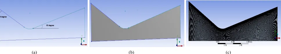
A 2D single divergent rocket nozzle model is created based on the geometric parameters from reference [1] using design modeler in ANSYS WORKBENCH®software. As in reference [1], most optimal single divergent angle for rocket nozzle is taken to be 15°for unstructured mesh design.Multiple drawing tools and constraints were used to make the sketch of the geometry.
Table 1. Reference Nozzle Dimensions and Boundary Conditions
Inlet width 1.000 m
Throat width 0.304 m
Exit width 0.861 m
Radius of curvature at throat 0.228 m
Convergent length 0.640 m
Convergent angle 30°
Divergent angle 15°
Total pressure 44.10 bar
Total temperature 3400 K
Mass flow rate 826.0 Kg/s
Based on the data from reference [1], a sketch is created based on which complete surface body is generated. Nozzle geometry is structurally meshed because of advantages like requirement of less computational geometry, higher degree of control, and alignment leading to better convergence.
Fig. 1. Design and Modelling (a) Single divergent angle rocket nozzle sketch (b) Single divergent angle rocket nozzle surface body (c) Single divergent angle rocket nozzle meshed geometry
Comparison with Reference Geometry
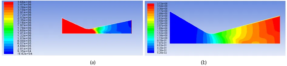
For the single divergent angle rocket nozzle geometry, the Mach number at the inlet of the nozzle is obtained to be 0.0554 M. The velocity of the flow increases while passing through the throat and thus, divergent section of the rocket nozzle. At the exit section of the nozzle, the velocity is observed to be 3.720M.On comparing Mach number value for modelled structured mesh geometry with the reference unstructured mesh geometry, difference observed at the exit section of the nozzle to be 3.87 %.
Fig. 2. Design and Modelling (a) Mach number contour for single divergent angle rocket nozzle geometry (b) Static pressure contour for single divergent angle rocket nozzle geometry
For the single divergent angle rocket nozzle geometry, the static pressure contour displayed decrement in the static pressure throughout the rocket nozzle. Where, static pressure at the inlet section of the nozzleis found to be1.651E+07 N/m2, the pressure value decreased to -9.221E+04 N/m2 at the exit section of the nozzle. On comparing static pressure value for modelled structured mesh geometry with the reference unstructured mesh geometry, difference observed at the exit section of the nozzle to be 1.06 %. Comparative results are presented in Table 2.
Table 2. Comparative Results
Parameters Reference rocket nozzle Modelled rocket nozzle
Mach no. at nozzle inlet 0.0577 0.0554
Mach no. at nozzle exit 3.864 3.720
Static pressure at nozzle inlet
1.713E+07 N/m2 1.651E+07 N/m2
Static pressure at nozzle exit
-9.320E+04 N/m2 -9.221E+04 N/m2
Since the difference between the reference and the modelled rocket nozzle values of parameters are considerably less, similar solution settings can be used for further research.
2 Divergent Angles Rocket Nozzle
The conventional modelled single divergent angle convergent-divergent rocket nozzle is modified through implementation of 2 divergent angles in the divergent section of the rocket nozzle while keeping length and exit area same as the original case. First 45% of the total divergent length is modified with divergent angle of 20.86°. Next 45% of the divergent length is modified with divergent angle of 10.84°, and the last 10% of the divergent length is modified with divergent angle of 0° in order to straighten the flow. Once sketch is completed, surface geometry is created which is structurally meshed at last.
Fig. 3. Design and Modelling (a) Sketch of 2 divergent angles nozzle
Fig. 3. Design and Modelling (a) Surface body of 2 divergent angles nozzle (b) Structured mesh geometry of 2 divergent angles nozzle
3 Divergent Angles Rocket Nozzle
The conventional modelled single divergent angle convergent-divergent rocket nozzle is modified through implementation of 3 divergent angles in the divergent section of the rocket nozzle while keeping length and exit area same as the original case. First 30% of the total divergent length is modified with divergent angle of 24°. Next 30% of the divergent length is modified with divergent angle of 16.71°, further 30% of the divergent length is modified with divergent angle of 7.94°, and the last 10% of the divergent length is modified with divergent angle of 0° in order to straighten the flow. Once sketch is completed, surface geometry is created which is structurally meshed at last.
Fig. 4. Design and Modelling (a) Sketch of 3 divergent angles nozzle (a)
(b) (c)
Fig. 4. Design and Modelling (b) Surface body of 3 divergent angles nozzle (c) Structured mesh geometry of 3 divergent angles nozzle
III.SIMULATIONANDANALYSIS
Single Divergent Angle Nozzle
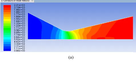
On simulating meshed geometry in ANSYS FLUENT® software, it is found that the axial velocity is increased from inlet to the exit portion of the rocket nozzle. An exit axial velocity of 2210 m/s is obtained at the exit portion of the rocket nozzle.
Fig. 5. Simulation and Analysis (a) Axial velocity contour
Mach number contour of the rocket nozzle showed increase in Mach number from inlet to exit portion of the nozzle as 0.0554 M to 3.72 M.
Fig. 5. Simulation and Analysis (b) Mach number contour (c) Mach no. Vs positionplot
However, static pressure contour showed a decline in the static pressure throughout the rocket nozzle. At the inlet, the static pressure is found to be 1.651E+07 N/m2 which reduces to -9.221E+04 N/m2 at the nozzle exit.
(b) (c)
(a)
Fig. 5. Simulation and Analysis (d) Static pressure contour (c) Static pressure Vs position plot
Resulting thrust for single divergent angle rocket nozzle is calculated to be 1712.78 kN.
2 Divergent Angles Nozzle
On simulating meshed geometry for 2divergent angles nozzle, it is found that the axial velocity is increased from inlet to the exit of the rocket nozzle. An exit axial velocity of 2350 m/s is obtained at the exit portion of the rocket nozzle.
Fig. 6. Simulation and Analysis (a) Axial velocity contour (b) Axial velocity Vs position plot
Mach number contour of the rocket nozzle showed increase in Mach number from inlet to exit portion of the nozzle as 0.0548 M to 4.58 M.
Fig. 6. Simulation and Analysis (c) Mach number contour (d) Mach no. Vs position plot
However, static pressure contour showed a decline in the static pressure throughout the rocket nozzle. At the inlet, the static pressure is found to be 1.532E+07 N/m2 which reduces to -5.251E+04 N/m2 at the nozzle exit.
(d) (e)
(a) (b)
Fig. 6. Simulation and Analysis (e) Static pressure contour (f) Static pressure Vs position plot
On comparing with the results for single divergent angle nozzle, increase in pressure drop at the exit of the nozzle section is observed. Also, increase in exit velocity and Mach number is noticed.
Resulting thrust for 2 divergent angles rocket nozzle is calculated to be 1845.52 kN.
3 Divergent Angles Nozzle
On simulating meshed geometry for 3 divergent angles nozzle, it is found that the axial velocity is increased from inlet to the outlet of the rocket nozzle. An exit axial velocity of 2390 m/s is obtained at the exit portion of the rocket nozzle.
Fig. 7. Simulation and Analysis (a) Axial velocity contour (b) Axial velocity Vs position plot
Mach number contour of the rocket nozzle showed increase in Mach number from inlet to exit portion of the nozzle as 0.0545 M to 5.02 M.
Fig. 7. Simulation and Analysis (c) Mach number contour (d) Mach no. Vs position
However, static pressure contour showed a decline in the static pressure throughout the rocket nozzle. At the inlet, the static pressure is found to be 1.662E+07 N/m2 which reduces to -4.941E+04 N/m2 at the nozzle exit.
(e) (f)
(a) (b)
Fig. 6. Simulation and Analysis (e) Static pressure contour (f) Static pressure Vs position plot
On comparing with the results for previous two geometries, maximum pressure drop at the exit of the nozzle section is observed for the 3 divergent angle nozzle. Also, maximum increase in exit velocity and Mach number is noticed.
Resulting thrust for 3 divergent angles rocket nozzle is calculated to be 1886.54 kN.
Table 3. Comparative Results
Divergent Angle(s) Exit Velocity Mach No. Exit Static Pressure Thrust
Single Divergent Angle 2210 m/s 3.72 -9.221E+004 N/m2 1712.78 kN
2 Divergent Angles 2350 m/s 4.58 -5.251E+04 N/m2 1845.52 kN
3 Divergent Angles 2390 m/s 5.02 -4.941E+04 N/m2 1886.54 kN
IV.RESULTS
The convergent-divergent nozzle tends to provide maximum thrust when optimized. The thrust can be further increased by application of multi-divergent angles. An increase of 7.75% in thrust is observed for the case of 2 divergent angles rocket nozzle, and an increase of 10.145% in thrust is observed for the case of 3 divergent angles rocket nozzle, on comparing with results for standard one divergent angle rocket nozzle.
REFERENCES
1. Biju Kuttan P, M Sajesh, “Optimization of Divergent Angle of a Rocket Engine Nozzle Using Computational Fluid Dynamics”, vol. 2, issue 2, pp. 196-207, 2013.
2. K.P.S.Surya Narayana, K.Sadhashiva Reddy, ”Simulation of Convergent Divergent Nozzle using CFD analysis”, vol. 13, issue 4, pp. 58-65, 2016.
3. P.Parthiban, M. Robert Sagayadoss, T. Ambikapathi, “Design and Analysis of Rocket Engine Nozzle bu using CFD and Optimization of Nozzle parameters”, International Journal of Engineering Research, vol. 3, issue 5, pp. 312-319, 2015.
4. K.M. Pandey, A.P. Singh, “CFD Analysis of Conical Nozzle for Mach 3 at Various Angles of Divergence with Fluent Software”, International Journal of Chemical Engineering and Applications, Vol. 1, No. 2, pp. 179-185, 2010.
5. Parashram V. Patil, Akshay A. More, Shubham M. Patil, Milind R. Mokal, “Optimization In DE-Laval Nozzle Design to Increase Thrust”, International Journal of Scientific & Engineering Research, Vol 8, issue 3, pp. 81-84, 2017.
6. Bogdan AlexandruBelega, TrungDucnguyen, “Analysis of flow in Convegent-Divergent Rocket Engine Nozzle using Computational Fluid Dynamics”, International Conference of Scientific Paper AFASES 2015, pp. 28-30, 2015.
7. Karna S. Patel,” Flow Analysis and Optimization of Supersonic Rocket Engine Nozzle at Various Divergent Angle using Computational Fluid Dynamics”, IOSR-JMCE, vol. 11, issue 6, pp. 01-10, 2014.
8. Lars Davidson, “An introduction to turbulence models”, Department of thermo and fluid dynamics, Chalmers University of technology, Gothenburg, Sweden, November, 2003.
9. H.K. Versteeg and W.MalalaSekhara, “An introduction to Computational Fluid Dynamics”, British Library cataloguing pub., 4th ed. 1996. 10. B.P. Madhu, S. Sameer, Kalyana Kumar M, M. Mani,G, “CFD Analysis of Convergent-Divergent and Contour Nozzle”, IJMET, vol. 8, issue
8, pp. 670-677, 2017.
11. C.A. Hunter, “Experimental, Theoretical, and Computational Investigation of Separated Nozzle Flows”, AIAA 98-3107. 12. Gaurav Sharma e.tal, “CFD Analysis of Rocket Nozzle”, University of Petroleum and Energy Studies, Dehradun, 2001.