University of Windsor
University of Windsor
Scholarship at UWindsor
Scholarship at UWindsor
Electronic Theses and Dissertations
Theses, Dissertations, and Major Papers
1-1-2007
Software profiling for an FPGA-based CPU core.
Software profiling for an FPGA-based CPU core.
Jason G. Tong
University of WindsorFollow this and additional works at: https://scholar.uwindsor.ca/etd
Recommended Citation
Recommended Citation
Tong, Jason G., "Software profiling for an FPGA-based CPU core." (2007). Electronic Theses and Dissertations. 6963.
https://scholar.uwindsor.ca/etd/6963
Softw are P rofilin g For A n F P G A -B a sed
C P U Core
by
J a so n G . T on g
A Thesis
Subm itted to the Faculty of G rad u ate Studies and Research
through Electrical and C om puter Engineering
in P a rtia l Fulfillment of the Requirem ents for the
Degree of M aster of Applied Science at the
U niversity of W indsor
Library and Archives Canada
Bibliotheque et Archives Canada
Published Heritage Branch
395 W ellington Street Ottawa ON K1A 0N4 Canada
Your file Votre reference ISBN: 978-0-494-34988-5 Our file Notre reference ISBN: 978-0-494-34988-5
Direction du
Patrimoine de I'edition
395, rue W ellington Ottawa ON K1A 0N4 Canada
NOTICE:
The author has granted a non
exclusive license allowing Library
and Archives Canada to reproduce,
publish, archive, preserve, conserve,
communicate to the public by
telecommunication or on the Internet,
loan, distribute and sell theses
worldwide, for commercial or non
commercial purposes, in microform,
paper, electronic and/or any other
formats.
AVIS:
L'auteur a accorde une licence non exclusive
permettant a la Bibliotheque et Archives
Canada de reproduire, publier, archiver,
sauvegarder, conserver, transmettre au public
par telecommunication ou par I'lnternet, preter,
distribuer et vendre des theses partout dans
le monde, a des fins commerciales ou autres,
sur support microforme, papier, electronique
et/ou autres formats.
The author retains copyright
ownership and moral rights in
this thesis. Neither the thesis
nor substantial extracts from it
may be printed or otherwise
reproduced without the author's
permission.
L'auteur conserve la propriete du droit d'auteur
et des droits moraux qui protege cette these.
Ni la these ni des extraits substantiels de
celle-ci ne doivent etre imprimes ou autrement
reproduits sans son autorisation.
In compliance with the Canadian
Privacy Act some supporting
forms may have been removed
from this thesis.
While these forms may be included
in the document page count,
their removal does not represent
Conformement a la loi canadienne
sur la protection de la vie privee,
quelques formulaires secondaires
ont ete enleves de cette these.
© 2007 Ja so n G. T ong
A b s tr a c t
A c k n o w le d g m e n ts
T h e day is finally here! I have successfully co m pleted one of m y life-tim e achievem ents, a M a s te r’s D egree in E lectrical an d C o m p u te r E ngineering. T h e re are several people who I w ould like to acknow ledge in th is d issertatio n .
F irs t an d forem ost, I w ould like to give m y sincerest th a n k s to m y supervisor, P rofessor M oham m ed A. S. K halid. I am in d e b te d for his invaluable advice, en courag em en t, m o ral su p p o rt an d g u idance th ro u g h o u t m y M a s te r’s research. His professionalism , know ledge an d ex p e rtise will never be forg o tten . I will alw ays value our research discussions t h a t we h a d over th e last few years. N ext, I would like to th a n k m y thesis co m m ittee m em bers: P rofessors N a ray an K a r an d N ader Z am ani, for th e ir invaluable suggestions, an d s u p p o rt th ro u g h o u t th is p ro je c t. S pecial th a n k s to P rofessor H u a p en g W u for his valuable tim e chairing th e M .A .Sc. Defence. Also, I w ould like to give a very special th a n k you to Lesley S h an n o n a n d B lair F o rt from U niversity of T oro n to for th e ir invaluable advice, tim e an d assistan ce in th is p ro je c t.
A C K N O W L E D G M E N T S
K evin Bisw as, H a rb A b d u l-H a m id , M a tth e w M eloche, A shkan H osseinzadeh N am in, M itra M irhassani, M ah zad A zarm eh r, Ali B id ab ad i, Josh D aniel a n d N a ta lia Salgo for th e ir friendship an d su p p o rt d u rin g m y stay.
M y h e a rtfe lt th a n k s go o u t to L isa P rice, for h e r editing skills a n d g re a t p atien c e in revising a m a jo rity of m y p a p e rs over th e years, including th is thesis. Also for her con tin u in g friendship a n d su p p o rt she h as given to me.
To R alene M arcoccia, th e A lte ra U niversity P ro g ra m , a n d th e A lte ra C o rp o ra tio n , I th a n k you for providing th e Nios II D evelopm ent F P G A b o ard s a n d th e full licenses for th e developm ent softw are.
F in a lly an d m o st im p o rta n tly , I am in d e b te d to m y p a re n ts Y im a n d M ay T ong for th e ir everlasting love, u n d e rsta n d in g a n d m o ral su p p o rt th ro u g h o u t m y M a s te r’s journey. T h is voyage w ould n o t have been easy to em bark on w ith o u t them .
C o n ten ts
A b str a c t iv
D e d ic a tio n v
A c k n o w le d g m e n ts v i
L ist o f F ig u r e s x ii
L ist o f T a b les x iii
L ist o f A b b r e v ia tio n s x iv
1 I n tr o d u c tio n 1
1.1 P rofiling Tools for
F P G A -B a se d E m b ed d ed S y s t e m s ... 1
1.2 T hesis O b j e c t i v e s ... 3
1.3 T hesis O rg a n iz a tio n ... 5
2 D e s ig n M e th o d o lo g ie s for E m b e d d e d S y s te m s 6 2.1 T ra d itio n a l D esign M e th o d o lo g y ... 7
2.2 H ardw are-S oftw are C o-D esign M ethodology ... 9
2.3 F u n c tio n -A rc h ite c tu re C o-D esign ... 11
C O N T E N T S
2.5 S u m m ary ... 16
3 P r o filin g T ools 17 3.1 P rofiling Tools an d th e Softw are P rofiling M e t h o d o l o g y ... 17
3.2 Softw are B ased P rofiling (S B P) T o o l s ... 20
3.2.1 In stru c tio n S et S im u la to r ... 21
3.2.2 G N U ’s g p r o f ... 22
3.2.3 In te l’s V T u n e ... 23
3.2.4 S u m m a ry of S B P T o o l s ... 24
3.3 Softw are B ased M em ory Profilers ( S B M P ) ... 24
3.3.1 V a l g r i n d ... 25
3.3.2 R a tio n a l S oftw are’s P u r i f y ... 26
3.3.3 S u m m ary of S B M P Tools... ... 27
3.4 H ard w are-C o u n ter B ased Profiling (H C B P ) T o o l s ... 27
3.4.1 H ard w are C o u n ters A p p r o a c h ... 28
3.4.2 P age M ig ratio n A p p r o a c h ... 29
3.4.3 D esktop P ro cesso r P rofiling C o u n t e r s ... 29
3.4.4 S u m m a ry of H C B P Tools... ... 30
3.5 F P G A -B a se d P rofiling (F P G A -B P ) T o o l s ... 31
3.5.1 S noopP ... 32
3.5.2 F req u en t L oop A nalysis T ool ( F L A T ) ... 33
3.5.3 W o O D S T o C K ... 34
3.6 Q u a lita tiv e C om parison of Profiling Tools ... 35
C O N T E N T S
4.2 A irw olf Profiling C o u n t e r ... 41
4.3 A irw olf’s Softw are D r i v e r s ... 42
4.4 S u m m a ry ... 44
5 E x p e r im e n ta l R e s u lts 45 5.1 T h e Nios II P rofiling E n v ir o n m e n t... 45
5.2 F P G A D evelopm ent B o ard a n d D esign C A D Tools ... 47
5.3 Profiling Tools S e t t i n g ... 48
5.4 Profiling S oftw are B e n c h m a r k s ... 49
5.5 C om parison of P rofiled R esu lts ... 51
5.5.1 D i j k s t r a ... 51
5.5.2 F ib o _ M a trix _ M u lt... 52
5.5.3 G am e of Life ... 53
5.5.4 B itC o u n t ... 55
5.5.5 D h r y s t o n e ... 56
5.5.6 S u m m a r y ... 57
5.6 P erfo rm an ce O verhead A n a l y s i s ... 58
5.6.1 D i j k s t r a ... 58
5.6.2 F ib o _ M a trix _ M u lt... 59
5.6.3 G am e of Life ... 60
5.6.4 B itC o u n t ... 60
5.6.5 D h r y s t o n e ... 61
5.6.6 S u m m a r y ... 63
6 C o n c lu sio n s an d F u tu re W ork 64 6.1 R esearch C o n tr ib u tio n s ... 65
6.2 F u tu re W o r k ... 66
V IT A A U C T O R IS
C O N T E N T S
List o f Figures
2.1 T h e T ra d itio n a l D esign M e th o d o lo g y ... 8
2.2 T h e H ardw are-S oftw are C o-D esign M e th o d o lo g y ... 10
2.3 T h e F u n c tio n -A rc h ite c tu re C o-D esign M e t h o d o l o g y ... 12
2.4 D esign Space E x p lo ra tio n ... 14
2.5 P la tfo rm B ased D e s i g n ... 15
3.1 S oftw are P rofiling M e t h o d o l o g y ... 19
3.2 P rofiling Tool C l a s s i f i c a t i o n ... 21
3.3 R a tio n a l P u rify ’s M em ory Profiling C olour C o d e ... 26
3.4 P ag e M ig ratio n A p p ro ach ... 30
3.5 S n o o p y ’s Profiling A rc h ite c tu re ... 32
3.6 S n o o p y ’s Profiling C o u n t e r ... 33
3.7 F req u e n t L oop A nalysis T o o l ... 34
3.8 W atc h in g O ver D a ta S tream in g on C o m p u tin g E lem ent Links . . . . 35
4.1 T h e A irw olf P rofiler ... 40
4.2 T h e A irw olf Profiling C o u n t e r ... 41
4.3 A n E xam p le of A irw olf’s S oftw are D r i v e r s ... 43
List o f Tables
3.1 C om parison of P rofiling T o o l s ... 37
5.1 Nios D evelopm ent B o ard C o m p o n en ts ... 46
5.2 B en ch m ark D e s c r i p t i o n s ... 50
5.3 P rofiled R esu lts for D i j k s t r a ... 51
5.4 P rofiled R esults for F ibo_M atrix_M ult ... 52
5.5 P rofiled R esu lts for G am e for Life using N ios2-gprof ... 53
5.6 P rofiled R esu lts for G am e for Life using A i r w o l f... 54
5.7 P rofiled R esu lts for B itC o u n t using N i o s 2 - g p r o f... 54
5.8 P rofiled R esu lts for B itC o u n t using A ir w o lf ... 55
5.9 P rofiled R esu lts for D h r y s t o n e ... 57
5.10 P erfo rm an ce O v erh ead A nalysis for D i j k s t r a ... 59
5.11 P erfo rm an ce O verhead A nalysis for F ib o .M a trix _ M u lt... 59
5.12 P erfo rm an ce O verhead A nalysis for G am e of Life ... 60
5.13 P erfo rm an ce O verhead A nalysis for B itC o u n t ... 61
L ist o f Abbreviations
A b b re v iatio n D efinition
AIB A valon Interface B us AM D A dvanced M icro D evices
A P I A dvanced P ro g ra m m in g Interface A SIC A p p licatio n Specific In te g ra te d C ircuit CAD C o m p u te r A ided D esign
C E C o u n ter E n able
C P E C o m p u tin g P ro cesso r E lem ent C P U C e n tra l P rocessing U nit
D$ D a ta C ache
D S P D ig ital Signal P rocessing
D T L B D a ta T ra n sla tio n Lookaside Buffer F C N F u n ctio n
F L A T F req u en t L oop A nalysis Tool F L C F req u en t Loop C ache
F P G A F ield P ro g ra m m a b le G a te A rray
F P G A -B P F ield P ro g ra m m a b le G a te A rray-B ased P rofiling FSL F ast S im plex Link
H C B P H ard w are-C o u n ter B ased P rofiling H C E L H its C o u n ter E n ab le Line
H D L H ard w are D escrip tio n L anguage 1$ In stru c tio n C ache
IC In te g ra te d C ircu it
ID E In te g ra te d D evelopm ent E nviro n m en t IP In tellec tu a l P ro p e rty
L IS T OF A B B R E V IA T IO N S
ISS In s tru c tio n Set S im u lato r LSW L ea st Significant W ord M S W M ost Significant W ord
N io s-II-P E Nios II Profiling E n v iro n m en t
P A P I P erfo rm an ce A dvanced P ro g ra m m in g Interface P B D P la tfo rm B ased D esign
P C P ro g ra m C o u n ter
P M A P ag e M ig ratio n A p p ro ach R A M R a n d o m Access M em ory SBB S h o rt B ackw ards B ranch
SB M P S oftw are-B ased M em ory P rofiling S B P S oftw are-B ased P rofiling
S O F S ta tic -R A M O b je c t File
S O P C S y stem O n P ro g ra m m a b le C hip S O T S am pling O ver T im e
S P M Softw are P rofiling M ethodology T C E T im e C o u n ter E n able
T C E L T im e C o u n te r E n ab le Line
U A R T U niversal A synchronous Receiver T ra n sm itte r
C h a p ter 1
I n tro d u c tio n
1.1
P rofilin g T ools for
F P G A -B a se d E m b ed d ed S y stem s
In recent years, em bedded system s have grow n in p o p u la rity due to th e ir increased processing power. T h ey are prev alen t in o u r m o d ern society, w here th ese system s are used in a w ide v ariety of ap p lica tio n s ran g in g from th e p erform ance of sim ple everyday task s to p ro d u c t m an u fa ctu rin g . C om m only used em bedded system s include cell phones, electronic pagers, television rem ote controls, d ig ita l cam eras, p erso n al d a ta assistan ts, DVD players, H D T V a n d m uch m ore. In large in d u stria l com panies, em bedded system s are used as p ro g ram m a b le controllers for m an u fa ctu rin g , nuclear
p o w e r g e n e r a t i o n , t r a n s p o r t a t i o n a n d m e d ic a l i n s t r u m e n t a t i o n .
in-1. IN T R O D U C T IO N
p u t / o u tp u t interfaces. 99% of th e c u rre n t m icroprocessors p ro d u c ed are used for em bedded system s ap p lica tio n s [67]. T h e p u rp o se of these system s is to ex ecu te softw are ap p lica tio n code t h a t is sto re d in m em ory. D ue to th e lim ita tio n s in th e h ard w are resources of th ese system s, th e y c a n n o t be as flexible an d re p ro g ra m m a b le as a d esk to p co m p u ter. D esk to p co m p u ters are gen eral-p u rp o se co m p u ters c o n tain in g various h ard w are co m p o n en ts which ca n b e p ro g ram m ed to im plem ent any ap p lica tio n or function. E m b ed d ed system s have d ed ica ted an d lim ited h a rd w a re resources th a t are designed specifically for p erfo rm in g th e ta sk s th a t are specific to a p a rtic u la r application.
T h e continuing adv an cem en t an d inn o v atio n of em bedded system s, re su ltin g in increased com plexity, h as led designers to significantly intensify th e ir developm ent efforts d u rin g th e design process. In ad d itio n to th e add ed difficulty, consum er de m a n d for th ese devices continues to rise, w hich has helped to sh o rte n design cycles an d tig h te n tim e -to -m a rk deadlines. T h e design of em bedded system s is becom ing significantly difficult w ith o u t th e use of c o m p u ter-aid ed design (C A D ) tools th a t can effectively p a rtitio n th e co m ponents into th e h ard w are or softw are dom ains. T h e re are o th e r ad d ed c o n stra in ts t h a t designers m u st consider, such as th e re d u c tio n of In te g ra te d C ircu it (IC ) chip a re a a n d system pow er co n su m p tio n while su stain in g m axim um perfo rm an ce [70].
1. IN T R O D U C T IO N
te rm in e w hich co m p o n en ts are th e p erfo rm an c e b o ttlen eck s an d w hich co m p o n en ts m eet th e tim in g requirem ents.
P rofiling tools are C A D to o ls t h a t m easu re th e perfo rm an ce of a softw are or h a r d ware sy stem based on th e tim e needed to p erfo rm c e rta in functions. T h e y also help in d e te c tin g problem s such as co m m u n icatio n b o ttlen eck s in a system , cache m isses an d o th e r im p o rta n t m easu rab le p erfo rm an ce m etrics. T h ey allow early d e te c tio n of perfo rm an ce b o ttle n eck s a n d help th e em b ed d ed system designers to optim ize th e ir designs in o rd e r to m eet sy stem p erfo rm an c e co n stra in ts [60, 51].
T h ere are several profiling to o ls available to d a y t h a t can be used to profile softw are code ru n n in g on a ta rg e t processor. T hese to o ls provide different profiling in fo rm a tio n t h a t can b enefit em bedded designers so t h a t th e y can o ptim ize th e softw are code. D espite th e v ariety of profiling tools t h a t are available, m an y of th e m use different m easuring techniques t h a t can p o te n tia lly provide in a c c u ra te feedback. T h e m a jo rity of th e profiling to o ls used are softw are-based, w hich require th e designer to com pile th e ir softw are p ro g ram s to include in stru m e n ta tio n code a t th e b in a ry level. T h is is n o t desirable since it is very intrusive to th e o riginal p ro g ram a n d can cause u n p re d ictab le execution b eh av io u r of th e softw are. S am pling techniques are also used in a v arie ty of profiling tools an d can provide varying resu lts d ep en d in g on th e sam pling frequency of th e profiler. T his consequently affects th e accu racy of th e profiled results, w hich can p o te n tia lly lead em b ed d ed designers to im plem ent th e w rong soft w are fu n c tio n s in hardw are. It is im p e ra tiv e t h a t profiling to o ls m inim ally d istu rb th e o riginal p ro g ra m b in a ry file an d have th e ab ility to provide a c c u ra te re su lts in order to c re a te an effective h ardw are-softw are p a rtitio n of th e em bedded system .
1.2
T h esis O b jectives
1. IN T R O D U C T IO N
1. To c reate a m in im ally intrusive profiler t h a t does n o t req u ire th e in se rtio n of in s tru m e n ta tio n code ad d ed to a softw are p ro g ra m ’s b in a ry file. T h is profiler should b e able to a c cu ra te ly m easure th e a m o u n t of tim e a softw are fu n c tio n has ta k e n to execute on a ta rg e t processor.
2. Use th e developed profiler to profile several com m on softw are b en c h m a rk s ru n ning on an F P G A -b a se d soft-core processor system .
To satisfy th e first objective, an F ield P ro g ra m m ab le G a te A rray (F P G A )-b a se d on-chip profiler, called th e A irw o lf profiler, was developed. T h is profiler co n tain s tw enty profiling coun ters t h a t can m easure th e perfo rm an ce of u p to tw en ty different softw are functions. It is m inim ally intrusive an d collects profiling in fo rm atio n by m easuring th e n u m b er of system clock ticks t h a t each softw are function tak es to execute on a soft-core processor. For th e second objective, a profiling en vironm ent was developed t h a t is based on th e A lte ra Nios II soft-core processor [32]. T his en vironm ent was used to execute several softw are ben ch m ark s an d to profile th e m using th e A irw o lf profiler. T h e re su lts o b ta in e d using th e A ir w o lf profiler were com p ared a g a in st th o se o b ta in e d from th e G N U ’s g p ro f [36] softw are-based profiler. T h e resu lts collected using th e A irw o lf profiler show a significant increase in profiling accu racy over tho se of th e g p ro f profiler.
1. IN T R O D U C T IO N
1.3
T h esis O rganization
C h a p ter 2
D e s ig n M eth odologies f o r
E m bedded S y s te m s
T h e developm ent of em bedded system s involves th e co m b in atio n of h ard w are a n d so ft w are co m p o n en ts to g e th e r to m eet th e requ irem en ts of a specific ap p licatio n . T h ere are several design m ethodologies t h a t can help em bedded designers to co o rd in a te dif ferent design ta sk s in ord er to m eet tig h t tim e -to -m a rk e t deadlines an d to fulfill all th e specified p erfo rm an c e requirem ents. T hese are:
• T ra d itio n a l D esign M ethodology
• H ardw are-S oftw are C o-D esign
• F u n c t i o n a l A r c h i t e c t u r e C o -D e s ig n
2. D E S IG N M E T H O D O L O G IE S F O R E M B E D D E D S Y S T E M S
In th is c h a p te r a b rief in tro d u c tio n to these m ethodologies is pro v id ed so t h a t th e re ad er is able to u n d e rsta n d th e different ap p ro ach es th a t are used in th e design of em bedded system s.
2.1
T raditional D esig n M eth o d o lo g y
T h e T ra d itio n a l Design M ethodology [39] is a set of design appro ach es t h a t are com m only used in th e au to m o tiv e in d u stry [54]. T h is ap p ro ach usually follows a w aterfall m odel of system developm ent [69],
F igure 2.1 shows a flow chart for th e tra d itio n a l m ethodology for th e design of em bedded system s. In itia lly a set of specifications are defined w hich describe th e sy ste m ’s o p eratio n s an d th e perfo rm an ce re q u irem en ts th a t th e sy stem m u st satisfy. A fter th is in itia l step , th e h ard w are an d softw are co m ponents are designed in d ep en dently. U sually a g roup of h ard w are a n d softw are engineers develop th ese com p o n en ts d is ta n t from each o th e r an d a t different tim es d u rin g th e design process. T h e re is very m inim al in te ra c tio n betw een th ese groups as th e h ard w are a rc h ite c tu re is being built an d th e softw are code is w ritte n . It is usually p resu m ed th a t th ese com p o n en ts can be com bined to g e th e r w ith o u t an y in co m p atib ility issues. As th e com p o n en ts are fully synthesized an d functional, th e sy ste m s’ co m p o n en ts are in te g ra te d to g e th e r, d u rin g w h a t is know n as th e system in te g ra tio n stage. Following th is stag e is th e verification a n d p ro to ty p in g stage, d u rin g w hich designers verify an d te s t th e p ro to ty p e . Lastly, th e design is sent for fabricatio n .
T h is design m eth o d o lo g y is su ita b le for sm aller a n d sim pler designs, b u t is n o t feasible for com plex em bedded system s. It in tro d u ces m any problem s a n d causes
2. D E S IG N M E T H O D O L O G IE S F O R E M B E D D E D S Y S T E M S
System
Verfication
Fabrication
System
Specification
System
Integration
v .
Hardware
Components
Hardware
Synthesis
Hardware
Model
S '
Software
Components
Code
Generation
Software
Model
2. D E S IG N M E T H O D O L O G IE S F O R E M B E D D E D S Y S T E M S
com ponents, w hich were b u ilt in a different design tim e-fram e, rely on an u n su p p o rte d h ard w are fu n ctio n (or a rc h ite c tu re ) in ord er to execute properly. U sing th e tra d itio n a l design m ethodology, designers use m ost of th e ir tim e on in terface debugging ta sk s an d have less tim e for o th e r im p o rta n t ta sk s such as overall system verification, te stin g an d o p tim iza tio n . In som e cases, m any design ite ra tio n s m ay be re q u ired to m eet design goals an d c o n stra in ts. T h is m ay lead to m issed tim e -to -m a rk e t deadlines an d design obsolescence.
2.2
H ardw are-Softw are C o-D esig n M eth o d o lo g y
T h e C o-D esign m eth o d o lo g y for em bedded system s enables th e h ard w are a n d softw are com ponents to be designed concurrently. I t allows designers to find an efficient and balan ced hardw are-softw are p a rtitio n of th e com ponents of th e em bedded system , while m a in ta in in g com p atib ility . T h is m eth o d o lo g y ensures th e h a rd w a re p latfo rm is able to execute th e softw are com p o n en ts (or su p p o rtin g ap p lica tio n softw are) an d has th e necessary c o m p u tin g resources for p ro p e r execution.
O ne of th e m ain ad v a n ta g es of th e co-design m ethodology is th e a b ility to d etec t early co m p atib ility issues in th e design. W h e n problem s are d e te c te d earlier in th e design stage, th e y are easier an d less expensive to fix [55].
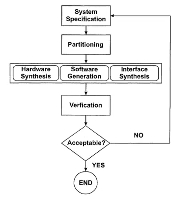
T h e re are m any p ro p o sed co-design m ethodologies an d th e m a jo rity of th e m have focused on th e im p le m e n ta tio n of d ig ita l signal processing a lg o rith m s or em bedded system s design [25]. In each of th e m ethodologies, m ost have com m on design stages th a t will eventually lead to a system t h a t perform s a specific fu n ctio n or ap p licatio n . A flow chart for th e hardw are-softw are co-design m ethodology is show n in F ig u re 2.2 [30].
2. D E S IG N M E T H O D O L O G IE S F O R E M B E D D E D S Y S T E M S
NO
Acceptable?
YES
END
Partitioning
System
Specification
Verfication
Hardware
Synthesis
Software
Generation
Interface
Synthesis
2. D E S IG N M E T H O D O L O G IE S F O R E M B E D D E D S Y S T E M S
hardw are-softw are p a rtitio n in g stag e d eterm in es w hich functions o r co m p o n en ts are to be placed in th e h ard w are d o m ain a n d w hich are h an d led by softw are. T h e th ird a n d m o st im p o rta n t sta g e is synthesis, in w hich th e hardw are, softw are an d interface c o m p o n en ts are synthesized concurrently. H ard w are an d softw are engineers co n tin u ously in te ra c t w ith each o th e r by exchanging perfo rm an ce in fo rm a tio n a n d fu n ctio n al re q u irem en ts of all th e com ponents. T h is ensures t h a t th e h ard w are a rc h ite c tu re an d th e softw are p ro g ram can execute to g e th e r w ith o u t difficulty. F inally, th e verification stag e determ in es if th e designed sy stem m eets th e design req u irem en ts an d p erfo r m ance co n stra in ts. If th e design fails to m eet th e requirem ents, ite ra tio n is needed, w hich leads back to th e review of th e specifications. T h e n u m b er of ite ra tio n s de p en d s on th e design size a n d com plexity. T h e hardw are-softw are co-design process helps m inim ize th e n u m b er of ite ra tio n s an d th e design tim e re q u ired to im plem ent a com plete system .
2.3 F u n ctio n -A rch itectu re C o-D esign
A n o th e r m eth o d o lo g y used in th e design of em bedded system s is th e F u n ctio n A rchi te c tu re C o-D esign [54]. In th is ap p ro ach th e em bedded system is b u ilt a t a higher a b stra c tio n level, w hich allows designers to focus on th e design of th e sy ste m ’s func tio n a lity w ith o u t having to be concerned w ith how t h a t fu n c tio n a lity is im plem ented. T h e hardw are-softw are co-design p u ts em phasis on interfacing th e h a rd w a re a n d soft w are com p o n en ts to g e th e r. T h is process, however, does n o t focus on th e design task s a t th e system -level, w hich o ften leads to ex ten d e d tim e in reaching th e ta rg e t design.
2. D E S IG N M E T H O D O L O G IE S F O R E M B E D D E D S Y S T E M S
NO
YES
Acceptable?
Prototype
Verification
Mapping
HW/SW
Co-Design
Performance
Simulation
Fabrication
Communication
Refinement
Function
Description
Architectural
Description
2. D E S IG N M E T H O D O L O G IE S F O R E M B E D D E D S Y S T E M S
• F u n ctio n al D efinition: th e specific fu n ctio n or ap p lica tio n t h a t th e sy stem will provide
• A rc h ite c tu re D efinition: a c a n d id a te a rc h ite c tu re t h a t co n tain s all th e IP cores, h ard w are an d softw are co m ponents t h a t im plem ent th e specified function.
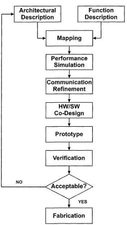
Following th e specification stag e is th e m ap p in g stage, in w hich th e sy ste m ’s functions are p a rtitio n e d an d d irectly m a p p e d to th e chosen sy stem arc h ite c tu re . In ad d itio n , th e h a rd w a re a n d softw are interfaces are also m ap p ed o n to th e a r c h ite c tu re ’s resources. T h e p erfo rm an ce sim u latio n stag e is n ex t, which involves ca rry in g o u t all of th e sim u latio n s for each co m ponent, an d perfo rm in g various verification techniques on th e m a p p e d h ard w are a n d softw are com ponents. T his is done to verify th a t th e m ap p ed system is fu n c tio n a l a n d is cap ab le of m eetin g th e design co n stra in ts. T h e nex t stag e is th e com m u n icatio n refinem ent stag e, in which th e in ter-c o m m u n ica tio n betw een th e various sy stem fu nctions are defined [57], O nce th ese m odelling stages are com pleted, th e system design goes in to a h ardw are-softw are co-design synthesis w here th e com p o n en ts of th e system are synthesized tog eth er. A t th is stage, th e p ro to ty p e of th e em b ed d ed system h as been co n stru c te d , an d th e n goes in to th e verification stage. F u rth e r design ite ra tio n s are p erform ed if th e sy stem does no t m eet th e specified design requirem ents. F a b ric a tio n is th e last stage, in which th e verified system is ta k e n a n d sent off for p ro d u c tio n .
2.4
P la tfo rm -B a sed D esig n
T h e P la tfo rm -B ase d D esign (P B D ) m eth o d o lo g y em phasizes th e use of reusable IP
c o re s a s a p l a t f o r m u p o n w h ic h d e s ig n s a r c c o n s t r u c t e d [54]. T h i s in v o lv e s a d e s ig n -
2. D E S IG N M E T H O D O L O G IE S F O R E M B E D D E D S Y S T E M S
Application Space
Platform Specification
Platform Design-Space
Exploration
Architectural Space
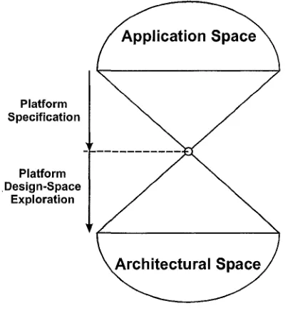
F ig u re 2.4: D esign S pace E x p lo ra tio n
m iddle a p p ro a c h ” [26] as show n in F ig u re 2.4 [56].
2. D E S IG N M E T H O D O L O G IE S F O R E M B E D D E D S Y S T E M S
Platform
Instance
Application
Performance
Numbers
Simulation
Platform
Derivation
Mapping/
Compiling
2. D E S IG N M E T H O D O L O G IE S F O R E M B E D D E D S Y S T E M S
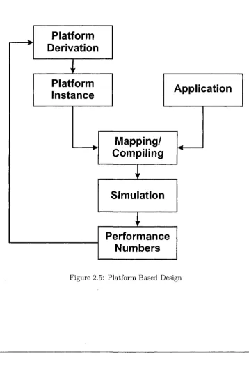
F ig u re 2.5 describes th e P la tfo rm -B a se d D esign m ethodology of em b ed d ed sys tem s [54]. T h e designer s ta r ts by specifying th e p la tfo rm arc h ite c tu re , which o u tlin e s th e p erfo rm an ce co n stra in ts an d th e fu n c tio n a lity of th e en tire sy stem based on th e in te n d e d ap p licatio n . T h is includes th e specification of th e required speed of th e m i croprocessor, m em ory capacity, cache m em ories, etc. From th e defined req u irem en ts, a p la tfo rm in sta n c e is m ad e w hich co n tain s all of th e in s ta n tia te d h ard w are com po n e n ts a n d softw are p ro g ram s required to execute a specific ap p lica tio n . Following th is stag e is th e m ap p in g a n d com piling of th e system , w hich includes h ard w are p la tfo rm synthesis an d th e p ro g ram code generatio n . N ext, th e com piled system goes in to th e sim u la tio n stage, w hen designers te s t all of th e co m ponents to ensure th a t th e y are fu n c tio n in g correctly an d m eetin g th e design co n stra in ts. B ased on th e perfo rm an ce n u m b ers re trie v ed from th e sim u latio n stag e, th e designer can d eterm in e if th e system has satisfied th e specified requ irem en ts. If no t, th e system goes into a n o th e r design ite ra tio n cycle u n til it h as fully m e t all of th e co n stra in ts.
2.5
Sum m ary
C h a p ter 3
Profiling Tools
T h ere is a w ide v ariety of profiling tools available t h a t m easure different perfo rm an ce m etrics an d retrieve diverse sets of profiling inform ation. Section 3.1 discusses profil ing tools an d a prop o sed softw are profiling m eth o d o lo g y for th e design of em bedded system s. T h e sub seq u en t sub-sections classify th e different ty p e s of profilers available as follows: S o ftw are-B ased Profiling (S B P ) Tools, Softw are-B ased M e m o ry Profiling
(S B M P) Tools, H ardw are-C ounter B ased Profiling (H C B P ) Tools a n d F P G A -B a sed Profiling (F P G A -B P ) Tools. In each of th ese categories, a b rief survey of th ese ex isting tools is presented.
3.1
P rofilin g Tools and th e
S o f t w a r e P r o f i l i n g M e t h o d o l o g y
3. P R O F IL IN G T O O L S
specification stag e in w hich all th e fu n ctio n alities of th e system an d th e s u p p o rtin g a rc h ite c tu re to im plem ent t h a t fu n ctio n are defined. U sually em b ed d ed designers have tw o o p tio n s for th e in itia l im p le m e n tatio n of th e ir design based on th e specifi cations. For th e first optio n , th e em bedded sy stem can be entirely im p le m e n ted in h ard w are w hile m oving c e rta in com p o n en ts to th e softw are dom ain, d ep e n d in g on th e execution perfo rm an ce of th o se fu n ctio n s [42]. T h e second o p tio n is to have th e e n tire em bedded system im p lem en ted in softw are [35] a n d invoke a profiler t h a t m easures th e p erfo rm an ce of th e softw are pro g ram . T h e in fo rm atio n provided by th e profiler is used by designers to help th e m choose w hich softw are functions are m ore d esirable for h ard w are im p le m e n tatio n .
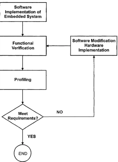
P rofiling tools are used to m easure th e p erfo rm an ce of a p ro g ra m t h a t is ru n n in g on th e ta rg e t processor of an em bedded h a rd w a re p latfo rm . T h ese tools provide use ful in fo rm atio n for designers so th a t th e y can identify ce rtain softw are h o t-s p o ts th a t are causing a perfo rm an ce bottlen eck . D esigners can choose e ith e r to optim ize th e softw are code to allev iate th e perfo rm an ce issue or im plem ent th e c o m p u ta tio n a lly intensive fu n ctio n in th e h ard w are do m ain in o rd e r to achieve a sp eed -u p in p erfo r m ance of th e en tire system . It is im p era tiv e t h a t profilers provide a c c u ra te re su lts an d p ro p e rly d e te c t th ese h o t-sp o ts. T h is can lead to th e creatio n of a b alan ced p a rtitio n betw een th e h ard w are an d softw are com ponents. T h e q u ality of th e em b ed d ed system is en tirely d ep e n d en t on th e efficiency an d th e effectiveness of th e hardw are-softw are p a rtitio n of th e sy ste m ’s com ponents. T h e ap p lica tio n of profiling to o ls has led to a prop o sed Softw are Profiling M ethodology (S P M ) as show n in F ig u re 3.1 [60].
3. P R O F ILIN G T O O L S
NO
YES
^ M eet ^
Requirem ents?,
END S oftw are Im p lem entatio n o f E m bedded System
Profiling
So ftw are M o dification Hardw are Im plem entation Functional
Verification
3. P R O F IL IN G T O O L S
re tu rn feedback a n d p erfo rm an ce s ta tis tic s to th e designer. T h e designer analyzes th e re su lts an d d eterm in es if th e softw are code m eets th e specified p erfo rm an c e con stra in ts. T h a t sam e profiling in fo rm atio n can be used by an a u to m a te d h ard w are - softw are p a rtitio n in g C A D tool [63]. If th e system fails to m eet th e re q u irem en ts, th e designer will try to optim ize th e code o r move ce rtain c o m p u ta tio n a lly intensive fu nctions in to th e h a rd w a re d o m ain as a h a rd w a re accelerator. If necessary, th e en tire m ethodology s ta r ts ag ain u n til th e designer is satisfied w ith th e p erform ance.
E x istin g profiling tools offer different ty p e s of profiling ca p ab ilities a n d su p p o rt different p ro g ram m in g languages. C / C + + profiling tools are com m on, b u t th e re are also tools available t h a t can profile p ro g ram s w ritte n in Ja v a [38, 37]. M en to r Seam less C o-verification en vironm ent provides a profiler t h a t tak es a design w ritte n in S ystem C [13] an d m easures its p erfo rm an ce based on processor u tiliz a tio n , cache efficiency, m em ory h o tsp o ts, b us u tiliz a tio n an d bus m aster co n ten tio n [12].
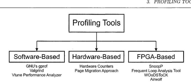
C u rrently, th e re are m an y different kinds of profiling tools t h a t are used to re triev e a v arie ty of profiled in fo rm atio n a b o u t a pro g ram . T h e m ost com m on is function- level profiling w hich m easures th e am o u n t of tim e needed for a fu n c tio n to execute on th e processor. A n o th er ty p e is m em ory-level profiling th a t d eterm in e s w hich func tion, d a ta variable ty p e or in stru c tio n is causing m em ory re la te d problem s: excessive m em ory references, cache m isses, heavy p o in te r dereferencing, b ra n ch in g an d looping in stru ctio n s. F ig u re 3.2 dep icts th e p ro p o sed classification of profiling tools. T h ere are th re e m ain categories: software-based, hardware-based an d F PG A-based. We de scribe each of th ese in d e ta il in th e following sections.
3.2
Softw are B ased P rofilin g (S B P ) Tools
3. P R O F ILIN G T O O L S
Hardware-Based
Software-Based
FPGA-Based
Profilin g T o o ls
G N U ’s gprof Hardware Counters SnoopP
Valgrind Page Migration Approach Frequent Loop Analysis Tool Vtune Performance Analyzer W O0DST0CK
Airwolf
F ig u re 3.2: Profiling Tool C lassification
in sertio n of in s tru m e n ta tio n code. S im ulations ta k e place in v irtu a l en v iro n m en ts th a t sim u la te th e b eh a v io u r of a m icroprocessor as th e softw are code is ru n n in g on a v irtu a l environm ent. T h e in sertio n of in stru m e n ta tio n code allows an S B P to o l to a tta c h itself to th e b in a ry file an d collect p erfo rm an ce in fo rm atio n d u rin g th e execution of a p ro g ram on th e processor. In th is section, we describe an ISS, G N U ’s
gprof [36] a n d In te l’s [11] V tune [45] is given.
3 .2 .1
I n s tr u c tio n S et S im u la to r
In stru c tio n S et S im u lato rs (ISS) are one of th e S B P tools used for profiling so ft w are code ru n n in g in a sim u la te d environm ent. O ne p o p u la r ISS is th e Sim pleScalar
T oolset w hich sim ulates ap p lica tio n code ru n n in g on th e Sim pleScalar c o m p u ter a r c h itec tu re [29], T h e ad v a n ta g es of using an ISS for profiling is t h a t th e designer is able to view th e en tire d a ta flow m ovem ent inside th e m icro p ro cesso r’s registers d u rin g th e sim ulation. I t keeps tra c k of all of th e execution processes, th e c u rre n t in stru c tio n in execution, d a ta m an ip u latio n s, cache accesses an d o th e r re p o rta b le events. T h is does no t require th e softw are code to b e m odified, th erefo re intrusiveness to th e b in a ry file is n o n-existent.
-3. P R O F IL IN G T O O L S
on-a-chip designs since th e y can be very slow to sim u late [51]. T h is could lead to very in a c c u ra te profiles of th e execution tim es of each function. S im u latio n s ca n have varying tim es to com plete d ep en d in g on th e com plexity of th e softw are code. I t m ay ta k e several h o u rs to ru n an en tire sim u la tio n w hich m ay only cover a few seconds of real-tim e, th u s m isrep resen tin g th e en tire execution tim e. D ue to th e increasing com plexity of em bedded system s designs, co n stru c tin g com plex m odels of th e sy s te m ’s com p o n en ts a n d o th e r e x te rn a l environm ents m ay n o t be possible
3 .2 .2
G N U ’s g p r o f
gprof [36] is an open-source profiling to o l t h a t is used on L inux [5] an d U nix [6] w o rk sta tio n s to profile C a n d C + + ap p lica tio n code. It provides two ty p es of profiled o u tp u ts: th e flat profile an d th e call grap h . T h e flat profile is a re p o rt of how m uch tim e th e p ro g ram is sp e n t on each fu n ctio n a n d th e n um ber of tim es t h a t fu n ctio n was called. T h e call g ra p h displays each function, its calling fu n ctio n a n d o th er functions called w ith in t h a t function. To utilize th is profiler, th e designer is req u ired to com pile th e code w ith th e d efau lt debug in stru m e n ta tio n settin g . T h is o p tio n in serts ad d itio n a l in s tru m e n ta tio n code into th e b in ary executable file, as req u ired by
gprof.
D u rin g p ro g ram execution, gprof utilizes th e in serted in s tru m e n ta tio n code to m o n ito r th e p erfo rm an c e o f th e p ro g ram ru n n in g on th e C e n tra l P rocessing U n it (C P U ). T h e in stru m e n ta tio n code allows gp ro f to count th e precise n u m b er of func tio n calls a n d g en e rate th e a p p ro p ria te n u m b er of in te rru p ts to sam ple th e p ro g ram co u n ter (P C ) of th e C P U . It is capable of g e n e ra tin g a profile t h a t a c cu ra te ly counts th e n u m b er of fu nctions t h a t have been called, however, th e re p o rte d execution tim e of each fu n c tio n m ay b e som ew hat in acc u rate .
3. P R O F IL IN G T O O L S
executed on th e processor. B ased on th is value, gprof increm en ts th e ex ecu tio n tim e co u n ter of th e fu n c tio n t h a t is c u rren tly executing by its sam p lin g period. T h is can create in a c c u ra te tim in g resu lts for each fu n ctio n called an d th e execution tim e of th e en tire p ro g ram [68]. T h e accuracy of th e profiled execution tim e is en tirely d e p e n d e n t on th e sam p lin g frequency of th e P C .
3 .2 .3
I n t e l’s V T u n e
In te l’s V T une P erfo rm a n ce A n a ly ze r is an S PB to o l t h a t profiles C / C + + code t h a t is executed on In tel processors [45, 47, 11]. T h e V T une an alyzer fe atu res th re e profiling m odes: Sam pling O ver T im e (S O T ), Call Graph an d C ou n ter M onitor. E ach of th ese m odes is discussed briefly in th e following p a ra g ra p h s.
T h e re are two sam pling m eth o d s t h a t are used by VTune: S a m pling O ver T im e
(S O T ) an d th e P a u se /R e su m e A pplica tio n Program m ing In terfa ce (A P I) [24]. S O T profiles th e softw are code an d shows th e perfo rm an ce re su lts specified “over tim e ” of each th re a d , fu n ctio n an d in stru c tio n u n til th e p ro g ram has co m pleted execution. In ad d itio n , it can d e te c t w hen th e processor is in an idle sta te . T h is allows designers to o ptim ize th e ap p lica tio n code to execute o th e r th re a d s w hen th e processor is n o t executing any th rea d s.
S am pling using th e P a u se /R e su m e A P I [24] requires th e user to in sert c e rta in functions into various p a r ts of th e softw are code. Such fu nctions are VTPauseO , VTResumeO, V T P auseSam plingO , VTResumeSamplingO, CMPauseO a n d CMResumeO T hese fu n ctio n s are used to select c e rta in code regions for profiling.
3. P R O F ILIN G T O O L S
3 .2 .4 S u m m a ry o f S B P T ools
T h e use of th e sam pling tech n iq u e in com m on softw are-based profilers helps to reduce th e ru n -tim e overhead d u rin g profiling. N evertheless, th is can p ro d u ce in a c c u ra te profiled re su lts w hich can p o te n tia lly cre a te a su b -o p tim al p a r titio n of th e em b ed d ed system . T h e use of an ISS can also p ro d u c e in a c c u ra te resu lts since sim u lato rs a re only as go o d as th e sy stem m odel t h a t is being sim ulated. Also, th e sim u latio n tim e m ay n o t a c cu ra te ly m a tc h th e a c tu a l ru n -tim e execution of th e pro g ram . C e rta in S B P tools req u ire th e designer to link th e ir p ro g ram w ith in stru m e n ta tio n code which is in serted a t th e b in a ry level. T h is can lead to an excessive n u m b er of in te rru p t calls w hich m ay cause u n p re d ic ta b le b eh av io u r of th e softw are code ru n n in g on th e em bedded h a rd w a re p latfo rm . A dditionally, th e in stru m e n ta tio n code can lead to an increase in code size a n d m ay p o te n tia lly change th e b eh aviour an d th e perfo rm an ce of th e softw are system .
3.3
Softw are B ased M em ory Profilers (S B M P )
3. P R O F IL IN G T O O L S
to re triev e in stru c tio n s from its own cache m em ory. T his is due to m isp red icted b ra n ch in g in stru c tio n s, heavily n ested dereferencing of m em ory p o in ters a n d looping in stru ctio n s.
M em ory profilers are needed to d e te c t th e p roblem s listed above, so t h a t th e y can be resolved by th e designer. T h ey provide d etailed in fo rm atio n a b o u t w hich fu n c tio n call in th e a p p lic a tio n code is p ro d u c in g m em ory leaks, cache m isses a n d high m em ory referencing. R educing th e n u m b er of m em ory accesses can im prove p erfo rm an ce an d m inim ize p erfo rm an ce overhead [50]. In th is section, th e following m em ory profiling tools are described: Valgrind [14], a n d P u rify [44],
3.3 .1
V a lg rin d
Valgrind, is an open-source G N U profiling to o l for L inux system s [14]. T h is profiler can check th e calls for re ad an d w rites to m em ory, as well as for allo ca tin g an d freeing m em ory using fu nctions such as th e C + + functions new a n d d e l e t e . T h e m ajo r ad v a n ta g e of Valgrind is its ca p ab ility for cache m em ory profiling. It sim ulates th e C P U ’s Level 1 d a ta a n d in stru c tio n level caches as well as Level 2 cache. Valgrind
determ in es a cache h it count for every line of th e p ro g ram t h a t is being tra c e d an d analyzed. It can profile ap p licatio n s of various sizes, from sm all fu nctions to com plex ap p lica tio n system s.
3. P R O F IL IN G T O O L S
Illegal to read, write or free red and blue memory
Red Blue
M em ory / M em ory
M alloc
Free Free
Legal to read and write {or free if allocated by
malloc) Legal to write or free, but
illegal to read
Yellow M em ory
Allocated, Uninitialized Memory
W rite
F ig u re 3.3: R a tio n a l P u rity ’s M em ory Profiling C olour C ode
3 .3 .2
R a tio n a l S o ftw a re ’s P u r ify
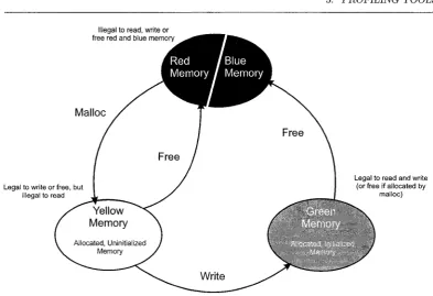
R a tio n a l S o ftw a re ’s P u rify [44] is a softw are-based m em ory profiler t h a t can be used on M icrosoft W indow s [7], U nix [6] an d L inux [5] o p e ra tin g environm ents. T h e to o l helps in solving m em ory problem s a n d d eterm in es th e exact code lo catio n t h a t is causing th e error. T h e kinds of p roblem s th e p ro g ram d e te c ts are m em ory leaks, re ad in g an d w ritin g beyond th e b o u n d s of an a rra y in m em ory, a tte m p ts to free u n a llo ca te d m em ory a n d using u n -in itialized m em ory. P u rify uses a four colour schem e to re p resen t m em ory problem s as show n in F ig u re 3.3 [44]: red, yellow, green an d blue.
3. P R O F IL IN G T O O L S
is a llo ca te d by th e p ro g ram . I t is n o t legal to re a d from it because it is n o t in itialized or does n o t co n tain any valid d a ta . T h e green zone is m em ory th a t has b een w ritte n into an d is available for re ad in g a n d w ritin g d a ta . B lue zone is m em ory t h a t is freed by th e p ro g ram a n d is no longer accessible.
3 .3 .3 S u m m a ry o f S B M P T o o ls
M em ory profiling to o ls are essential for d e te c tin g m em ory leaks, allo catio n a n d de allo ca tio n errors, as well as in stru c tio n s t h a t cause cache re a d /w rite misses. T h e y give th e designer m ore o p tio n s to analyze an d o ptim ize th e softw are code p rio r to p o rtin g it to th e ta rg e t arc h ite c tu re . In ad d itio n , th e y provide m ore d etailed p erfo rm an ce infor m a tio n th a n function-level profilers. T h e p roblem w ith th e c u rren t m em ory profiling tools is t h a t th e y use th e sam e m easu rin g techniques as S B P tools. Som e m em ory profilers req u ire t h a t th e designer include in stru m e n ta tio n code in th e ir ap p lica tio n a t th e b in a ry file. T h is in tro d u ce s th e issue of larg e code sizes an d ru n tim e overhead. Some m em ory profilers use sam pling techniques to sam ple th e h ard w are coun ters an d retriev e th e ir values. As discussed in th e case of softw are-based profiling, sam pling techniques can p ro d u ce in a c c u ra te re su lts an d m ay p o te n tia lly m islead th e designer to im p ro p erly im p lem en t c e rta in fu nctions in th e h ard w are or softw are dom ains.
3.4
H ardw are-C ounter B a sed P rofilin g
(H C B P ) T ools
H a rd w are-C o u n ter B ased P rofiling (H C B P ) to o ls utilize on-chip h ard w are cou n ters
t h a t a r e a v a ila b le o n a d v a n c e d p r o c e s s o r s s u c h a s S u n Ultrasparc [64], In te l P e n tiu m
3. P R O F IL IN G T O O L S
accesses, cache misses, pipeline stalls, ty p es of in stru c tio n s executed a n d etc. H C B P tools do n o t require th e use of in stru m e n ta tio n code since th ese co u n ters a re designed to collect perfo rm an ce in fo rm atio n of th e softw are program . In a d d itio n , very little perfo rm an ce overhead is in tro d u c e d d u rin g ru n tim e execution.
A ccessing these cou n ters requires a un iq u e in stru ctio n . T h e P erfo rm a n c e A d vanced P rogram m ing Interfa ce (P A P I) [28] provides users w ith a high level in terface to access th ese coun ters an d can s u p p o rts m an y different processors [62], I n t e l’s
V T u n e co u n ter m o n ito r provides an in terface for accessing an d utilizing th e h ard w are counters to profile ap p lica tio n code executing on P en tiu m -b ased processors [46].
3.4 .1
H a rd w a re C o u n te rs A p p ro a ch
Itzko w itz et al from S u n M icro system s have described a softw are profiling to o l t h a t utilizes th e h ard w are coun ters in an U ltrasparc-III m icroprocessor [48]. O riginally th is profiling to o l was b u ilt as a n exten sio n of th e S un O ne S tu d io [4] com pilers a n d perfo rm an ce tools, w hich are used for m easu rin g th e p erform ance of softw are code. T hese h ard w are co u n ters are included in th e a rc h ite c tu re an d co n tain different ty p es of event coun ters such as, In stru c tio n s C om pleted, In stru ctio n -ca ch e (1$) M isses, D ata-cache (D$) R ead M isses, D ata-translation-lookaside-bujfer (D T L B ) M isses, E xternal-cache (E$) References, E$ R ead M isses, E$ S ta ll Cycles, an d m any others.
3. P R O F IL IN G T O O L S
re c t ad d ress value, due to th e p ossibility th a t th e previous in stru c tio n was a b ra n ch call. In ste a d of relying on th e value of th e P C , th e profiling to o l tries to find th e p ro p e r values in o th e r re g isters to ca lcu late th e effective ad d ress of th e in stru c tio n t h a t caused th e overflow event. It is n o t g u a ra n te e d success in finding th e address since th e value of th e re g isters m ay have changed once o th e r overflow signals have been delivered to o th e r h a rd w a re counters. D espite w ith th ese draw backs, th e to o l has m an ag e d to find th e p ro p e r in stru c tio n 99% of th e tim e. T h e M C F b en c h m a rk was profiled an d th e feedback pro v id ed enabled a 20% perfo rm an ce im provem ent.
3 .4 .2
P a g e M ig r a tio n A p p r o a ch
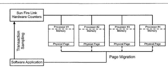
T h e Page M igration A pproach (P M A ), developed by T ik ir et al utilizes h ard w are- co u n ters for profiling m em ory w ith m em ory p ag e -m ig ratin g capabilities [65]. T h e profiler was used on a m ulti-p ro cesso r system b ase d on S u n ’s Sun F ire S erv e r as show n in F ig u re 3.4. E ach sy stem b o ard co n tain e d several processors a n d m em ory. T h e S u n Fire L in k h ard w are co u n ters are used to sam ple th e frequency w ith which each processor “to u ch es” a page of m em ory t h a t is rem ote from th e o n -b o a rd local m em ory hardw are. A t a c e rta in n u m b er of counts specified by th e user for rem o te to u ch in g of m em ory pages, th e profiler h a lts th e execution. It th e n m ig ra te s th a t p a rtic u la r m em ory p age to th e processor t h a t accesses it m ost frequently for re ad a n d w rite o p eratio n s. P M A h as d e m o n stra te d 90% speed im provem ent w hen c e rta in m em ory pages are placed closest to th e processor t h a t requires d a ta from t h a t page.
3 .4 .3
D e s k to p P r o c e s so r P ro filin g C o u n ters
3. P R O F IL IN G T O O L S
P a g e Migration
S o ftw a re A p p lic a tio n S u n F ire L ink H a rd w a re C o u n te rs
P hysical P a g e P ro c e s s o r #3 M emory
P hysical P a g e P ro c e s s o r #1 M em ory
P hysical P ro c e s s o r #2
M em ory
P hysical P r o c e s s o r #4
M em ory
F ig u re 3.4: P ag e M ig ratio n A pproach
c e rtain event occurs or th e y can m easure th e d u ra tio n of an event th a t is c u rren tly ta k in g place on th e processor. In te l P e n tiu m m icroprocessors also co n tain a set of p erform ance h ard w are coun ters [46]. T h ey are also event or tim in g driven an d are accessible th ro u g h I n te l’s V T une [45] profiling tool.
3 .4 .4
S u m m a r y o f H C B P T o o ls
Using h ard w are coun ters for profiling softw are code is beneficial since it does no t in tro d u ce any in stru m e n ta tio n code, leaving th e com piled a p p lic a tio n source code u ntouched. A dditionally, th e y do n o t ad d any p erform ance overhead since th e d a ta collection of th ese co u n ters occurs d u rin g ru n tim e execution of th e softw are. However, th e re a re draw backs w hen using H C B P tools. F irst, som e H C B P to o ls m ay req u ire th e user to reconfigure an d re p ro g ram th e coun ters to d etec t different events, w hich can lead to th e a d d itio n of c e rta in fu nctions a t th e source code level. Secondly, th ey use th e sam p lin g m e th o d to sam ple th e h ard w are counters w hich leads back to th e problem s t h a t were in tro d u c e d w ith S B P tools. T hirdly, h an d lin g of in te rru p ts
a ffe c t t h e g a t h e r e d d a t a s in c e t h e i n t e r r u p t s e rv ic e r o u tin e s ( I S R ) u s e d a d d t o t h e
3. P R O F IL IN G T O O L S
m o n ito rin g events [62].
3.5
F P G A -B a se d P rofiling (F P G A -B P ) Tools
F P G A s are user p ro g ram m a b le in te g ra te d circ u its t h a t offer re aso n ab ly high level of in te g ra tio n , negligible p ro to ty p in g cost an d in sta n ta n e o u s m a n u fa c tu rin g capability. R iding on M o o re’s law [52], F P G A s have grow n in logic ca p acity w hile m a in ta in in g an affordable cost for m an y ap p licatio n s [31]. E m b ed d e d developm ent k its t h a t utilize F P G A s co n tain an ab u n d a n ce of o n -b o a rd resources such as clock m ultip liers, fast m em ory chips, m a th co-processors, etc. T h is m akes th e m an a ttra c tiv e a lte rn a tiv e for ra p id p ro to ty p in g of large em bedded system designs due to th e ir reconfigurability a n d flexibility th a t th e y offer to th e designer.
R esearchers to d a y are developing profiling to o ls th a t can help designers w orking on em bedded sy stem designs using F P G A s. T h e two m a jo r F P G A vendors, A lte ra C o rp o ra tio n [17] an d X ilinx In c o rp o ra te d [72], provide em bedded system developm ent k its w hich use th e Nios II [32] an d M icroB laze [73] soft-core processors, respectively. T hese soft-core processors are in s ta n tia te d on th e F P G A an d used as basic building blocks for designing em bedded system s [66].
F P G A -b a se d profiling (F P G A -B P ) tools also utilize these soft-core processors for profiling. In F P G A -B P tools, th e designer executes th e softw are on th e soft-core processor an d collects th e perfo rm an ce d a ta provided by th e on-chip profiling h a rd ware. T hese tools have pro v id ed im proved re su lts co m p ared to th e p revious profiling tools d escribed earlier. T h e y keep laten c y an d perfo rm an ce overhead a t a m inim um , because th e y are no n -in tru siv e an d require negligible in stru m e n ta tio n . T h ey do n o t
u s e t h e s a m p lin g te c h n iq u e a n d r e q u ir e v e r y m in i m a l p r o c e s s o r c o m p u t a t i o n . T h e s e
3. P R O F ILIN G T O O L S
System Clock
_n_n__
PC
Segm ent Counter
Segm ent Counter
#N Segm ent
Counter Segm ent
Counter
MicroBlaze
CPU
F ig u re 3.5: S noopy’s Profiling A rc h ite ctu re
3.5.1
S n o o p P
SnoopP [60] is an on-chip function-level profiler t h a t was im plem ented on th e X ilinx V irtex -II 2000 F P G A b o a rd . T h is b o a rd is used to im plem ent designs based on X ilinx M icroB laze [73] soft processor. T h e on-chip profiler utilizes th e M icroB laze as a ta rg e t processor. Sno o p P uses a h ard w are profiling arc h ite c tu re t h a t is non-in tru siv e to th e code, such t h a t any ad d itio n a l in stru ctio n s, com m ands or o th e r flags are no t necessary. F ig u re 3.5 d ep icts th e h ard w are a rc h ite c tu re for th e SnoopP profiler.
Sno o p P consists of a v ariab le n u m b er of segm ent counters t h a t are user specified
a n d d e fin e t h e a d d r e s s o f i n s t r u c t i o n s t o b e a n a ly z e d . T h e n u m b e r o f s e g m e n t c o u n t e r s
3. P R O F IL IN G T O O L S
P C > = low address P C O U T P U T B U S
— P C < = high ad dress
R E A D B U S
C o u n te r EN
^ 6 4 -b it T im e C ou nter S Y S T E M C L O C K
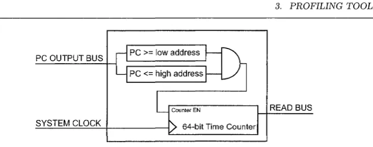
F ig u re 3.6: S noopy’s Profiling C ounter
address is in th e ra n g e of m em ory addresses in w hich th e b in a ry code co rresponding to th e fu n c tio n resides. T h is is d eterm in e d by th e c o m p a ra to rs inside each segm ent counter. If th is co n d itio n is tru e , th e c o m p a ra to r sends an en able signal to th e hard w are co u n ter which utilizes th e p ro c esso r’s sy stem clock to co u n t th e n u m b er of clock cycles th e fu n ctio n h as used. T h is gives th e designer th e precise n u m b er of clock cycles t h a t th e p a rtic u la r fu n ctio n needs to execute on th e processor. S n o o p P ’s
an d g p r o f’s re su lts were com pared, a n d it was show n th a t SnoopP was significantly m ore a c cu ra te . A dditionally, Sno o p P does n o t slow dow n th e p erfo rm an ce of eith er th e softw are or th e profiling process.
3 .5 .2
F req u en t L o o p A n a ly sis T o o l (F L A T )
Frequent Loop A n a lysis Tool (F L A T ) is a to o l t h a t d etec ts fu n ctio n s in softw are t h a t heavily use loops [40]. In m o st cases, loops use 90% of th e execution tim e while c o n stitu tin g only 10% of th e en tire softw are code. F L A T searches for th ese critical regions an d records th e execution frequency of each loop-intensive fu n c tio n into a cache-like h ard w are a rc h ite c tu re t h a t is im plem ented in an F P G A . A block d iag ra m of th e F L A T a rc h ite c tu re is show n in F ig u re 3.7.
U sually a loop in stru c tio n is typically d en o ted as a Sh o rt B ackw ards B ranch
3. P R O F IL IN G T O O L S
Read/Write Read/W rite
A d d re s s A d d re s s
Data Data
SBB
Increm ent M icroblaze
CPU
Frequent Loop Cache
C ontroller
Frequent Loop Cache
F ig u re 3.7: F req u en t Loop A nalysis Tool
value of th e SBB is a n egative address offset. T h e Frequent Loop Cache (F L C ) sto res th e execution frequency of each loop fu n ctio n a t th e index m em ory lo catio n t h a t is based on th e SBB value. A cache controller, called th e Frequent Loop Cache C on troller, keeps th e d a ta u p d a te d w ith th e la te st values. F L A T does n o t req u ire th e use of in stru m e n ta tio n code or any sam pling techniques. N onetheless, th e accu racy of th e loop d etec tio n relies on th e size of th e on-chip cache in th e F P G A .
3 .5 .3
W o O D S T o C K
W O o D S T O C K [59] (W a tc h es O ver D ata ST rea m in g O n C om puting elem en t lin K s),
is a profiling to o l th a t m o n ito rs th e com m u n icatio n dataflow betw een C o m p u tin g P rocessor E lem ents (C P E s) as show n in F ig u re 3.8
W O oD ST oC K m o n ito rs th e d a ta flow betw een each C P E by ad d in g m o n ito rs to th e circu it w hich ru n in real tim e. T h e d a ta link betw een each elem ent of th e sy stem is created by F ast S im p lex L in k s (FSL s) [71], available in X ilin x ’s M icroB laze [73] soft core processor. FSLs allow stre a m in g an d buffering o f-d a ta betw een th e h ard w are co m ponents of th e system . T h e profiler utilizes th e links to m easure th e stre a m of
d a t a b e t w e e n e a c h C P E . I t m e a s u r e s t h e n u m b e r o f r u n - t i m e e x e c u t io n c lo c k cycles to see w hich C P E is sta lle d or sta rv e d for d a ta .