Low RCS Microstrip Patch Antenna Using
Complementary Split-Ring Resonators
Priyanka R Ravi 1,V A Libimol2, Sreelatha K K3, Nisamol T A3,Dr C K Aanandan 4
P.G Student, Department of Electronics, Cochin University of Science and Technology, Kerala, India 1
Microwave Propagation Research Laboratory, Dept. of Electronics, Cochin University of Science and Technology,
Kerala, India2
P.G Student, Department of Electronics, Cochin University of Science and Technology, Kerala, India 3
Professor, Department of Electronics, Cochin University of Science and Technology, Kerala, India 4
ABSTRACT: Amicrostrip antenna with low RCS is proposed in this paper. RCS reduction is accomplished by
employing complementary split ring resonator in the ground plane of the proposed antenna. A conventional antenna is designed and simulated for a frequency of 11.5GHz.As compared to the conventional microstrip antenna, the monostatic RCS can be reduced as much as 15dBwhile preserving almost the same radiation characteristics.
Measured results acceptably agree with the simulated results.
KEYWORDS: Complementary split-ring resonator (CSRR), microstrip patch antenna, radar cross section (RCS)
reduction.
I. INTRODUCTION
The radar cross-section (RCS) is an important constraint for the design of modern aircrafts, missiles, helicopters, ground military vehicles, launchers, and other important strategic installations. The accomplishment with which a radar system can detect a target depends primarily on how much of electromagnetic energy illuminating a target is reflected back to the radar [1]. In strategic applications it is crucial to reduce the RCS of air targets to preserve the low observable nature. Meanwhile the onboard antennas cause a substantial contribution to the overall RCS of airborne vehicle, the designing of antennas have to be done judiciously to meet low RCS requirement. The study of techniques allow reducing the RCS of antenna is therefore of great practical interest.
The RCS reduction technique for antenna system proposed in this paper is based on the loading of Complementary split-ring resonator (CSRR)to the antenna. The idea which is trying to implement here, is to replace the ground plane of antenna with suitable CSRR element. The complementary split-ring resonators are spatial filters of electromagnetic waves, which can be used to improve the antenna performance and reduce the RCS effectively. Thus, it is possible to make the antenna operational for a particular resonant frequency and remains inactive for all other frequencies.
ISSN (Online) : 2319 - 8753
ISSN (Print) : 2347 - 6710
International Journal of Innovative Research in Science, Engineering and Technology
An ISO 3297: 2007 Certified Organization Volume 6, Special Issue 6, March 2017 2ND National Conference on Future Technologies in Power, Control and Communication Systems (NFTPCOS-17)
23rd - 24th March 2017
Department of Electrical & Electronics Engineering, College of Engineering Perumon, Kollam, Kerala – 691601, India
Mushroom-like electromagnetic band gap (EBG) structures are incorporated to attain out-of-band RCS reduction [4], [5]. Even though the backward RCS of the patch array antenna with EBG can be reduced, its directivity is 2 dB inferior. Besides, using fractal structure [6], modifying the antenna structure [7, 8], and using bionics principle [9] the RCS of antennas can be reduced.
Using the SRR and CSRR structure low pass filter [10], high pass filter [11], and so on can be implemented. In this paper, the in-band RCS reduction of micro stripe antenna is realized by the use of a new compact CSRR structure.
II. COMPLEMENTARY SPLIT-RING RESONATOR
In modern years CSRR metamaterial element along with patch antenna is used for antenna miniaturization, RCS reduction and much more. Complementary split rings resonators (CSRRs) are proposed by Pendry [12].Negative- effective permittivity can be anticipated for any CSRR-based medium. By etching the rings or loops in the ground plane, just beneath the conductor strip CSRR can be realized. It is equivalent to a parallel LC resonant tank circuit with a resonant frequency given by
f=1/ (2πLeqCeq)
where Leq and Ceq are the equivalent inductance and capacitance of the CSRR.
In order to realize the effect of RCS reduction, the traditional CSRR needs to be minimized. For a resonant frequency of 11GHz, the compact CSRR is designed and simulated.
Table 1.The parameters of the CSRR unit cell.
Parameters D1 D2 D3 D4 D5 D6
Value (mm) 5.95 7 3.25 1 1.1 2.15
Parameters D7 D8 D9 D10 D11
Value (mm) .7 1.3 .3 3.15 .7
The incident wave within the CSRR’s band will be reflected while the incident wave outside of the CSRR’s stop-band will transmit through the CSRR without any hindrance. This can be useful for RCS reduction. The geometry of CSRR unit cell is shown in Fig.1. In Fig.2, it is clearly found that CSRR presents a stop-band characteristic of in the vicinity of 10.8GHz.To validate the performance of the proposed stop band characteristic, a four-period prototype device has been designed, simulated and measured.
In order to investigate the influence of CSRR on radiation characteristics and RCS of microstrip antenna, a variety of simulations have done. As the CSRR has an opening end, the structure is asymmetric. Depending upon the orientation of the opening end, the antenna performance is possibly affected, that can be verified by simulations.
Fig 1.Geometry of each CSRR unit cell. Fig 2.S-parameters of the CSRR cell.
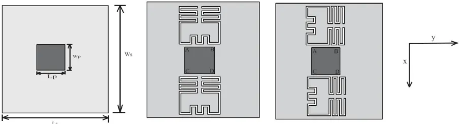
In Fig. 3, on both sides of the line AB and CD two CSRRs are etched. In Figs. 3(b), (c), the orientation of the opening end is along x axis and y axis, respectively. In Fig. 4 and Fig. 5, the simulated S11 and radiation patterns are shown respectively under three different conditions. From the current distribution as shown in Fig.6, it is definite that the orientation of the opening end should be parallel to the y axis.
ISSN (Online) : 2319 - 8753
ISSN (Print) : 2347 - 6710
International Journal of Innovative Research in Science, Engineering and Technology
An ISO 3297: 2007 Certified Organization Volume 6, Special Issue 6, March 2017 2ND National Conference on Future Technologies in Power, Control and Communication Systems (NFTPCOS-17)
23rd - 24th March 2017
Department of Electrical & Electronics Engineering, College of Engineering Perumon, Kollam, Kerala – 691601, India
Fig 5. Comparisons of the simulated radiation patterns of antennas with CSRRs with different orientations of the opening end.
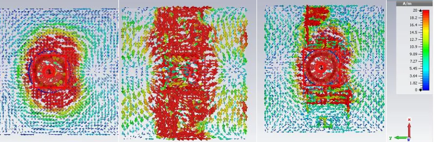
Fig6.Current distribution on the ground of the antenna at 5 GHz, (a) without CSRRs, (b) the orientation of the opening end along y-axis, (c) the orientation of the opening end along x-axis
Fig 7. Geometry of microstrip antenna with CSRRs etched on the ground.
With a center frequency of 11.5 GHz, a low RCS microstrip antenna with CSRRs is shown in Fig. 7.The parameter G1=3.9mm.In order to simulate the unit cell the boundary conditions are set as follows.
Xmin, Xmax=electric Ymin, Ymax=magnetic Zmin, Zmzx=open (add space)
(a) xoz plane b) yoz plane
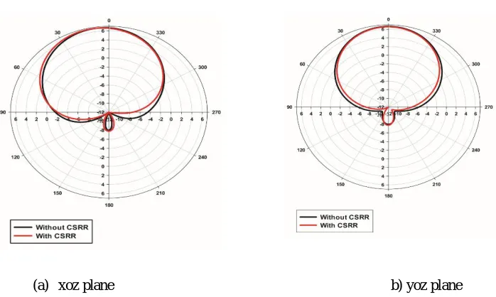
Fig 8. Comparisons of the simulated radiation patterns of antennas with and CSRR
The gain of the antenna with and without CSRRs in the normal direction (z-axis) is 4.85 dB and 5.54 dB, respectively. The gain loss is 0.69 dB at 11.5 GHz, which is less than 1 dB. The gain loss is due to the energy leakage occurs whilechanging the ground with the CSRR structure. Fig. 8 gives the radiation patterns of two antennas. From the Fig. 8it is concluded that the main lobes of two radiation patterns are in fine agreement both inxoz-plane and yoz-plane.
ISSN (Online) : 2319 - 8753
ISSN (Print) : 2347 - 6710
International Journal of Innovative Research in Science, Engineering and Technology
An ISO 3297: 2007 Certified Organization Volume 6, Special Issue 6, March 2017 2ND National Conference on Future Technologies in Power, Control and Communication Systems (NFTPCOS-17)
23rd - 24th March 2017
Department of Electrical & Electronics Engineering, College of Engineering Perumon, Kollam, Kerala – 691601, India
(a) Top View (b)Bottom View
Fig 9. Photograph of the microstrip antennas with CSRRs etched on the ground.
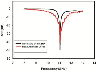
The simulated and measured radiation characteristics are compared in this section. Figure 10 shows the S11 parameters of the reference and proposed antennas. It is observed that the measured results are agreed with the simulated results.
Fig 10.Comparison of simulated and measured S11 of antennas with CSRR.
The resonant frequency of the patch antenna without CSRRs is 11.2 GHz. Fig.9 shows the measured reflection coefficient and radiation characteristics of the patch antenna. It is seen from Fig. 10, that themeasured reflection coefficient is −40dB.The measured radiation patterns are shown in Fig. 11. Once more, a better agreement between the simulated and measured results is obtained. Alike, the minor difference between them is caused due to its fabrication tolerance and measurement error.
(a) xoz plane (b) yoz plane
To illustrate the variation of in-band RCS versus the theta angle, the low, central and high frequency points are chosen, respectively. Figure 12(a) shows that in the normal direction the in-band RCS can be reduced as much as 15 dB at 11.5 GHz in the xoz plane. It is also shown that the RCSs have efficiently reduced within the angular ranges [−25◦, 25◦]. Moreover, due to the excitation of the slots, the in-band RCS of the proposed antenna increases within the angular ranges [50◦, 100◦] and [−100◦, -50◦].
Figure 11(b) shows the in-band RCS for yoz plane. It is seen that in yoz plane also RCS gets reduced considerably as 15 dB at 11.5 GHz. It is also shown that the RCSs have efficiently reduced within the angular ranges [−25◦, 25◦].
Moreover, Figure 12 shows that due to the excitation of the slots the in-band RCS of the proposed antenna increases within the angular ranges [40◦, 100◦] and [−100◦, 40◦].
The CSRRs are resonating at the resonance frequency of patch antenna, which leads to the current to be rearranged. But due to the larger current on the ground plane, the antenna has larger back lobes. The RCS of the antenna greatly depend on the numbers of the CSRRs unit cells and the distance between the antenna and the CSRR unit cells.
(a) xoz plane (b) yoz plane
Fig 12. Comparisons of monostatic RCS between the reference antenna andthe proposed antenna
ISSN (Online) : 2319 - 8753
ISSN (Print) : 2347 - 6710
International Journal of Innovative Research in Science, Engineering and Technology
An ISO 3297: 2007 Certified Organization Volume 6, Special Issue 6, March 2017 2ND National Conference on Future Technologies in Power, Control and Communication Systems (NFTPCOS-17)
23rd - 24th March 2017
Department of Electrical & Electronics Engineering, College of Engineering Perumon, Kollam, Kerala – 691601, India
can be employed in low-RCS platforms.
IV. CONCLUSION
A novel microstrip patch antenna is considered as the test case to confirm the strategy for RCS reduction. A microstrip antenna with four CSRR’s etched on the ground plane is presented. Antenna with and without CSRR is simulated and fabricated. The results show that it is promising to attain RCS reduction at the resonant frequency of the reference antenna.
REFERENCES
[1] E. F. Knott, J. F. Shaeffer, and M. T. Tuley, Radar Cross Section. Raleigh, NC, USA: SciTech, 2004
[2] G. Simone, F. Costa, and A. Monorchio, “Low-profile array with reduced radar cross section by using hybrid frequency selective surfaces,”
IEEE Trans. Antennas Propag., vol. 60, no. 5, pp. 2327–2335,May 2012.
[3] P. K. Panda and D. Ghosh, “Mushroom-like EBG structures for reducing RCS of patch antenna arrays,” in Proc. Int. Conf. Microw.Photon.,
Dec. 2013, pp. 1–4.
[4] H. K. Jang, J. H. Shin, and C. G. Kim, “Low RCS patch array antenna with electromagnetic bandgap using a conducting polymer,” in Proc.Int.
Conf. Environ. Eng. Appl., Sep. 2010, pp. 140–143.
[5] Liu, Y., S.-X. Gong, and H.-B. Zhang, A novel fractal slot microstrip antenna with low RCS,"
IEEE Antennas and Propagation Society International Symposium, 2006.
[6] Jia, Y., Y. Liu, S.-X. Gong, T. Hong, and D. Yu, Printed UWB end-¯re Vivaldi antenna with low
[7] RCS," Progress In Electromagnetics Research Letters, Vol. 37, 11, 2013.
[8] Hong, T., S.-X. Gong, W. Jiang, Y.-X. Xu, and X. Wang, A novel ultra-wide band antenna with
reduced radar cross section," Progress In Electromagnetics Research, Vol. 96, 299-308, 2009.
[9] Jiang, W., Y. Liu, S.-X. Gong, and T. Hong,Application of bionics in antenna radar cross section
reduction," IEEE Antennas and Wireless Propagation Letters, Vol. 8, 1275,1278, 2009.
[10] V.S. Khushwah, G.S.Tomar, S.S.Bhadauria, “Designing stepped impedance microstrip low pass filter using artificial neural network at 1.8 GHz
” International Conference On Communication System And Technologies 2013
[11] Pang Chunhui, Li Qiliang, Liu Jin Xian” A novel highpass filter based on complementary split ring resonators “2015 IEEE 12th International
Conference on Electronic Measurement & Instruments
[12] Pendry, J., Magnetism from conductors and enhanced nonlinear phenomena," IEEE Transactions