SMITH, KELLI L. Linear Concentrated Abrasion Test Method Development for Assessing Performance and Durability of Rescue Hoist Gloves. (Under the direction Dr. Cassandra Kwon and Dr. Bryan Ormond).
Helicopter rescue hoist operators have a specialized need for hand wear to protect against damage from the hoist’s cable wire rope—with one hand the hoist operator manipulates a
Durability of Rescue Hoist Gloves
by Kelli L. Smith
A thesis submitted to the Graduate Faculty of North Carolina State University
in partial fulfillment of the requirements for the degree of
Master of Science
Textile Chemistry
Raleigh, North Carolina 2019
APPROVED BY:
_______________________________ _______________________________ Dr. Cassandra Kwon Dr. Bryan Ormond
Committee Co-Chair Committee Co-Chair
ii DEDICATION
I would like to dedicate this thesis to the amazing support system that pushed me to survive and eventually thrive in my academic endeavors, specifically:
• my Mom, Lynn – thank you for always being there for me to listen and talk through any problems I was facing, regardless of the time of day or my inability to make sense. Without you, there is no way I would gotten this far. When I grow up, I want to be as awesome as you.
• my baby sister, Jacki – thank you for giving me the best pep talks and not letting me quit school to go live in the woods. You kept me sane through humor and
understanding.
• to my partner, Jerry – thank you for being my alarm clock, cheerleader, proofreader, grubhub, and my everything. Without your love and support, I would probably still be curled up in the dungeon somewhere easily. You can totally claim this is your thesis as well because you definitely are the main reason it’s written.
• to my Aunts: Ruth, Lois, and Edna – thank you for always thinking of me and
checking on me during this process. Talking about my research with you allowed me to stay excited about my work, even at the times when I felt the most burnt out. • to my sister-outlaw, Natasha – thank you for always checking on me and being a
cheerleader when I was down. I swear we’ll eventually get out of school! • to my niece, Kara – thank you for telling me about all the fun science things you
iii • to my best friends: Shreeram, Victoria, Lilly, Vicky, Brandon, Bradly, and Ryan –
thank you for letting me talk your ears off about all this crazy stuff, and being there for me when I needed to vent. You have no idea how vital those little conversations were to my sanity. You really are the best.
• to Birgit – thank you for being the best listener and sounding board that I could have asked for. Talks that we had have shaped me in ways that I hope will make you proud someday.
• to my TPACC family – thank you for listening to me discuss my research and anything else that I needed to get off my chest.
iv BIOGRAPHY
v ACKNOWLEDGEMENTS
I would like to express my appreciation and gratitude to the members of my research committee for the guidance they have provided me over the past two years. I would like to thank Dr. Cassandra Kwon for serving as my research co-advisor, allowing me to find my footing in my research, and keeping me grounded when I was struggling against myself. I would also like to thank Dr. Bryan Ormond for serving as my research co-advisor and believing in me when I genuinely couldn’t believe in myself. Without Dr. Kwon and Dr. Ormond, I would not be pursuing the path that I am currently on, and I am forever grateful for the dynamic we have. Additionally, I would like to thank Dr. Roger Barker and Dr. Don Thompson for serving on my research committee and providing valuable guidance through my thesis development. I would also like to thank Dr. Blan Godfrey for the guidance with JMP and statistical analysis, and Teresa White with physical testing support and good conversation.
I would also like to acknowledge and thank all of the members of the TPACC family for their support. I am grateful for the talks from each and every one of them, and hope to provide support back someday when any of them need it.
I would like to thank HDM for providing the financial support for the project, and for allowing me to live with the cable abrader for months.
vi TABLE OF CONTENTS
LIST OF TABLES ... viii
LIST OF FIGURES ... ix
Contents LIST OF TABLES ... ix
LIST OF FIGURES ... x
Chapter 1 . Introduction ... 1
1.1. Purpose ... 1
1.2. Need for Research ... 1
1.3. Research Objectives ... 3
Chapter 2 . Rescue Helicopter Hoist Operations ... 5
2.1. Rescue Helicopter ... 5
2.2. Rescue Helicopter Crew Members ... 6
2.3. Rescue Hoist Operator Tools ... 7
2.3.1. Standard Helicopter Crew Personal Protective Equipment ... 8
2.3.2. Helicopter Hoist Equipment ... 11
2.4. Essential Hoist Glove Qualities ... 13
2.4.1. Abrasion Resistance and the Importance of Durability ... 14
2.4.2. Flexibility and the Importance of Dexterity... 15
2.5. User Wear Considerations ... 18
Chapter 3 . Review of Abrasion Test Methods and Approaches ... 20
3.1. Introduction ... 20
3.1.1. Abrasion Defined ... 20
3.1.2. Mechanisms of Abrasion ... 21
3.2. Test Methods for Evaluating Abrasion Resistance—Investigating Standard and Modified Approaches ... 21
3.2.1. ASTM D4157– Oscillatory Cylinder Method ... 23
3.2.2. ASTM D3884 - Rotary Platform, Double Head Method ... 26
3.2.3. ASTM D3886 - Inflated Diaphragm Apparatus ... 29
3.2.4. ASTM D4966 - Martindale Abrasion Tester Method... 31
3.2.5. ASTM D3885 - Flexing and Abrasion Method ... 33
3.2.6. ASTM D6770 - Hex Bar Method ... 36
3.2.7. Modified Abrasion Test Methods ... 38
vii
3.3. Cable Abrader Apparatus Overview ... 42
3.4. SuperFabric™ ... 44
Chapter 4 . Linear Concentrated Abrasion Test Method Developmet With Cable Abrader Apparatus ... 46
4.1. Introduction and Background ... 46
4.1.1. Cable Abrader Apparatus ... 46
4.2. Materials and Methods ... 54
4.2.1. Materials ... 54
4.2.2. Methods... 55
4.3. Hypotheses ... 68
4.4. Results and Discussion ... 69
4.4.1. Results ... 69
4.4.2. Discussion ... 73
4.5. Conclusions ... 85
Chapter 5 . Material Assessment of Abrasion Resistance Using Linear Concentrated Abrasion Test Method With Cable Abrader ... 87
5.1. Introduction and Background ... 87
5.2. Materials and Methods ... 87
5.2.1. Materials ... 87
5.3. Hypotheses ... 94
5.4. Results and Discussion ... 95
5.4.1. Results ... 95
5.4.2. Discussion ... 99
5.5. Conclusions ... 102
Chapter 6 . Viability of Abrasion Test Methods for Helicopter Hoist Cable Representation .... 103
6.1. Introduction and Background ... 103
6.1.1. Wyzenbeek Abrasion Tester ... 103
6.1.2. Taber® Abraser... 104
6.1.3. Cable Abrader ... 105
6.2. Materials and Methods ... 106
6.2.1. Materials ... 106
6.2.1.1. Selection of Materials ... 106
6.2.2. Methods... 109
6.3. Hypotheses ... 109
viii
6.4.1. Results ... 110
6.4.2. Discussion ... 111
6.5. Conclusions ... 114
Chapter 7 . Conclusions and Recommendations... 116
7.1. Test Development Conclusions ... 116
7.2. Material Comparison Conclusions ... 117
7.3. Test Method Comparison Conclusions ... 118
7.4. Recommendations ... 119
7.5. Future Work ... 120
Chapter 8 . References ... 122
Appendix A: Cable Abrader Standard Operating Procedure ... 125
Appendix B. Cable Run Data Record Sheet Template ... 132
ix LIST OF TABLES
Table 2.1. Rescue Hoist Helicopter Aircrew Member Positions ...7 Table 3.1. Reference chart for common ASTM standard test methods used
for evaluating textile abrasion resistance. ... 23 Table 4.1. Cable abrasion testing sample material information. ... 55 Table 4.2. Linear Concentrated Abrasion Tester (cable abrader) sample and
testing information. ... 55 Table 4.3. Calculation method for total abraded length for linear concentrated
abrasion test method. ... 61 Table 4.4. Calculation method for cable abrader cycles for linear concentrated
abrasion test method. ... 62 Table 4.7. Cable abrader testing results for two layer laminated polyester samples
machine run time in minutes, cable length abraded in feet, and calculated
speed in ft/min... 70 Table 4.8. Cable abrader testing results for two layer laminated polyester
samples set sample pressure in ftlb, pressure variation experienced by
the sample, and cable deflection in inches at 10 ftlb sample pressure. ... 71 Table 4.9. Mass loss in grams for two-layer laminated polyester samples
on the cable abrader. ... 72 Table 4.10. Quantiles for measured cable deflection examined using
JMP statistical software. ... 84 Table 4.11. Summary statistics for cable deflection analyzed in JMP software... 84 Table 5.1. Reference chart of materials used for testing via linear concentrated
abrasion method with cable abrader. ... 90 Table 5.2. Baseline leather sample results for cable abrader testing, with
machine run time in minutes, abraded length in feet, and calculated
cable speed in feet per minute. ... 95 Table 5.3. Baseline leather sample results for cable abrader testing,, with sample
set pressure in ftlb, sample pressure difference in ftlb during cable
run, and cable deflection in inches at 10 ftlb sample pressure... 96 Table 5.4. Baseline glove sample results for cable abrader testing, with
machine run time in minutes, abraded length in feet, and calculated
cable speed in feet per minute. ... 96 Table 5.5. Baseline glove sample results for cable abrader testing, with
sample set pressure in ftlb, sample pressure difference in ftlb
during cable run, and cable deflection in inches at 10 ftlb sample pressure. ... 97 Table 5.6. SuperFabric™ sample results for cable abrader testing, with
machine run time in minutes, abraded length in feet, and calculated
cable speed in feet per minute. ... 97 Table 5.7. SuperFabric™ sample results for cable abrader testing, with
sample set pressure in ftlb, sample pressure difference in ftlb
during cable run, and cable deflection in inches at 10 ftlb sample pressure. ... 98 Table 6.1. Reference chart of materials used for testing for cable
x LIST OF FIGURES
Figure 1.1. Rescue hoist operator controlling hoist cable with gloved hand during live
training. ... 2
Figure 2.1. (Left) UH-60 Black Hawk rescue helicopter and (Right) UH-72A Lakota rescue helicopter airframe.[1]... 5
Figure 2.2. UH-60 Black Hawk internal hoist system (left) & UH-72 Lakota external hoist system (right). ... 6
Figure 2.3. Hoist operator (left, holding cable), rescuer (center), and copilot (right) during training exercises. ... 7
Figure 2.4. Flight helmet configuration for helicopter hoist rescue operator. ... 8
Figure 2.5. Flame resistant flight suit worn by helicopter aircrew [32]. ... 9
Figure 2.6. Summer flyer style flight glove worn by rescue helicopter aircrew. ... 10
Figure 2.7. Helicopter hoist control pendant. ... 11
Figure 2.8. Over glove style hoist glove worn without flight glove underneath. ... 13
Figure 2.9. Hole caused in work glove via thumb gusset abrasions. ... 14
Figure 2.10. Over glove style hoist glove configurations: stand-alone (left), summer flyer flight glove (center), and hoist glove over flight glove system (right). ... 15
Figure 2.11. Zephyr International photograph of hoist cable “birdcaging” and needing immediate replacement [2]. ... 16
Figure 2.12. Responder modified work glove for use in hoist operations, with two fingers and the thumb cut out of the full glove. ... 18
Figure 3.1. Wyzenbeek abrasion testing apparatus, side view. ... 24
Figure 3.2. Abraded area for samples tested with Wyzenbeek abrasion tester... 25
Figure 3.3. Taber® abrasion testing apparatus. ... 26
Figure 3.4. Abraded area for samples tested with Taber® abraser. ... 28
Figure 3.5. Inflated Diaphragm Abrasion Tester diagram [19]. ... 29
Figure 3.6. Abraded area for samples tested with inflated diaphragm abrasion tester. ... 30
Figure 3.7. Martindale abrasion testing apparatus. ... 31
Figure 3.8. Abraded area for samples tested with Martindale abrasion tester. ... 32
Figure 3.9. Flexing and Abrasion Tester in the Wilson College of Textiles’ Physical Testing Laboratory at NC State University. ... 34
Figure 3.10. Abraded area for samples tested with Flexing and Abrasion tester. ... 35
Figure 3.11. Webbing Abrasion Tester with hex bar [24]. ... 36
Figure 3.12. Abraded area for samples tested with Webbing abrasion tester. ... 37
Figure 3.13. Cable abrader diagram side view: cable reels, gear cable, and sample mount (shown red). ... 43
Figure 3.14. Sample mount (shown in red) detail diagram: left showing face of sample mount, and right showing sample mount on cable at tension. ... 44
Figure 3.15. SuperFabric™ side view showing material flexibility and protective coverage by the guard plate [48]. ... 45
Figure 4.1. Cable abrader apparatus with sample mount area enclosed ... 47
xi Figure 4.3. Cable abrader diagram, “Cable Up” configuration, front reel loaded
with cable, cable direction passing up vertically across the sample
mount and wrapping around the back reel. ... 49 Figure 4.4. Cable abrader diagram, “Cable Down” configuration, back reel loaded
with cable, cable direction passing down vertically across the sample
mount and wrapping around the front reel. ... 50 Figure 4.5. Side view of sample mount area. White arrow shows the sample mount
track projection, while the black arrow shows the path of the sample
into the cable at tension. Cable location accented in green dashed line to indicate cable location. ... 51 Figure 4.6. Sample mount disconnected from load cell showing red silicone
component used for indicator (left), and hook and loop straps used
to secure the sample top and bottom to the sample mount area (right). ... 52 Figure 4.7. Sample of 2-layer laminated polyester cut in new shape placed on
sample mount prior to equipping on cable abrader. ... 52 Figure 4.8. Screenshot of one cable run duration, monitoring sample pressure (ftlb). ... 54 Figure 4.9. Progression of cable abrader sample shape: original (top left),
simplified (top center), vertical length adjusted (top right), and
optimized sample shape (bottom center). ... 57 Figure 4.10. Polyester base material shown at material failure endpoint. Sample
is shown on mount after four cable abrader cycles (left), with close up
detail to show failure indicator visual of red silicone sample mount (right). ... 58 Figure 4.11. Cable abrader run data example entry for the 10th cable abrader
cycle in Cable Up configuration. ... 59 Figure 4.12. Top view of measuring cable deflection using a ruler for the cable
abrader, shown at the neutral state with no sample pressure applied, and
the cable at-tension position at one inch from the sample mount base frame. ... 67 Figure 4.13. 2 layer laminated polyester sample after four cable abrader cycles. ... 75 Figure 4.14. Abrasion concentration map for two layer laminated polyester
samples tested using the cable abrader apparatus. Red shows the highest amount of abrasion observed, and violet shows the
lowest amount of abrasion observed. ... 77 Figure 4.15. Mean distribution of cable abrader difference between maximum
and minimum amount of pressure experienced by samples in ftlb. ... 82 Figure 4.16. Mean distribution of cable abrader difference average calculated
speed in feet per minute experienced by 2-layer laminated polyester samples. ... 83 Figure 4.17. Mean distributions of cable deflection (in) at 10 ftlb sample pressure
for cable abrader testing.(N=47) ... 85 Figure 5.1. Sample template for linear concentrated abrasion test method
using cable abrader apparatus. ... 93 Figure 5.2. Mean distribution of set sample pressure in ftlb for all tested
sample runs (N=2078). ... 100 Figure 5.3. One-way analysis of difference between minimum and maximum sample
1 CHAPTER 1 . INTRODUCTION
1.1 Purpose
The linear concentrated abrasion apparatus, or cable abrader, is a new, specialized
machine that pulls steel cable rope across a material sample to mimic the abrasive mechanism of a helicopter rescue hoist cable. The main purpose of this work is to develop a test method for the cable abrader apparatus that can produce results that are repeatable and specific to end-use
application. Using the developed test method for the cable abrader will allow for a sample
material comparison that will accurately simulate hoist operation conditions in a repeatable manner that would not be possible using other abrasion test methods prior to the invention of the cable abrader apparatus. Materials assessed with the cable abrader will be evaluated in terms of abrasion resistance before being integrated in a new rescue hoist glove prototype design.
1.2 Need for Research
2 glove utilized can vary between operators depending on personal preferences. Currently, most of these gloves are made with leather, though the materials of different hoist glove types can vary, as can the durability. Even the most durable glove for rescue hoist operations wear very quickly after only a handful of rescue missions. Aside from the protective failure that occurs when a glove shreds, the leather itself can work its way into the core of the hoist cable, swelling under moist conditions, and potentially fouling the hoist cable. Using a more hydrophobic alternative material to leather with would potentially provide equal durability and maintain the integrity of the hoist cable. The Department of Homeland Security (DHS) released a broad agency
announcement (BAA) calling for proposed solutions to this issue, aiming for more durable hoist gloves that also would not reduce the operator’s range of motion. One of the gloves currently used by hoist operators can be seen in action in Figure 1.1.
Figure 1.1. Rescue hoist operator controlling hoist cable with gloved hand during live training.
3 considering the specific type of abrasive conditions experienced with the hoist cable in action. While there are several various abrasion testing methods and specialized abrasion systems in existence, there currently are no abrasion techniques that would accurately simulate the pattern of abrasion incurred from hoist operations. Using the cable abrader apparatus with a developed standardized testing method would allow for a side-by-side abrasion resistance comparison of glove prototype materials in terms of both consistent laboratory results and realism to hoist operating conditions.
1.3 Research Objectives
The objectives of this research were to study how the linear concentrated abrasion apparatus (cable abrader) could be used to evaluate glove prototype materials in an environment that simulates conditions in the field, while also being able to show consistent, repeatable results. The hoist glove cable wear pattern is mimicked by applying pressure to the sample via cable tension, and the data is collected in terms of cycles to failure that directly corresponds with helicopter hoist cycles. Utilizing cable rope and abrasive conditions similar to the ones
encountered by the hoist operators allows for a more accurate representation of wear/degradation on the glove than could be shown with other abrasion methods or standards. The major
objectives of this study include the following:
1. Develop testing procedure for cable abrader apparatus that simulates field stresses in a repeatable manner.
a. Examine helicopter rescue hoist operations and understand conditions affecting the hoist operator’s protective glove.
4 c. Identifying the data sources for the cable abrader apparatus in terms of wear
variables.
d. Optimizing running conditions for the cable abrader to reach consistent results. 2. Utilize cable abrader with the developed test method in comparison testing of current and
future hoist glove materials.
a. Identify materials in terms of baselines that are representative of hoist gloves and leather alternative materials.
b. Test baselines and alternative materials using linear concentrated abrasion test method.
c. Compare test results obtained with the linear concentrated abrasion test method for all materials.
3. Compare different abrasion test methods and apparatuses for representing abrasions hoist operations to evaluate abrasion resistance of baseline materials and prototype materials.
a. Review all relevant test methods related to abrasion resistance of textiles and decide most representative of hoist cable action theoretically.
b. Measure abrasion resistance of baseline materials using ASTM standardized methods, including Taber® abrasion machine and Wyzenbeek abrasion machine. c. Compare standard test methods with cable abrader’s linear concentrated abrasion
test method in terms of hoist operation representation.
5 CHAPTER 2 . RESCUE HELICOPTER HOIST OPERATIONS
2.1 Rescue Helicopter
There are various types of airframes used to perform hoist rescue operations. Two common airframes for helicopter rescue operations include the UH-60 Black Hawk rescue helicopter and the UH-72A Lakota rescue helicopter (Figure 2.1).
Figure 2.1. (Left) UH-60 Black Hawk rescue helicopter and (Right) UH-72A Lakota rescue helicopter airframe.[1]
6
Figure 2.2. UH-60 Black Hawk internal hoist system (left) & UH-72 Lakota external hoist system (right).
For rescue helicopter hoist systems, cable failure means an unexpected reduction in resources in emergency response to a scene, as well as the potential for injury or death. To reduce the chance of a cable failure, the hoist cable in rescue helicopters are checked after every mission, as well as replaced after a certain number of cycles regardless of the actual working state of the cable. For most rescue helicopter models, this number is approximately 1500
complete cycles before the hoist manufacturer will come and swap the cable out for a brand new one [2].
2.2 Rescue Helicopter Crew Members
7
Table 2.1. Rescue Hoist Helicopter Aircrew Member Positions
Job Title Responsibilities
Pilot All activities that are related to flying the helicopter
Copilot Navigation to the rescue site and maintaining communication between
the aircrew, with pilot monitoring; can also be known as the helicopter manager
Hoist Operator Operations in the rear portion of the helicopter cabin, in this case hoist operations; can also be known as operations chief, crew chief, or spotter.
Rescue Technician
Performs rescue tasks related to the hoist, such as helicopter rappel operations and/or patient care. The rescue technician, or rescuer, also maintains communication to keep link between rescuers at the scene and the aircraft [30].
Figure 2.3. Hoist operator (left, holding cable), rescuer (center), and copilot (right) during training exercises.
2.3 Rescue Hoist Operator Tools
8 2.3.1 Standard Helicopter Crew Personal Protective Equipment
Due to the increased risk associated with working on a moving aircraft, the United States Department of the Interior (DOI) and the Occupational Safety and Health Administration
(OSHA) have set requirements for personal protective equipment (PPE) in order to provide head protection and flash fire protection. Specific PPE includes a flight helmet, fire-resistant clothing, protective gloves, and boots [31].
2.3.1.1 Flight Helmet
According to the Aviation Life Support Equipment (ALSE) Handbook, a helmet for helicopter flight must be approved by U.S. military standards or conform to the American National Standard Institute (ANSI) standard Z90.1B-1992 [ref #, ANSI Z90.1B-1992]. The helmet is worn during flight to protect from head trauma, and functions as a headset for radio traffic between flight crew members. In Figure 2.4, the helmet for a helicopter hoist rescue operator is shown with face mask attached, as well as radio functionality.
9 2.3.1.2 Fire-resistant Clothing
The ALSE Handbook specifies that all clothing worn by the aircrew must be flame resistant, from the outwear down to the undergarments. Wearing items for outerwear that are made from natural fibers, like leather, cotton, wool, wool/cotton blend, flame resistant (FR) cotton blends are also acceptable [3]. Synthetic materials like nylon, Dacron, polyester, or synthetic blends are not approved due to the possibility of flash fire injury from the material melting to the skin. Length of garments are also specified in the ALSE handbook, saying that flight suit coveralls must fit loosely, but have sleeves long enough to reach the first knuckle of the hand and pant legs reach the floor while standing and to the ankle while sitting [3]. An example of the flame-resistant flight suit can be seen in Figure 2.5.
Figure 2.5. Flame resistant flight suit worn by helicopter aircrew [32].
2.3.1.3 Flight Gloves
10 the rest of the glove made of a stretchable fire-resistant material like Nomex® to protect the
wearer from flash fire during flight. The general type seen are called “summer flyer” gloves due to the light feel of the glove compared to heavier cold weather gloves, which can be seen in Figure 2.6.
Figure 2.6. Summer flyer style flight glove worn by rescue helicopter aircrew.
For these flight gloves, dexterity is of the utmost importance since the aircrew must be wearing them at all times onboard the helicopter [3]. There is no specific standard for the basic flight glove aside from those guidelines (other than uniform color specifications) which could be seen in the wide range of glove types used by flight crews.
2.3.1.4 Boots
11 2.3.2 Helicopter Hoist Equipment
Aside from the gear and attire required for all aircrew members, the hoist operator also has some specialized pieces needed to perform their job.
The hoist operators in the Black Hawk rescue helicopter work on their knees, leaning forward to manipulate the cable position. In contrast, the UH-72 Lakota uses an overall stationary external hoist system, with the hoist operator tethered, sitting out of the side of the aircraft (refer back to Figure 2.2). An additional feature of the controller involved triggering radio communication via squeezing the handle of the hoist controller (Figure 2.7). While both utilized the same diameter of hoist cable, the variances between the airframes surfaced in slightly different techniques in the hoist handling for each operator. The oscillation of the cable, aside from the basic up/down iterations of the hoist, appeared as a challenge for both the operators and for the hoist glove itself to overcome.
Figure 2.7. Helicopter hoist control pendant.
2.3.2.1 Hoist Operator Glove
12 crew members wear flight gloves to protect against flash fires on board, and the hoist operator wears an additional glove to protect against the cable [2]. The flight gloves outlined in the personal protective equipment (PPE) section are either all-leather, or leather and Nomex®, which meet the flash fire resistance and dexterity needs of the rest of the flight crew, but are not durable enough against abrasion from the hoist cable for the hoist operator to wear
alone. Leather is a natural material that is inherently variable in the amount of abrasion resistance it provides because of the susceptibility to moisture and variation in fibers due to its natural structure [33]. When the leather material fails, the glove is not only destroyed, but the shreds of leather can work into the cable causing fouling and potentially failure. Aside from the variability of leather on a material level, leather hoist gloves vary designs and thicknesses between companies.
2.3.2.2 Hoist Glove Experiences
In preliminary gathering of information prior to this research, rescue helicopter crew members shared their thoughts on hoist gloves between rescue hoist training exercises. The overarching note was that there was not a “standard” in terms of a protective glove or wear configuration that the responders, which resulted in the use of a wide variety of both specialized and non-specialized gloves.
13 with cable fouling, while also providing a “better” glove in terms of consistency of wear and dexterity.
Another unexpected observation was the relatively short duration that even the more expensive hoist gloves appeared to last. One of the currently used higher end gloves only lasted 12-13 iterations of three raising/lowering the cables before severe wear or a complete failure appeared. The owner of the higher end hoist glove reiterated the need for a glove with equal or improved durability, without losing any dexterity from the stiff over glove.
In the following section, the various considerations to understand the specific abrasion caused by a hoist cable in terms glove material response are discussed.
Figure 2.8. Over glove style hoist glove worn without flight glove underneath.
2.4 Essential Hoist Glove Qualities
14 2.4.1 Abrasion Resistance and the Importance of Durability
For a hoist glove, the main purpose is to give protection from the wire cable rope to the hoist operator that cannot be satisfied by the flight glove alone. The glove worn needs to be made of a material that can withstand the concentrated linear abrasion caused by the hoist cable moving across the surface of the palm and fingers. As seen in Figure 2.9, abrasions will tend to show in the thumb gusset and finger regions where constant contact occurs with the hoist cable during rescue operations.
Figure 2.9. Hole caused in work glove via thumb gusset abrasions.
Glove wear pattern expectations included the thumb gusset area of the hoist glove as outlined in the requirements for the project. In observation, while the thumb gusset area was generally the most worn area, parts of the fingers and stitching were compromised as well. One of the cheaper work gloves accumulated wear in the thumb gusset area, and the higher end hoist glove on the right with wear in both the thumb gusset and in the finger area. With the over glove style, wear would also show for the summer flyer depending on the way the hoist operator worked. The flight gloves required by the ALSE, summer flyer type Nomex® gloves showed
15 type of hoist also appeared to have affected the wear style slightly due to the difference in
positioning of the operator [3]. No two hoist operators appeared to handle the apparatus exactly the same way, though the wear patterns were observed in the same few areas. Hoist operators also can choose the style of protective glove configurations, either choosing to use a full-fingered integrated glove, a fingerless over glove worn with flight glove underneath, or the fingerless glove worn alone. The full integrated glove provides protection for the entire hand, though sometimes at the cost of dexterity due to the bunching of materials at the ends of the fingers. The over glove provides versatility to the operator in terms of configuration choice with one option as the over glove snuggly on top of the flight glove as seen in military regulations, or another as with the over glove worn alone with fingertips bare to physically monitor the hoist cable for damage as rescue operations are in progress. In Figure 2.10, the hoist glove graphic is shown in stand-alone and under-glove configurations.
Figure 2.10. Over glove style hoist glove configurations: stand-alone (left), summer flyer flight glove (center), and hoist glove over flight glove system (right).
2.4.2 Flexibility and the Importance of Dexterity
16 motion. During an active helicopter rescue, the hoist operator (also known as a crew chief) has to maintain focus on several tasks while also keeping track of the cable activity. The National Search and Rescue Academy training manual states that the crew chief is responsible for all operations in the cabin of the helicopter. Along with controlling the movement of the hoist cable, the operator also manipulates a pendant that works as the mechanical controls for the hoist and radio transmissions. Aside from working the pendant, the operator also may have to connect or disconnect any number of straps or carabiners as subjects are brought in the aircraft. During rescue operations, several issues can arise with the cable including formation of kinks, tangles, or “birdcaging”, which is where the hoist cable stretches open or the outer wire strands unwrap in an uneven manner (Figure 2.11).
Figure 2.11. Zephyr International photograph of hoist cable “birdcaging” and needing
immediate replacement [2].
17 is available [1]. In research conducted on rubber and polymer gloves, Irzmanska and Stefko advised that bending rigidity tests were important to monitor in conjunction with durability testing due to the mechanical conditions that users could experience including excessively rigid gloves [34]. Irzmanska also advised that the objective of the study was to eliminate any
discomfort and hazards caused by the selected external factors, in their case mineral oils and mechanical factors [34]. This concept aligns with the same general purpose for the rescue hoist glove: provide adequate abrasion resistance to the hoist cable without compromising the user’s dexterity. In another study conducted on the effect of certain glove characteristics on the influence of control manipulability, Bradley found that during dexterity tests that their positive correlations between operation time and protectiveness were due to the apparent correlation shown between more supple materials having less protective power generally [35]. Bradley continued on to further extrapolate that the performance of a glove should not have to suffer for the sole reason that the glove is supposed to be protective, and further attributed the decrease in performance had to be from the loss in flexibility in the material [35]. Much like the studies mentioned, hoist glove development requires the best configuration of qualities to achieve the highest abrasion resistance possible while not reducing performance of the end-user.
18 them further in harm’s way [40]. With a glove material that is abrasion resistant but too stiff to allow the free movement required for proper hoist operations, the operator, crew, and rescued subjects could be in danger. The following section discusses the various ways that the glove wearer has implemented to “work around” poor glove design.
2.5 User Wear Considerations
As with any other garment or equipment, though the designers and engineers might have a specific use for the product, and the end user may ultimately manipulate or modify the item in the manner that they choose to achieve their desired preference. There are multiple ways that the responders modified their gloves prior to use, including rolling their gloves at the wrist or cutting off fingers in the over glove to increase dexterity and ease of movement.
Figure 2.12. Responder modified work glove for use in hoist operations, with two fingers and the thumb cut out of the full glove.
19 gain more flexibility in their hand and wrist motion. This echoes the notion mentioned
previously by Lariviere that impaired hand performance and productivity makes the user less likely to use the gloves all together [40]. This can seem like a good option to operators at the time of use, ultimately it places them in danger of injury depending on the circumstances. For example, an injury could occur if the cable catches the roughly cut edges of the glove as seen in Figure 2.12 and jerks the operator’s hand into the cable. An ideal rescue hoist glove will
20 CHAPTER 3 . REVIEW OF ABRASION TEST METHODS AND APPROACHES
3.1 Introduction
After identifying and understanding the specific application that needs to be replicated, the next step is to develop the approach to a consistent, repeatable procedure. This chapter walks discusses abrasion at the basic level to gauging the methods in terms of real-life application against testing repeatability. Though standardized test methods can easily be used to compare materials data at a glance, application centric reasoning is essential to obtaining data on material behavior and lifespan.
3.1.1 Abrasion Defined
21 3.1.2 Mechanisms of Abrasion
For textiles, there are three basic types of abrasion that can occur on a material which are determined by the relationship between the fibers in the material and the abradant. Any fabric mechanical reaction can be related to three cohesive forces: cohesion between the abrasive agent and the fiber, between fibers that are contiguous, and structural cohesion of the fiber itself [10]. This concept is important because it allows for the prediction of the resistance of textiles to the various types of abrasion based on the geometrical and inherent properties of the fiber, the form factors for the yarn and material sutures, and the forces of friction between the material and abrasive sources [7][11]. The three types of abrasion in terms of textiles are plane abrasion, edge abrasion, and flex abrasion [12]. In the subsequent sections, current standards for these abrasion mechanisms will be explored. Plane abrasion, also known as flat abrasion results from surface rubbing of a material. Edge abrasion results from specific contact of the fabric at the edges of the material. Flex abrasion results from flexing, folding, or bending of a material [13][10][8]. In order to understand how abrasion occurs and attempt to prepare materials for these abrasions, ASTM has made several standard test methods, which will be explored in the next section. 3.2 Test Methods for Evaluating Abrasion Resistance—Investigating Standard and Modified Approaches
23
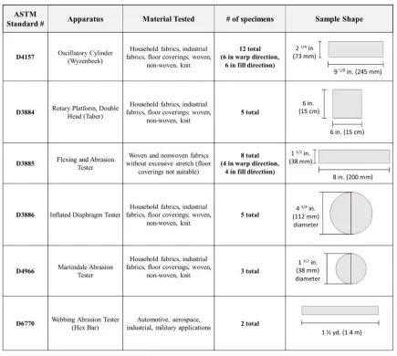
Table 3.1. Reference chart for common ASTM standard test methods used for evaluating textile abrasion resistance.
3.2.1 ASTM D4157– Oscillatory Cylinder Method
24
Figure 3.1. Wyzenbeek abrasion testing apparatus, side view.
Testing Apparatus
The Oscillatory Cylinder Abrasion Tester, or Wyzenbeek machine, is comprised of an oscillating cylinder equipped with clamps for mounting, four specimen holding arms, two
different calibrated masses, thumb screw, sponge rubber pressure pad, two slotted vacuum pipes, and an automatic cycle counter (Figure 3.1) [6]. The abradant sheet placed on the apparatus can be a cotton material, a two-piece laminated stainless steel wire mesh screen assembly, or grit sandpaper (which can also be used to refurbish the rubber pads). The most common head pressure used is 13.4 Newton (N) or 3 pounds of force (lbf) with 17.8 N or 4 lbf specimen tension, which would work for general to heavy duty upholstery end uses, but would not be suited for extremely abrasion resistant materials due to the time and energy needed to make any worthwhile abrasions; the caveat is that there would be little, if none at all, abrasions visible due to the relative low pressure on the material and abrasive aggressiveness of the available
25 Abrasive Mechanism
The abrasion occurs at the contact point where the sample is held taut in place while the specific abradant sheet fixed to the oscillating cylinder rubs back and forth. Abrasion intensity can be adjusted using sample tension, head weight, or abradant screen choice. Visually, abrasion shows as a linear area across the width of the material in the center of the sample, which can be seen in Figure 3.2.
Figure 3.2. Abraded area for samples tested with Wyzenbeek abrasion tester.
Testing Procedure
26 Testing Variables
A cycle is one motion back and forth against the sample, which is also called a “double rub”. The results are gathered in terms of abrasion to rupture ratio, percentage loss in breaking load, evaluation for visual changes in terms of either broken yarns/appearance of a hole or color change. Reporting the results depends on the test options used, the abradant used, tension, and load adjustment.
Apparatus Maintenance
Rubber pads should be changed at least once per year, while the cylinder section, steel screen, and vacuum system should be cleaned once per week. Calibration includes checking the tension with a digital force gauge, repositioning the bars as needed.
3.2.2 ASTM D3884 - Rotary Platform, Double Head Method
This testing method determines the abrasion resistance of textile fabrics using a rotary platform, double head (RPDH) tester, also known as the Taber® abraser (Figure 3.3) [4].
27 Testing Apparatus
The rotary platform, or most commonly the Taber® abraser (Figure 3.3) is comprised of a removable turntable platform with a rubber pad, clamp plate and knurled nut, and clamp ring to secure the specimen; pivoted arms that attach to the abrasive wheels and weights, platform rotating motor, vacuum nozzle and cleaner for debris removal, and revolution counter
[8]. Abrasion setup involves using specialized abradant wheels, Calibrade® Taber® abrading
wheels, with a specified weight up to 1000 grams. Calibrade® is composed of a non-resilient, vitrified binder and aluminum oxide or silicon carbide abrasive particles. Abradant wheels vary in abrasive texture, with applications ranging from abrading delicate textile fabrics to heavy duty automotive carpet materials. While the abradant wheels are more aggressive than the abradant fixed to the oscillating drum of the Wyzenbeek mentioned previously, the abrasive conditions for the Taber® are circular, relatively flat. Taber® Industries also manufactures some modifications on their original rotary platform design, one of relevance being the “linear abraser”. The Taber® linear abraser utilizes a free-floating head to follow the surface shape (flat, convex, or concave), and an adjustable stroke length of 0.2 inches to 4.0 inches with load weights up to 4050 grams [13]. Even so, this abrasion is only over a small area with the abrasions occurring in terms of inches per minute.
Abrasive Mechanism
28
Figure 3.4. Abraded area for samples tested with Taber® abraser.
Testing Procedure
Five specimens are cut in to approximately 6 in (15 cm) squares, then conditioned in standard atmosphere for testing textiles (70 ± 2°F or 21± 1 ºC, and 65 ± 2% relative humidity) (Table 3.1). Special care needs to be taken in avoiding any surface anomalies, such as folds, wrinkles, creases, oils, or water since contamination can alter the abrasive properties of the wheels or the material. After the specimens are mounted in the specimen holder, the abrading heads and vacuum head are lowered carefully onto the specimen, and then when turned on, the abrader runs for the specified number of cycles.
Testing Variables
29 of Organic Coatings by the Taber® Abraser), but would not be applicable in this case due the focus being on textiles [8].
Apparatus Maintenance
Care should be taken concerning equal spacing of the wheels, alignment of wheel bearings, proper platform positioning (no visible wobble), correct platform speed (72 ± 2 rotations per minute), good vacuum suction, and preparing the resilient abrading wheels for calibration. Resurfacing disks should be used prior to each new specimen, using 25 or 50 cycles depending on the duration of the previous specimen abrasion.
3.2.3 ASTM D3886 - Inflated Diaphragm Apparatus
This testing method determines the resistance to abrasion of woven or knitted textile fabrics, both conditioned and wet, using the, Inflated Diaphragm Abrasion Tester (Figure 3.5) [21].
Figure 3.5. Inflated Diaphragm Abrasion Tester diagram [19].
Testing Apparatus
30 a continuous changing abradant head or a static head, with air pressure set in the diaphragm to be 4 psi (28 kPa) with the load on the abradant set at 1 pound (454 grams).
Abrasive Mechanism
Abrasion occurs at the center of the sample mounted over the inflated diaphragm where the abradant rubs across back and forth. The abrasion direction can also be specified, with the ability to choose between standard multi-directional or uni-directional patterns depending on the engagement of the rotation mechanism. Visually, abrasions show in the center of the sample at the apex of the inflated area, in a linear pattern relative to the direction of the back and forth motion of the abradant.
Figure 3.6. Abraded area for samples tested with inflated diaphragm abrasion tester.
Testing Procedure
31 Testing Variables
Results are taken by pre-specified endpoint, which can be abrading material to failure, or abrading to a specific number of cycles and visually rating on a 1-5 scale. On the scale, 1 is a severe change in color with two or more broken threads and a 5 is essentially no change. For reporting, the abradant type must be specified, along with the abradant paper change frequency, air pressure and load on abradant plate, abrasion direction, cycles to endpoint or effect on visual properties, and any deviations from the standard test procedure.
Apparatus Maintenance
Calibration for the apparatus is more concerned with uniform inflation of the diaphragm in the sphere shape and driving mechanism of around 115 double strokes per minute [10]. This rate also rules out being comparable to the feet per minute of the hoist cable and would require an excessive amount of time and cycles completed, if able to show abrasion at all.
3.2.4 ASTM D4966 - Martindale Abrasion Tester Method
This method determines the abrasion resistance of all types of textiles fabrics with a pile depth of greater than 0.08 in (2 mm) by the Martindale abrasion tester (Figure 3.7) [22]. The Martindale is the most common method of testing abrasion resistance of textiles.
32 Testing Apparatus
The Martindale Abrasion Tester is comprised of standard abradant fabric and felt, polyurethane foam backing, fabric punches, and the machine to place the specimens. Issues other than surface abrasion are more likely to end in failure of the material, so material conditions also need to be considered. The assembled specimen holder on the machine should be set depending on the type of material being abraded, with apparel fabrics set to 1.31 ± 0.3 psi (9± 0.2 kPa) or for upholstery fabrics 1.74 ± 0.04 psi (12 ± 0.3 kPa), and a mounting weight of at least 2.5 ± 0.5 kg . The Martindale abrasion testing apparatus can be seen in Figure 3.7.
Abrasive Mechanism
Abrasion occurs at the interface of the sample and abradant material, with the sample being rubbed across the abradant face in a geometric pattern. Abrasion intensity can be adjusted by changing the abradant material type that the sample is rubbed across. Visually, the abrasions appear near the center of the sample, wearing in holes rather than in a linear pattern, usually at the center of the sample, which can be seen in Figure 3.8.
Figure 3.8. Abraded area for samples tested with Martindale abrasion tester.
Testing Procedure
33 insert and a polyurethane foam disk, then placed into assembled holders in the machine, before setting the counter and adding weight prior to turning machine on.
Testing Variables
Results are gathered in terms of either broken yarns/fabric hole or a change in shade being observed on the surface of the fabric. Reporting involves specifying the type of abradant, either the average number of rubs to failure or effect on physical qualities, and mass loss. Assessment of the abraded material includes examination at pre-specified intervals depending on the fabric characteristics, looking at broken threads, mass loss, or appearance changes [22].
Apparatus Maintenance
The abradant fabric should be changed for every new specimen, as well as at 50,000 rubs if fabric breakdown had not occurred at that point. The Martindale abrader is only strong enough to handle upholstery, so highly abrasion resistant materials would not be abraded as desired. Also, the rate and aggressiveness of the abrasion for the Martindale would require several changes of the abradant fabric and would give a circular wear.
3.2.5 ASTM D3885 - Flexing and Abrasion Method
34
Figure 3.9. Flexing and Abrasion Tester in the Wilson College of Textiles’ Physical Testing Laboratory at NC State University.
Testing Apparatus
The Flexing & Abrasion Tester is comprised of a balanced head and flex block assembly with two parallel plates connected with clamps, flexing bar yoke, thumb screw, micro switch stopping mechanism, cycle counter, two flex bars, calibration ribbon, and calibrated weights for tension and head weight [9]. Tension head weights are usually around 4 pounds, whereas the head weights are usually satisfactory around one pound. The Flexing and Abrasion Tester can be seen in Figure 3.9.
Abrasive Mechanism
35 webbing with breaking strength of up to 1000 lb. (4500 N) a mass of 2 lb. ± 2 oz (900 ± 60 grams) should be used, 4 lb. ± 2 oz (1800 ± 60 g) for breaking strength of 1000 to 3000 lb. (4500 to 13,500 N.), and 5.2 lb. ± 2 oz (2400 ± 60 g) for breaking strengths over 3000 lb. (13,500 N). A diagram of the area abraded using the Flexing and Abrasion tester can be seen in Figure 3.10.
Figure 3.10. Abraded area for samples tested with Flexing and Abrasion tester.
Testing Procedure
This test method is not applicable for materials that stretch excessively or floor coverings. Samples are cut into four warp and four fill directions specimens at least 200 mm (8 in) long and between 1 ¼ in (32 mm) and 1 ½ in (38 mm) wide depending on the number of yarns per 25 mm (Table 3.1). The specimens are then conditioned in standard atmosphere for testing textiles (70 ± 2°F or 21± 1 ºC, and 65 ± 2% relative humidity). After the specimen is clamped in and threaded through the flexing and abrasion apparatus, the head is released, and tension is applied before releasing the yoke is released and the counter is set before letting the machine pull back and forth.
Testing Variables
36 variation. Reporting involves relaying those gathered parameters for both the lengthwise and widthwise specimens, as well as the manufacturer and model of the test instrument.
Apparatus Maintenance
Calibration is performed with special ribbon made of fused acetate, about 1 inch wide, provided by the abrader manufacturer, placed on the apparatus in the same way as a specimen. Visually, the abrasions show as imperfections or broken yarns at the center of the sample nearest to the flex point. Calibration wise the test machine needs to be on a vibration free, level surface, and the hexagonal rods need to be maintained, kept free of any imperfections, with a cold drawn finish and a Rockwell Hardness of B-91 or B-101.
3.2.6 ASTM D6770 - Hex Bar Method
This testing method determines the abrasion resistance using a hex bar abrasion tester for textile webbing (Figure 3.11) [24]. This method is similar to the flexing and abrasion tester in terms of concept, but the tested material is far more rugged. Generally tough materials used for automotive or industrial applications are specifically selected for this test.
37 Testing Apparatus
The hex-bar abrasion tester, or Webbing abrasion tester, is comprised of a standard hex bar attached to a machine capable of reciprocating motion with the sample. The sample is attached to the reciprocating mechanism at both ends, with the center passing across the hex bar and tension set. A drum moves the specimen across the hex bar and can have weights attached, which can be seen in Figure 3.11.
Abrasive Mechanism
Abrasion occurs at the point where the sample rubs back and forth while being pulled across the hexagonal steel rod. Abrasion intensity can be adjusted by changing accessory weights/buckles. Visually, abrasions show at the center of the sample length, near the hex bar area. The Hex Bar abrasion tester is comprised of a mechanism for reciprocating motion of the webbing over a fixed, standardized hex bar [12]. One specialized type of hex bar tester can be seen in Figure 3.11, which is used for testing the abrasion resistance of seatbelt straps. The Webbing abrasion tester shows abrasions in the middle section of the sample, around twelve inches across the entire width of the material (Figure 3.12).
38 Testing Procedure
Two specimens are cut to 1.4 meters (1.5 yard) in length, one marked “A” for abraded and the other marked “U” for unabraded before being conditioned in standard atmosphere for testing textiles (70 ± 2 ºF or 21± 1 ºC, and 65 ± 2% relative humidity) (Table 3.1). The specimens are mounted with the required mass attached to a drum, then oscillate across a hexagon rod across around 300 mm (12 in) at the rate of around one stroke per second for 5000 strokes.
Testing Variables
Results are gathered in terms of average breaking force for both the abraded and
unabraded specimens, as well as the retained breaking force to the nearest one percent, which is then placed in the report. Also, the specimens evaluated are longer in length, like a seatbelt strap, and would not be representative of the smaller surface area exposed to the longer linear abradant.
Apparatus Maintenance
The hexagonal rods need to be recertified if any burrs, nicks, or scales form. The surface where the apparatus is located must also be free from vibrations as that can alter the results. 3.2.7 Modified Abrasion Test Methods
39 conditions and actual applicable conditions [25], [26]. In these unique cases, a modified version of standard test methods could be used, or a completely new method could be developed with respect to those specific conditions incurred. This section will examine three instances of new test methods being implemented for more realistic reporting of material degradation.
One set of researchers modified standard testing methods to compensate for the
differences in abrasion resistance of leather motorcycle protective clothing in laboratory testing and data from actual motorcycle crashes [27]. Bolschweiler was concerned with finding a reliable method to examine materials used to produce motorcycle protective clothing after noticing discrepancies between the values for abrasion resistance found using the Taber® data compared to the actual conditions experienced during motorcycle crashes. The data for abrasion resistance of the materials tested were found in other research using the Taber® abraser, which did not provide an accurate representation of the types of abrasion actually experienced during motorcycle crashes. After development, Bolschweiler discovered that using a lawn edge stone to produce the abrasions provided a much more accurate representation in terms of visual
comparison and reported cycles to failure, though the direction of the abrasion was circular instead of linear due to the machine used. The alignment of accurate abrasion mechanism representation and repeatable testing method provided valuable information in terms of actual material behavior for the leather motorcycle protective clothing, resulting in the development of better protective clothing in the future.
40 mimic the abrasive action seen by a transmission belt drive, with specific focus on providing visually similar abrasions for the materials. The simulated transmission belt drive set up
provided a material failure point time that was much closer to the time observed in the engine as opposed to using other standard testing methods just for a trivial data benchmark.
An additional alternative testing method involves simulating the abrasive action between layers of material and a nonwoven interlining [10]. Instead of using subjective measurements for material hand which was standard in the industry at the time, Kalebek used a proprietary
apparatus in combination with the standardized test method for the Martindale abrader to test both the frictional behavior and the abrasion resistance. Using the proprietary apparatus allowed material properties to be seen that would have otherwise not been apparent with the subjective measurements or the Martindale abrader alone.
Lastly in a study on the abrasion resistance of socks and hosiery, Gupta challenged the available abrasion testing techniques, concluding that while one could use a Taber® abraser to abrade the hosiery, the effect would not mimic actual wear [28]. Abrasion occurs in hosiery between layers of material, which was not accurately represented by the coarse abrasive
Calibrade ™ wheels of the Taber® abraser. Utilizing new ideas and techniques in combination with the test standard methodology allows creative exploration of solutions for the accurate representation of real-world abrasive conditions.
3.2.8 Understanding the Testing Approach—Standard versus Modified
41 Martindale both require circular sample shapes, though the sample and abradant motion for each are in opposition. The Taber® is the only square shape, despite the mounting similarity of the inflated diaphragm tester. Several are concerned with statistical analysis of the results to understand the material strength after abrasion, whereas others are only concerned with the amount of abrasions that the material can take before it fails, either by the breaking of yarns or a complete hole in the material. In the standard test method for Taber® abrasion, ASTM mentions that “while ‘abrasion resistance’ (often stated in terms of the number of abrasion cycles) and ‘durability’ are frequently related, the relationship varies with different end uses and different factors may be necessary in any calculation of predicted durability from specific abrasion data” [4]. An important notion emerges from these experiences: testing without consideration for conditions experienced could only produce data for the sake of producing data—potentially providing a numerical benchmark for the material behavior, but not anything that would show how the material would react in a real-world situation. Alternatively, combining a representative scenario with a repeatable method can provide information about a material that could lead to better informed design decisions and products overall.
The purpose of this review was to examine existing abrasion testing methods to understand the similarities and differences between processes, as well as the strengths and weaknesses of each technique. The most prominent difference between all these testing methods is the mechanism of abrasion, each having a relatively practical inspiration that was converted into a replicable method to relate application and use.
Advancing technology and newer material resources will continue to provide new situations and conditions that should be considered during textile production and
42 invaluable when developing protective textiles. The conscious link of the simulated abrasive mechanism with real conditions will provide data that is useful for application/end-use going beyond theoretical application.
3.3 Cable Abrader Apparatus Overview
The cable abrader is a newly developed testing apparatus that utilizes stainless-steel cable rope and brake tension to simulate the abrasive conditions created by a helicopter rescue hoist cable. The cable abrader is comprised of three main components: the simulated helicopter hoist system, the adjustable sample mount, and the attached monitoring software. Abrasion occurs when the sample mount is pressed to the tensioned hoist cable while it moves across the surface of the sample.
43 with the stainless-steel wire rope cable abradant produces a distinct concentrated linear pattern on the sample tested and provides potential for realistically mimicking the abrasive conditions incurred by a rescue helicopter hoist cable. With a developed testing method using the cable abrader, results could represent the real-life conditions experienced and allow for appropriate application-based material comparisons.
44
Figure 3.14. Sample mount (shown in red) detail diagram: left showing face of sample mount, and right showing sample mount on cable at tension.
3.4 SuperFabric™
SuperFabric™ is a material manufactured by Higher Dimension Materials (HDM of Minneapolis, MN). SuperFabric™ is highly durable and abrasion resistant with many different applications from sport apparel to industrial automotive components. The material is composed of a fabric that is overlaid with tiny dots (also known as the “guard plate”) which can come in various thicknesses and geometries for different applications. The SuperFabric™ guard plate works by providing protection to the surface of the material via the hard dots, while still allowing material flexibility since the dots move along with the fabric. Figure 3.15 shows the side view of the SuperFabric™ material’s flexibility in the diagram, with the dots not stifling material
45
Figure 3.15. SuperFabric™ side view showing material flexibility and protective coverage by
the guard plate [48].
46 CHAPTER 4 . LINEAR CONCENTRATED ABRASION TEST METHOD
DEVELOPMET WITH CABLE ABRADER APPARATUS
4.1 Introduction and Background
The cable abrader is a new abrasion testing apparatus developed to mimic the abrasive conditions produced by helicopter rescue operations on a hoist operator’s protective glove. Currently there is no other abrasion testing machine capable of accurately representing the linear concentrated abrasion pattern caused by the stainless-steel cable rope of the helicopter hoist. An understanding of the real-life abrasive conditions is essential to providing useful results in terms of realistic material longevity and behavior. Consequently, assessing rescue hoist glove abrasion resistance requires an understanding of the abrasive interaction between the protective glove and the hoist cable. The chosen method needs to simulate the specific abrasive action incurred from a hoist glove being pressed against an actively moving helicopter hoist cable back and forth. To accurately represent the abrasive mechanism, the technique must have an appropriate abrasion pattern, intensity, and concentration. Part of developing the test method for the cable abrader studied well defined ASTM abrasion test standard methods to see what components of each would be useful and applicable. From there, the different sources of data needed to be explored for relevancy, and running conditions needed to be optimized. With those conditions met, a well-rounded testing approach can be attained for using the cable abrader.
4.1.1 Cable Abrader Apparatus
47 stainless-steel cable is 3/16 inches (4.76 mm) thick, with an inner core wrapped clockwise and the outer threads wound counterclockwise. The sample is attached to the sample holder which is connected to the sample mount, and can be adjusted using one of two rail actuators; one actuator rail moves the sample towards or away from the cable, and the other actuator rail moves the sample mount between two set stops on either side of the cable to compensate for the rolling motion the cable undergoes due to the construction of the wire rope. Several components of the cable abrader are fully adjustable, including the speed dial and brake tension. Switches are also employed for other modes needing adjustment, active options including the power switch (on/off modes), the brake power switch (on/off modes), the brake selection (cable up/neutral/cable down modes), with an inactive mode for water control for future machine iterations. The image in Figure 4.1shows the cable abrader apparatus with the sample mount area enclosed, as it would be during the actual cable run portion of sample processing. The main components of the cable abrader can also be seen in Figure 4.1, with the laptop computer sitting on top of the protective case for the apparatus, the sample mount and load cell visible inside the front of the enclosed area, and the cable reels and brake gears in the center of the apparatus.
48 4.1.1.1 Simulated Helicopter Hoist System
To mimic the conditions incurred by the helicopter hoist cable an identical cable has been mounted in the bidirectional reel system. The cable is 3/16-inch stainless steel wire rope, with a usable length of approximately 250 feet. Cable length on the cable abrader is comparable to that used in actual helicopter hoists, with common rescue helicopters using cable between 200 and 250 feet long [42]. An adjustable set of brake and speed controls set the cable speed, with a speed setting of 6 generally showing to be around 93-98 feet per minute average over the course of a cable run. The brake system is manually switched between gears, with the active direction having the desired gear locked in (Figure 4.2).
Figure 4.2. Cable Abrader manual gear shown from the top, with gear for “Cable Down”
49 The cable runs between two reels through a series of wheels to help keep tension, each direction run serving as a simulation for either cable being deployed or retracted into the hoist. Figure 4.3 shows the “Cable Up” configuration, with the cable passing from the front reel through a series of wheels before passing upwards over the sample mount to mimic the helicopter hoist cable retracting into the hoist drum. Figure 4.3 shows the “Cable Down” configuration, with the cable passing from the back reel through a set of wheels then down vertically across the sample mount to mimic the helicopter hoist cable deploying down to the scene.
Figure 4.3. Cable abrader diagram, “Cable Up” configuration, front reel loaded with cable,
50
Figure 4.4. Cable abrader diagram, “Cable Down” configuration, back reel loaded with cable,
cable direction passing down vertically across the sample mount and wrapping around the front reel.
4.1.1.2 Sample Mount
51
Figure 4.5. Side view of sample mount area. White arrow shows the sample mount track projection, while the black arrow shows the path of the sample into the cable at tension. Cable location accented in green dashed line to indicate cable location.
The sample holder is comprised of a metal frame filled with ballistic grade silicone, welded to a bolt that screws directly to the load cell. The ballistic grade silicone was chosen for the cable abrader sample mount due to the durability of the material, as well as the similarity to the hardness of a tensed hand muscle. The sample holder currently being used has red silicone with a hardness of 60 Shore A, which is a medium hardness equivalent to the rubber for windshield wipers [43]. There are additional sample mounts that can be equipped on the machine if desired, one with 30 Shore A hardness and one with embedded thermistors. Due to the apparatus being very new, the decision was made to utilize the hardest silicone since it was potentially the most durable in case of unexpected material break through (a hole in the
material), reducing the risk of damaging equipment. As the samples being tested did not produce noticeable frictional heat, the thermistor sample holder was not equipped.
52 are held to the mount using a set of small hook-and-loop straps that hook on the same bolts as the side clamps. With the clamps and straps equipped, the sample was held as close to flat as
possible to the silicone surface of the sample mount (Figure 3.5).
Figure 4.6. Sample mount disconnected from load cell showing red silicone component used for indicator (left), and hook and loop straps used to secure the sample top and bottom to the sample mount area (right).
53 4.1.1.3 Software Monitoring
Sensors connected from the sample mount area to the load cell, which then send data to the on-board computer system and connected software. For use without the thermistors, the only aspect that was monitored was the sample pressure. The sample pressure is reflected in foot-pounds of torque due to the unique double coiled construction of the attached stainless-steel cable rope. Connection to the load cell and sample mount output the sample pressure via


![Figure 2.5. Flame resistant flight suit worn by helicopter aircrew [32].](https://thumb-us.123doks.com/thumbv2/123dok_us/1549135.1190106/23.612.244.366.375.592/figure-flame-resistant-flight-suit-worn-helicopter-aircrew.webp)