Design Optimization of Stabilizer Bar Link
Used In Sedan Vehicles
Farhan E M
1, Dr.S.Sankar
2, Tedy Thomas
3, Deepak.V.K
4PG Student, Dept. of Mechanical Engineering, Nehru College Of Engineering and Research Centre, Thrissur, Kerala,India1
HOD, Dept. of Mechanical Engineering, Nehru college of engineering and Research Centre,Thrissur,Kerala,India2 Assistant Professor, Dept. of Mechanical Engineering, Nehru college of engineering and Research Centre, Thrissur,
Kerala, India3
Assistant Professor, Dept. of Mechanical Engineering, Nehru college of engineering and Research Centre, Thrissur, Kerala, India4
ABSTRACT: Suspension is the system of tyres, springs, shock absorbers and linkages that connects a vehicle to its wheels and allows relative motion between the two. Suspension systems must support road holding, handling and ride quality, which are at odds with each other. Normally the ball joints on stabilizer bar link at either end deteriorate and develop lost movement which can be heard as a rattling or knocking noise. If this is ignored and the link rod actually breaks, the anti-roll bar becomes completely ineffective. In this project, an existing model of stabilizer bar link is designed in SolidWorks 2016 Edition, and analyzed the same in Ansys15.0.Then two modified designs are modeled with change in shape of the link rod and introduction of spring in ball joint housing.Modified designs are analysed and compared with the existing design.Three different materials such as Stainless steel, Titanium alloy and Grey cast iron has been analysed in order to find out the best suitable material for the stabilizer bar link.A suspension system is also designed according to the specification of an common sedan car,where the existing and modified stabilizer bar link is installed to and analysed.Static structural and modal analysis are done on the designed models and results are compared. From the results it can be concluded that spring introduced stabilizer bar link applied with stainless steel is the best choice for application in the ssuspension system of sedan vehicles.
KEYWORDS: Stabilizer bar link,Sway bar link, Balljoint,Titaniumalloy,Stainlesssteel,Grey cast iron I. INTRODUCTION
to lean excessively in turns and feel less stable and secure on the road. A worn-out sway bar link must be replaced to keep your vehicle safe.
II. DESIGNPROCEDURE
This
section deals with the process of modeling. Model is a representation of an object, a system, or an idea in some form other than that of the entity itself. Modeling is the process of producing a model; a model is a representation of the construction and working of some system of interest. A model is similar to but simpler than the system it represents. Generally, a model intended for a simulation study is a mathematical model developed with the help of simulation software. Softwares commonly used for modelling are SolidWorks, Creo, Catia, Unigraphics etc. In this project SolidWorks 2016 edition is used for the modelling process.Design of stabilizer bar link
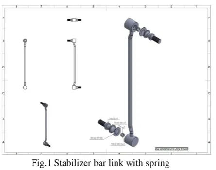
Table 1 Dimensions of stabilizer bar link with spring
Fig.1 Stabilizer bar link with spring
Design of suspension system Table 2 Dimensions of suspension system
Fig.2 Suspension system
S.no Description Dimensions(mm)
1 Length of the spring 254
2 Radius of the spring wire
5
3 Total length of system 479
4 Radius of the flange 69
5 Thickness of the flange 2
S.no Description Dimensions(mm)
1 Length of the rod 230
2 Radius of the ball bearing
8
3 Radius of the flange 7
4 Length of the screw 21
5 Radius of the screw 4.25
6 Angle of the bend 200
7 Length of the spring 5
III.ANSYSPROCEDURE
This section deals with the analysis of the designed model. The model that is in STEP format is analysed. Static structural analysis of both stabilizer bar link and suspension system is performed by applying the working load and number of supports used is two. The model is imported to Ansys and meshing is performed. The mesh size used is 4.4 mm. From the results obtained optimal design is selected. Suitable materials are applied to three different models of stabilizer bar link and modal analysis is performed. Different softwares such as Comsol, Radioss solver, Abaqus, Hypermesh, Ansys etc. are used for analysis. In this project Ansys R15.0 is used for design analysis.
Design analysis
The figure shown below represents the meshed image of total suspension system and the force application in the stabilizer bar link
Fig.3 Meshed image of total suspension system Fig.4 Force application in stabilizer bar link The figure shown below represents the total deformation in the stabilizer bar link with spring
Table 3 Overview of analysis results
Fig.5.Total deformation of stabilizer bar link with spring
Sl.No Stabilizer bar link
Total deformation(mm)
Max
1 Ordinary 12.388
2 With change in
shape 8.3413
From the analysis results it can be concluded that the stabilizer with introduction of spring have the least value of maximum total deformation. Hence stabilizer bar link with spring is selected for further analyses.The figure shown below represents the total deformation of suspension system with spring introduced stabilizer bar link
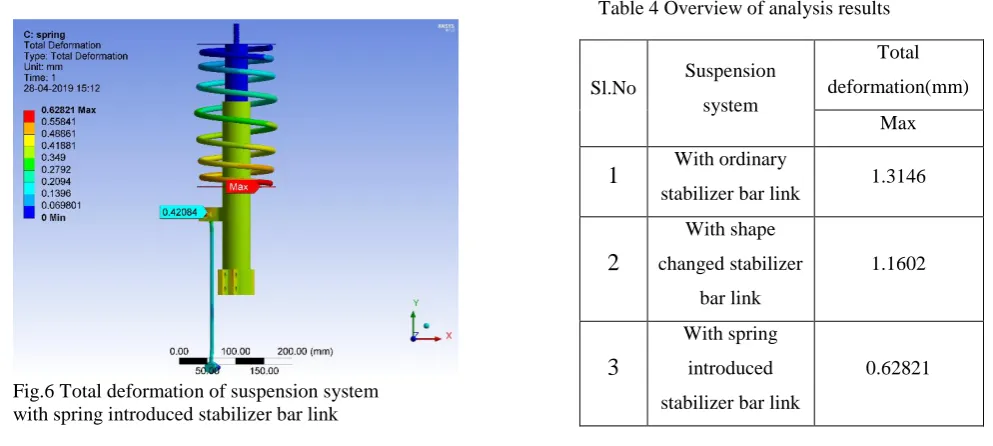
Table 4 Overview of analysis results
Fig.6 Total deformation of suspension system with spring introduced stabilizer bar link
From the analysis results it can be concluded that the suspension system with spring introduced stabilizer bar link have the least value of maximum total deformation. Hence suspension system with spring introduced stabilizer bar link is selected as the best suitable system.
IV.MATERIAL OPTIMISATION
Table 5 Overview of analysis results of the stabilizer bar link using three different materials Sl.No Suspension
system
Total deformation(mm)
Max
1
With ordinarystabilizer bar link 1.3146
2
With shape changed stabilizer bar link 1.16023
With spring introduced stabilizer bar link0.62821
Design parameter Stainle ss steel Titaniu m Alloy Grey cast iron Total deformation (mm)
Max 3.897 5.7353 5.0527
Min 0 0 0
Directional deformation
(mm)
Max 3.5731 5.1838 4.5908
Min -0.0316
93
-0.02174 -0.020947
Equivalent stress (MPa)
Max 309.75 589.98 541.49
Min 0.0025 005
0.00477
71 0.0040365
Equivalent elastic strain
Max 0.0016 135
0.00489
22 0.0043833
Min 3.1246 e-8
6.8763e
The above shown table represents analysis results of the stabilizer bar link using three different materials.Three different materials are applied to the stabilizer bar link with spring and the analysis results are compared to select the most suitablematerial. The three different materials used for analyses are Stainless Steel, Titanium Alloy, Grey Cast Iron.
V. MODALANALYSIS
Table 6 Comparison of the natural frequencies of the Table 7 Comparison of the natural frequencies of three different models of stabilizer bar link stabilizer bar link applied with different materials
By comparing the results of modal analysis listed in the Table 6 and 7,it can be clearly understood that the spring introduced stabilizer bar link applied with stainless steel is the best suitable for the suspension system.
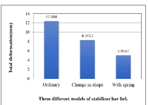
VI.RESULTANDDISCUSSION
Fig. 7 Total deformation of three different models of stabilizer bar link Sl.No Mode Ordinary
Change in shape
With spring
1
1 22.082 25.32 30.066
2 2 24.047 25.681 31.487
3 3 247.3 250.93 240.77
4 4 253.13 256.91 241.26
5 5 344.15 311.87 350.93
6 6 466.47 460.54 508.87
Sl.No Mode Stainless Steel
Titanium Alloy
Grey Cast Iron
1 1 34.515 32.236 30.066
2 2 34.69 34.225 31.487
3 3 278.97 271.26 240.77
4 4 280.74 275.04 241.26
5 5 423.55 363.62 350.93
From the above graph,we can see that the total deformation has reduced by 32.67% when the shape of the stabilizer bar link was changed compared to the ordinary shape.We can also see that the total deformation has reduced by 59.21% when a spring is introduced in the ball bearing housing compared to the ordinary one.
Fig 8 Comparison of spring introduced stabilizer bar link applied with three different materials.
From the above graph,we can see that the total deformation of the stabilizer bar linkhas reduced by 11.90% when it is applied with Grey cast iron compared to Titanium alloy.We can also see that the total deformation has reduced by 32.05% when it is applied with Stainless steel compared to Titanium alloy.
VIICONCLUSION
In this project three different models of stabilizer bar link were designed using SolidWorks 2016 edition and the designed model was analysed using ANSYS R15.0. From the analysis results it was found out that stabilizer bar link with spring introduced in the ball bearing housing has minimum total deformation. Then a suspension system was designed according to the specification of a common sedan vehicle and was subjected to a force of 500N and it is here where the stabilizer bar link acts. After analysis it is found that the suspension system with spring introduced stabilizer bar link has the least total deformation. From the three different materials such as Stainless Steel, Titanium alloy and Grey cast iron applied, analysis results shows that the stabilizer bar link applied with Stainless steel provides least total deformation. Results on modal analysis show that stabilizer bar link with spring exhibits higher natural frequency. Modal analysis on spring introduced stabilizer bar link with three different materials such as Stainless steel, titanium alloy and Grey cast iron also proves that Stainless steel have higher natural frequency. From above results we can conclude that spring introduced stabilizer bar link applied with Stainless steel proves to be the best choice for improved performance in sedan vehicles.
3.897
5.7353 5.0527
0 1 2 3 4 5 6 7
Max
Total deformation (mm)
STAINLESS STEEL
TITANIUM ALLOY
REFERENCES
[1] E.A. Ossa, C.C. Palacio, M.A. Paniagua,Failure analysis of a car suspension system ball joint, Materials Engineering Research Group, Eafit University, Cra. 49 No. 7 sur 50, Medellin, Colombia
[2] AnshulDhakar and RishavRanjan, Force calculation in upright of a formula sae race car, Department of Mechanical Engineering, RV College of Engineering,
[3] SadjyotBiswal,AravindPrasanth, Dr. R Udayakumar, Shobhit Deva, AmanGupta,Design of a suspension system and determining suspension parametersof a medium downforce small Formula type car.Automotive, Mechanical Department, BITS Pilani Dubai Campus, DIAC, 345055
[4] C. Kavitha , S. Abinav Shankar , B. Ashok Adaptive Suspension Strategy For A Double Wishbone Suspension Through Camber And Toe Optimization .A. Criminisi, P. Perez, and K. Toyama, “Region filling and object removal by exemplar-based image inpainting.”, IEEE Transactions on Image Processing, vol. 13, no.9, pp. 1200– 1212, 2004.