1
1
Orientating the future bio-macromolecular electron microscopy
2
Fei Sun 1,2,3
3
1 Center for biological imaging, Institute of Biophysics, Chinese Academy of Sciences;
4
2 Center for Excellent, National Laboratory of Biomacromolecule, Institute of Biophysics, Chinese
5
Academy of Sciences; Datun Road 15, Chaoyang District, Beijing 100101, China. 6
3 School of Life Science, University of Chinese Academy of Sciences.
7
Email: [email protected] 8
9
ABSTRACT
1
With forty years of developments, bio-macromolecule cryo-electron microscopy has met its 2
revolution of resolution and is playing a very important role in structural biology study. According 3
to different specimen states, cryo-electron microscopy (cryo-EM) involves three specific techniques, 4
single particle analysis (SPA), electron tomography and sub-tomogram averaging, and electron 5
diffraction. All these three techniques have not realized their full potentials of solving structures of 6
bio-macromolecules and therefore need to be developed in the future. In this review, the current 7
existing bottlenecks of cryo-EM SPA are discussed with theoretical analysis, which includes air-8
water interface during specimen cryo-vitrification, bio-macromolecular conformational 9
heterogeneity, focus gradient within thick specimen, and electron radiation damage. Besides, 10
potential solutions of these bottlenecks are proposed and discussed, which are worthy of further 11
investigations in the future. 12
KEYWORDS
13
Cryo-electron microscopy; Air-water interface; Conformational heterogeneity; Focus gradient; 14
Radiation damage. 15
16
PACS: 36.20.-r, 68.37.Og, 87.64.Ee, 87.80.-y
17
18
19
1. Introduction
1
Revealing the detailed 3D structure of bio-macromolecules is one of the important steps to 2
understand the life. In recent years, cryo-electron microscopy (cryo-EM) has completed its 3
revolution and been becoming one of the major biophysical techniques to study the 3D structures 4
of bio-macromolecules, especially of membrane protein complexes and supra macromolecular 5
assemblies, giving a big impact on our understanding of the life. 6
The development of cryo-EM technology started from the last century in 1970~1980s when the 7
significant electron radiation damage of biological specimen was discovered and the low-dose 8
illumination technique was proposed [1, 2], the cryo-vitrification method to fix the native structure 9
of biological specimen was established [3, 4], and the image analysis theory to process the low 10
signal-to-noise-ratio (SNR) low-dose cryo-EM micrographs of bio-macromolecules was developed 11
[5]. The potential of electron microscopy to determine the high resolution structure of bio-12
macromolecules had been revealed by the 3D structure of purple membrane in 1975 [6] and 13
seriously discussed with a theoretical consideration in 1995 [7]. In recent years, with the 14
instrumental advances in electron optics and improved stabilities of electron microscopes, the 15
development of sophisticated image processing software [8-10] and the automation of data 16
collection [11-13], the improvement of phase plate technology [14, 15], especially the success of 17
the direct electron detector [16-18], cryo-EM technology has reached its revolution in resolution 18
[19] with the milestone work that the structure of transient receptor potential cation channel TRPV1 19
was determined to 3.4 angstrom in 2013 [17] and the structure of the glutamate dehydrogenase 20
macromolecular structures, e.g. spliceosome [21], photosynthetic complex [22], and mitochondrial 1
respiratory complex [23], have been solved to near atomic level, which could not be achieved by 2
using traditional structural biology approaches. 3
According to the states of the biological specimen and the experimental workflow, cryo-EM 4
technologies can be classified into three different techniques, cryo-EM single particle analysis (SPA), 5
cryo-electron tomography (cryo-ET) and sub-tomogram analysis (STA), and cryo-electron 6
diffraction (cryo-ED). Cryo-EM SPA is used to analyze the 3D structure of purified bio-7
macromolecules in solution, which are vitrified into a thin ice layer. Ten of thousands of cryo-8
EM images of the bio-macromolecule are needed to increase SNR and reconstruct a high resolution 9
structure [24]. Cryo-ET can reconstruct the native 3D structure of a local region within a cell or 10
tissue and the in situ structure of bio-macromolecules can be further analyzed by STA [25]. There 11
is no need to purify bio-macromolecules from cell or tissue while hundreds of tomograms of cryo-12
lamella of cell or tissue are needed to obtain a high resolution in situ structure of bio-13
macromolecules. Cryo-ED is a kind of technique to use cryo-electron microscope to analyze the 14
crystallized biological specimen. It collects the electron diffraction data from 2D crystals or 3D 15
nano-crystals of bio-macromolecules and then solves the high resolution structures using 16
crystallographic theories, where the technique to study 2D crystals was used to be called electron 17
crystallography [26] and the one to study 3D nano-crystals emerged recently and called as micro-18
electron diffraction [27] 19
Cryo-EM SPA has been developed mature enough in past decades and been becoming the major 20
given to Jacques Dubochet, Joachim Frank and Richard Henderson for their great dedicative work 1
in developing cryo-EM SPA technique. Cryo-ET STA has been developed quickly in recent years 2
and will become an important as well as a unique approach to study the in situ structure of bio-3
macromolecules in the future. In this paper, I will discuss the current bottlenecks of cryo-EM SPA 4
and present some potential solutions in my personal view. 5
2. Current technical bottlenecks in cryo-EM SPA
6
There have been many good reviews to describe the technique of cryo-EM SPA including the 7
theory, workflow, image processing and applications [28-30]. In brief, cryo-EM SPA starts from the 8
cryo-vitrification of bio-macromolecular solution and needs to collect thousands of high quality 9
cryo-EM micrographs in a high-throughput way with a limited illumination dose (20 ~ 60 e/Å2
10
normally), a defined magnification yielding a proper pixel size (0.8 ~ 1.5 Å/pixel normally), and a 11
proper defocus range (0.8 ~ 3.0 µm). The subsequent image processing includes micrograph 12
correction (motion and distortion correction, dose weighting) and evaluation, contrast transfer 13
function estimation, particle picking and sorting, 2D and 3D classification, orientation refinement 14
and reconstruction, and post-processing (map sharpening). Since the limited illumination dose 15
yields a very noisy raw image of bio-macromolecules that are embedded in vitreous ice, ten 16
thousands of particle images are needed to increase SNR. Thus, the basic assumption behind cryo-17
EM SPA is that all the analyzed bio-macromolecules should have an identical structure and 18
conformation, which is actually not always true. 19
Starting from 2013 when the near atomic structure of TRPV1 was first solved [17], the number 20
already 5541 cryo-EM maps deposited in electron microscopy database (EMDB, 1
http://www.ebi.ac.uk/pdbe/emdb) [31] while there are only 1566 entries in 2012. Most of the 2
deposited maps were obtained by cryo-EM SPA. However, only a small portion of the map 3
(313/5541) can reach a resolution higher than 4 Å and only a few structures can be solved to the 4
resolution higher than 3 Å (Figure 1), which actually forms a barrier for cryo-EM SPA to be widely 5
applied into pharmaceutical industry. 6
Several bottlenecks are still there in cryo-EM SPA from sample preparation, data collection to 7
image processing, which forms the barrier to reach a better resolution. In cryo-vitrification during 8
sample preparation, the existence of air-water interface increases the possibility of disassociation 9
and denature of bio-macromolecules, which prohibited many fragile macromolecular complexes to 10
be studied by cryo-EM SPA. The existence of intrinsic conformational flexibility of bio-11
macromolecules rules out the basic assumption upon the identical structure and conformation in 12
cryo-EM SPA, which has been restricting to approach high resolution. During cryo-EM imaging, 13
the SNR from the current instrument and hardware is still not enough to study the high resolution 14
3D structures of bio-macromolecules when their molecular weight is smaller than 60 kDa. The phase 15
plate and direct dection detector technologies can be improved better to increase the current cryo-16
EM SNR. The cryo-electron microscope can be made more stable, easy to use and dedicative for 17
the cryo-EM SPA workflow with much improved throughput. When the size of bio-macromolecule 18
becomes large or the thickness of biological material increases, the existence of the Ewald sphere 19
effect and focus gradient will limit the approachable resolution of cryo-EM imaging in the current 20
procedures. The ultimate bottleneck of cryo-EM SPA is the physical nature of radiation damage of 1
bio-macromolecules during cryo-EM imaging, which can not be avoided and is the key limitation 2
of achieving atomic resolution in cryo-EM SPA. 3
Glaeser has made a very good discussion of the above bottlenecks and given thoughtful 4
perspectives [32]. Here, I would like to focus on cryo-vitrification, conformational heterogeneity, 5
thick sample, and electron radiation damage, further discuss these limitations in theory, and propose 6
new solutions to solve these bottlenecks. 7
2.1 Cryo-vitrification and air-water interface
8
The current cryo-vitrification method was originally invented by Dubochet’s group in 1984 [3], 9
which is called plunge freezing. The EM grid coated with a carbon supporting film is pre-treated 10
with plasma cleaner and then nipped by a fine tweezer and mounted onto the plunge freezer. 3~5 µl 11
bio-macromolecule solution is dropped onto the supporting film. After a few seconds of incubation, 12
most of the liquid is blotted with filter paper, leaving a thin layer of the solution (30 ~ 50 nm 13
thickness) on the grid. Subsequently, the grid is then quickly plunged into liquid ethane that is pre-14
cooled by liquid nitrogen, resulting the vitrification of the thin solution layer. Finally, the bio-15
macromolecules are embedded in the vitreous ice with their native structure preserved. The 16
procedure of this cryo-vitrification method did not change much since its invention and is still now 17
widely used in the world for cryo-EM SPA. Several venders made commercialized instruments 18
(Thermo Fisher Vitrobot, Leica EM GP and Gatan CP3) for cryo-vitrification, which increase the 19
throughput and reproducibility by controlling experimental parameters (e.g. humidity, temperature, 20
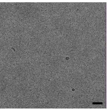
However, more and more labs found that the homogeneity of the bio-macromolecule became 1
significantly decreased from cryo-vitrified sample when compared with the negatively stained 2
sample. The worst case is that although the specimen shows even distribution with homogenous size 3
and shape from the negative stain electron micrographs, few particles could be identified/recognized 4
from the cryo-EM micrographs (Figure 2A). The reason of this phenomena has been fully discussed 5
by Glaeser and colleagues [33, 34] and now widely recognized to be the effect from the air-water 6
interface (Figure 2B). 7
During plunge freezing, the thin solution layer after filter paper blotting results a very large 8
surface-to-volume ratio (~ 20 um-1) in comparison with its original value of (~ 2.0 e-3 um-1). Thus
9
the bio-macromolecule in the thin layer of the solution has large opportunity to reach the surface, 10
which has been observed from the recent Cryo-ET study that ~ 90% of particles were absorbed to 11
the air-water interface [35]. The movement of the bio-macromolecule
√
follows the Brownian 12motion law according to the following equation, 13
=
(1) 14where, is the time of the motion, is the radius of the bio-macromolecule, is the coefficient 15
of viscosity of the solution (for water at 10
℃
, it is 1.308 mPa.s), is the Boltzmann constant, 16and is the temperature in Kalvin. For the thickness of 50 nm of the layer and a 20 nm diameter 17
of the bio-macromolecule, the averaged time (at = 283 K) for the bio-macromolecule reaching 18
the surface can be estimated as ~ 20 ms. The time can be even shorter (~ 6 ms) for a thinner ice (40 19
the thin layer of the solution, the bio-macromolecules can quickly approach the surface called the 1
air-water interface, which has the large possibility to induce denaturation of the bio-macromolecule 2
[34]. The thermodynamics of this procedure can be further described as below (Figure 2B), 3
(2) 4
where represents the concentration of bio-macromolecule in the solution, represents the 5
concentration of bio-macromolecule bound to the air water interface, and represents the 6
concentration of denatured bio-macromolecule. Thus, the speed of bio-macromolecule denaturation 7
is determined by the reaction constants , , and . The molecular dynamics simulation to 8
study the absorption behavior of lysozyme onto the hydrophobic surface of graphite suggested that 9
the secondary structures of lysozyme disappear at 10 ns after bound to the surface [36]. Thus, the 10
order of can be estimated of 1 × 10 ~ 1 × 10 , the denaturation of the bio-11
macromolecule can occur less than 1 μs. 12
During plunge freezing, the time normally takes seconds from the completion of blotting to 13
plunging into liquid ethane, which are much longer than the one for bio-macromolecules 14
approaching to the air-water interface and denatured. Therefore, it can be explained why it was 15
difficult to obtain good cryo-EM micrographs for those fragile bio-macromolecules that are easily 16
denatured (or dissociated) although they can be well captured in negative stain electron micrographs 17
(Figure 2A). 18
The existence of air-water interface has become one of the most important bottlenecks for cryo-19
bottleneck, people have developed multiple ways to reduce the air-water interface by utilizing an 1
additional ultrathin (~ 2nm) carbon film [34] or developing affinity grids [37, 38]. Adding surfactant 2
into the solution could be also useful to form a ‘cover-slip’ at the air-water interface and therefore 3
protect the bio-macromolecules from denaturation [39]. In addition, the new instruments using 4
automatic robotics have been recently developed, e.g. Spotiton [40] and ‘grid writer’ [41], which 5
avoid paper blotting and can minimize the time between the formation of thin layer and the plunge 6
freezing to ~500 ms, which therefore greatly reduce the possibility of the molecule approaching to 7
the surface. In the recent study, a new Spotiton robot was reported and the procedure was optimized 8
to reduce the exposure time in the air-water interface to 100 ~ 200 ms, which effeciently reduced 9
the number of particles reaching the air-water interface and improved the final reconstructed map 10
[42]. 11
According to the equations (1) and (2), there are also other ways to reduce the effect of air-water 12
interface. Using a high concentration of bio-macromolecules during vitrification may increase the 13
coefficient of viscosity and thus increase the time of approaching to the surface. Meanwhile, the 14
high concentration can also have a chance to saturate the air-water interface with the denatured 15
molecules and thus allow enough number of native molecules left in the solution. To be noted that, 16
the high concentration could increase the difficulty in the following particle picking and image 17
processing. Adding a proper chemical reagent to reduce the interaction between the molecule and 18
the air-water interface would be an alternative way. In such case, the reaction constant in 19
equation (2) is much smaller than , and thus large portion of molecules are kept in the solution. 20
additional way that the denaturing reaction constant is reduced. 1
2.2 Conformational heterogeneity
2
Cryo-EM SPA assumes that all the bio-macromolecules analyzed in the electron micrographs 3
have an identical structure and conformation. However, this assumption is not rigorously true in 4
most cases because of the unavoidable thermodynamics of bio-macromolecules and would become 5
much worse when there are heterogeneities existing in the sample. 6
There are two kinds of heterogeneities of bio-macromolecules, the composition heterogeneity 7
and the conformational heterogeneity. The composition heterogeneity refers to the specimen 8
composed of a mixture of molecules with different ligand-bound states [43], a mixture of 9
macromolecular complexes with different subunits stoichiometry, a mixture of macromolecular 10
assembly with different symmetries, or even in a worst case a mixture of the target molecule and 11
contaminations. The conformational heterogeneity refers to the specimen containing the target bio-12
macromolecules but in different functional states, and can be further divided into two cases, the 13
heterogeneity with discrete conformations [44] and the one with continuous conformations [45]. 14
The existence of heterogeneity will add difficulty in image processing of SPA and prevent 15
achieving high resolution structure. The composition heterogeneity can be possibly and efficiently 16
solved by improving biochemical preparation procedure, e.g. more specific affinity chromatography. 17
In addition, recent image processing algorithms have been well developed by applying sophisticated 18
statistics tools, e.g. principal component analysis [46, 47], maximum log likelihood [48] and 19
efficient image classification to separate bio-macromolecular particles with different compositions 1
and solve the composition heterogeneity [50]. 2
The conformational heterogeneity reflects the functional and thermodynamics nature of bio-3
macromolecules, which could not be easily improved by conventional biochemical approaches. For 4
the case of discrete conformations, the current image classification algorithms can work very well 5
if SNR of the particles are large enough to discriminate the different conformations. However, for 6
the case of continuous conformations, it would be difficult to improve the reconstruction resolution 7
by carrying out 3D classification approaches unless incredible large number of particles are 8
collected. There have been a few image processing approaches developed to try to solve the 9
heterogeneity of continuous conformations, including local optimization refinement [51], masked 10
refinement [52], multi-body refinement [53], particle segmentation on micrograph [54], normal 11
mode method [55] and manifold-embedding method [56]. When using local optimization or masked 12
refinement approach, we assumed that the bio-macromolecular particle can be divided into a number 13
of rigid parts and the relative orientations and positions of different rigid parts contribute to the 14
flexibility of the molecular complex. This assumption worked in many cases to improve the 15
resolution of bio-macromolecular flexible modules [21]. However, it is not always true and the 16
internal conformational changes of different modules should be also considered in many cases. 17
The recent proposed normal mode and manifold-embedding methods would be good solutions 18
to study the intrinsic conformational dynamics of bio-macromolecules directly from the raw cryo-19
EM images of bio-macromolecular particles. The normal mode method first performs atomization 20
modes are selected to simulate cryo-EM maps with continuous conformations, which are then 1
compared with the raw cryo-EM images [55, 57, 58]. The normal mode method has been 2
successfully applied to study the structure of transcription pre-initiation complex recently [59]. 3
The manifold-embedding method maps each projection of bio-macromolecule into a point of 4
hyperspace (N*N dimension, N is the size of projection image). All the points of bio-5
macromolecules with different orientations and conformations will build a manifold in this 6
hyperspace. The dimension of this manifold is determined by the degree of freedom of bio-7
macromolecular motion including rotation (3 freedoms), shift (2 freedoms) and conformational 8
changes (various freedoms). Manifold-embedding is a kind of mathematical approach to estimate 9
the degree of freedom of the manifold and decompose these freedoms into different principal 10
coordinates. After decomposition, a specific coordinate can be selected and sorted to reconstruct the 11
conformational changes of bio-macromolecules [56, 60-62]. 12
The recent published review [63] has discussed various image processing algorithms to solve 13
the conformational heterogeneity, especially the continuous conformation problem. Besides the 14
image processing approaches, here, I would like to propose another biochemical approach to reduce 15
the conformational heterogeneity of bio-macromolecules. 16
According to the Boltzmann’s distribution law, the number of bio-macromolecules at a specific 17
state, , is proportional to , where is the Gibbs energy of the bio-macromolecule in this 18
state , and is the Boltzmann constant (8.62E-5 eV/K), is the temperature of the bio-19
called steady state and it is not degenerative, i.e., only one conformation corresponds to this state), 1
and the highest Gibbs energy of the state is (normally this state is degenerative, i.e., only 2
multiple conformations correspond to this state), the ratio of numbers of molecules between these 3
two states can be determined as, 4
( ) = = = e∆ (3) 5
The Gibbs energy difference ∆ between two states of bio-macromolecules is 40~90 meV [45, 62]. 6
Then the ratio of the numbers can be estimated as, (298 ) = 4.7 ~ 33.2 (room temperature), 7
(277.6 ) = 5.3 ~ 43.0 (4 degree), (253.6 ) = 6.2 ~ 61.4 (-20 degree), (193.6 ) =
8
11.0 ~ 219.9 (-80 degree). Therefore, if we could use chemical cross-linker to fix the steady state 9
at the low temperature (e.g. -20 or -80 degree) before vitrification, there will be more populations 10
of homogeneous bio-macromolecular particles of the steady state in the cryo-EM images, which 11
provides an alternative approach to solve the conformational heterogeneity. To utilize this approach, 12
we need to add glycerol or other cryo-protectants into the bio-macromolecular solution in order to 13
keep the solution in liquid state at low temperature, so that the thermodynamics equilibrium can be 14
reached. Then the chemical cross-linker is added to the cooled solution to allow the cross-linking 15
reaction occur. A good cross-linker needs to be screened and optimized to allow an efficient and fast 16
reaction at low temperature. 17
2.3 Thick specimen and focus gradient
18
The current image processing procedure of cryo-EM SPA assumes that the specimen is thin 19
For 300 kV accelerate voltage and 100 nm thickness of vitrified bio specimen, the dynamic 1
scattering effect can be still neglected because it is smaller than the mean free path (~ 350 nm) of 2
300 keV electron for the vitrified bio specimen [64]. However, the Ewald sphere effect has limited 3
the resolution to 3.8 angstrom according to the formula of ∗ /(2 ∗ 0.7) , where is the 4
specimen thickness and (= 0.02 Å) is the wavelength of 300 keV electron [65]. The 100 nm 5
focus gradient will induce a phase error of at the resolution of 6.3 angstrom according to the 6
formula of ∆ = ∆ , where ∆ is the phase error and ∆ is the focus gradient [66]. Thus, 7
when the size of bio-macromolecule or the vitrified ice is thick, the Ewald sphere, especially the 8
focus gradient will take effects and should be corrected to improve the resolution. In cryo-EM, the 9
Ewald sphere and focus gradient effects are combined and corrections of these two effects are 10
actually equivalent [65]. 11
Theory of Ewald sphere correction has been well developed [65] and various algorithms have 12
been implemented into difference programs and tested with simulated data [67, 68] and recent 13
experimental data [69]. A recent block-focused algorithm was proposed [70] and proved efficient to 14
solve the structure of a gigantic herpesvirus capsid (~ 125 nm in diameter) to 3.1 Å [71]. The effect 15
of focus gradient was also carefully discussed recently using simulated data [72]. Here, I will discuss 16
the focus gradient effect in a different way and provide a new approximation to solve and correct 17
this effect. 18
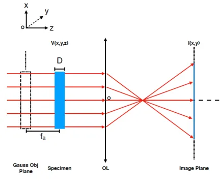
As shown in Figure 3, suppose the thickness of the specimen is , the underfocus of the 19
proximal side is , and that of the distal side is + , the averaged underfocus of the specimen 20
( , ) = ( , )⨂ ( , , ) (4) 1
where, ( , ) is the projection of the structural density ( , , ) of the specimen, 2
( , ) = ( , , ) (5) 3
and ( , , ) is the point spread function of the objective lens, and is the Fourier 4
transformation of contrast transfer function, 5
, , = ( , ) = ( − ) (6)
6
For simplicity, here we do not consider astigmatism and amplitude contrast and therefore =
7
+ .
8
However, when the thickness D is large enough, equation (4) has to be corrected by dividing 9
the specimen into a series of thin specimen (n=0, 1, 2, …, N-1), thus the final image of a thick 10
specimen can be formulated as, 11
( , ) = ∑ ∆ ∗ ( , , + ∆ ) ⨂ ( + ∆ , , ) (7)
12
When → +∞, we have, 13
( , ) = ( , , + )⨂ ( + , , )
14
= ( , , + )⨂ ( + , , ) (8) 15
Considering (~ 100 ) ≪ (1000 ~ 2500 ), the point spread function can be expanded 16
( + , , ) = ( , , ) + ∗ | (9) 1
Combining (8) and (9), we have, 2
( , ) = ( , ) + ( , ) (10) 3
( , ) = ( , , + ) ⨂ ( , , ) (11)
4
( , ) = ( , , + ) ⨂ | (12)
5
Next, we consider Fourier transformation of the structural density ( , , ) of the specimen, 6
, , = ∬ ( , , + ) ∗ (13)
7
Thus, we have the projection theorem, 8
, , 0 = ∬ ( , , + ) ∗
9
=∬ ( , ) ∗ (14) 10
and the following relationship, 11
| = ( , , + ) ∗ ∗ (− ) |
12
= ∬ ( , , + ) ∗ (15)
13
As a result, combining (14) and (15) and utilizing the convolution theorem, the Fourier 14
, = , , 0 ∗ ( , ) + | ∗ ( , )| (16) 1
Combining (6) and (16), we have, 2
, = , , 0 ∗ ( , ) − ∗ ( , ) ∗ (17)
3
From (17), it is clear to see, for the thick specimen, the Fourier transformation of cryo-EM image 4
contains an additional term ∗ ( , ) ∗ . This term has a minor contribution at 5
the low resolution but will interfere significantly with the first term and induce Thon ring fading out 6
at the high resolution. 7
Equation (17) provides at least two ways to solve and correct the focus gradient effect. For the 8
first way, we can take two cryo-EM images of the same specimen with different underfocus, yielding 9
two equations. The underfocus parameters can be accurately estimated by fitting Thon ring and 10
using the low resolution data. Then the structural factor , , 0 can be solved directly. The 11
concern of reduced SNR from additional radiation damage of the second exposure has been 12
discussed carefully and can be eliminated [65]. 13
The second way does not need two experimental images but apply an iterative algorithm to solve 14
the structural factor. Initially, the second term of (17) is neglected and normal cryo-EM SPA 15
procedure is performed to get the first round of structure. Then can be computed and will be 16
used to update the structural factor , , 0 according to (17). Therefore, the structure of cryo-17
EM map can be reconstructed again with an improved resolution. This procedure can be iterated 18
2.4 Beam induced motion and radiation damage
1
Cryo-EM of bio-macromolecules embedded in vitreous ice has suffered from beam induced 2
motion (BIM) for many years. When accelerated high-energy electrons interact with the specimen, 3
the electrons from the specimen will be scattered and become secondary electrons coming out of 4
the specimen, leaving positively charged annulus at the illumination area [73]. This is called 5
charging effect (‘Berriman effect’) from electron beam illumination. Since the thin layer of vitreous 6
ice is an insulator, the positive charges can not be quickly compensated from the environment and 7
thus induce the subsequent physical effects. First, the irregular and metastable structure of the 8
vitrified ice can easily respond the internal electrostatic repulsion stress from the positive charges 9
and thus result a global mechanical deformation. Such global mechanical deformation is much 10
significant at the beginning of electron illumination [16] and was observed to have a dome-like 11
shape [74]. The mechanical deformation of the ice layer during electron illumination will result a 12
blurred cryo-EM image and weaken the high resolution information significantly. Second, the 13
positive charged annulus will induce additional phase shift of electron beam just like a microscopic 14
electrostatic lens, which will induce an additional contrast loss and blurring of the final image [73], 15
which, however and fortunately, has the minimal effect on the high resolution cryo-EM SPA 16
technique according to the recent study [75]. 17
Besides charging effect that causes BIM, electron beam illumination will induce another more 18
severe effect, which is called radiation damage (or radiolysis). When the secondary electron is 19
kicked out, the chemical covalent bond of molecule will be broken, generating many free-radicals. 20
of bio-macromolecule can be damaged effectively from the electron beam illumination and the high 1
resolution structural information will be damped significantly when the illumination dose increased 2
[2, 76]. Thus, electron radiation damage must be carefully considered and the electron dose should 3
be carefully controlled for high resolution cryo-EM SPA work. 4
The electron radiation damage of vitreous ice embedded bio-macromolecules will further cause 5
the ‘bubbling’ effect that is routinely observed in cryo-EM experiments. Since both water molecules 6
and bio-macromolecules contain abundant hydrogen atoms, electron radiolysis will generate large 7
amount of hydrogen free-radicals and these hydrogen free-radicals will react subsequently to form 8
hydrogen molecule [77]. At the interfaces between bio-macromolecules and ice or the support 9
carbon film and ice, hydrogen molecules are frequently accumulated into a high concentration and 10
form the hydrogen gas pocket, which was observed as the ‘bubbling’ effect [78]. The generation of 11
hydrogen gas pocket will produce additional mechanical stress within the cryo-vitrified specimen 12
and thus become another factor of BIM. By using a very low electron radiation dose-rate, the 13
accumulation of hydrogen gas can be effectively decreased and thus the ‘bubbling’ effect can be 14
alleviated [78]. To be noted, the ‘bubbling’ effect used to be developed as a kind of technique to 15
study the internal nucleic structure of virus [79]. 16
Recently, another kind of BIM effect, called beam-induced Brownian motion, was proposed 17
and studied [80]. This effect describes a pseudo-Brownian motion of vitreous ice embedded bio-18
macromolecules, which is generated from the beam-induced movement of water molecules. 19
Fortunately, the experimental data and simulation study by Henderson and coworkers suggested that 20
the size of bio-macromolecule is small and the target resolution goes beyond 2 angstrom [80]. 1
The existence of BIM and electron radiation damage has been aware of the key bottleneck of 2
high resolution cryo-EM SPA for many years until the emerging of the direct electron detector (DED) 3
[81]. The high detective quantum efficiency (DQE) of the DED camera [82] allows to retain the 4
high resolution weak signal under low dose electron radiation that is important to reduce radiation 5
damage of bio-macromolecules. Equally importantly, the CMOS architecture of DEM camera 6
enables a high frame rate to record a single exposure into a movie, which can be utilized to correct 7
BIM efficiently by applying appropriate image processing algorithms [16, 74, 83]. In addition, by 8
using dose fractionation and damage compensation algorithms, the movie mode of DED camera can 9
further allow to use a high illumination dose to take cryo-EM images for a better contrast [76]. 10
Besides the direct electron detector that can correct BIM during image processing procedure, 11
additional efforts have been also performed to alleviate BIM effect and these include spot scan 12
imaging [84, 85], paraxial charge compensator [86], and development of various supporting films 13
such Cryo-Mesh grid, graphene film and pure gold grid [87-89]. The pure gold grid was proved to 14
have sufficient mechanical stiffness and good conductivity, which can therefore reduce BIM [88] 15
and has been successfully applied in many high resolution cryo-EM SPA applications [90]. 16
Overall, the efforts of developing direct electron detector, motion correction algorithms and 17
new types of supporting films in recent years have significantly reduce the effects from BIM and 18
electron radiation damage. More and more bio-macromolecular structures are solved to near atomic 19
resolution (3 ~ 4 angstrom) by cryo-EM SPA approach and there were a few cases reaching sub-2 20
be the most important bottleneck of cryo-EM SPA in the future to achieve atomic resolution. 1
Previous studies have showed that the high resolution (~ 3 angstrom) information of vitreous 2
embedded biological specimen starts falling off after a low dose (3 /Å ) of electron radiation [2]. 3
The severe mechanical deformation of ice layer at the first dose fractionated frames could not be 4
corrected by image processing algorithms [16]. As a result, while the first couple of frames with less 5
radiation damage contains atomic resolution information, this information can not be restored due 6
to a large BIM and thus these frames have to be discarded in the subsequent image processing. 7
In the future, there will be two potential ways to further alleviate the electron radiation damage 8
effect. The first possible way is to utilize quantum entanglement effect of electrons to reduce the 9
shot noise of electron beam from the normal scale ~1/ / to the Heisenberg limit ~1/ [32,
10
91]. As a result, we could utilize an even low electron dose (1 /Å ) to capture a good image with 11
enough SNR and less radiation damage [91]. The other possible way is to consider the time scale of 12
electron radiation damage. If we could take cryo-EM image before the specimen damage occurs, 13
we thus could have an opportunity of obtaining the damage-free and high resolution structure of 14
bio-macromolecule. This idea has been proved in the field of serial femtosecond X-ray 15
crystallography with the term of ‘diffraction before damage’ [92]. In cryo-EM of bio-16
macromolecules, it is important to estimate the time scale of specimen damage from electron 17
radiation and then verify the possibility of the term of ‘imaging before damage’. 18
For 300kV transmission electron microscope, the accelerated electron gains a high speed v =
19
c 1 − = 0.78 = 2.3 × 10 ⁄ , where the relativistic effect has to be considered, the
static energy of electron is = = 511 , the kinetic energy is E = 300keV and the light 1
speed in vacuum is = 3 × 10 ⁄ . Then, the time for an electron traveling across a specimen 2
with the thickness of = 100 is ∆ = = 0.33 . Thus, we could estimate the time scale of 3
the interaction between the specimen and the high energy electron is ~1 . Then there will be 4
many damage events occurred in the biological specimen, which can be divided into two processes, 5
the primary damage process and the secondary damage process [93, 94]. The primary damage 6
process includes chemical bond breaking, ionization, and production of secondary electrons and free 7
radicals. Previous studies suggested that the time scale of the primary damage process is 1~10
8
and such damage does not influence the electron microscopic image appreciably [95], because the 9
positions of atoms do not change noticeably at this time scale. The only detectable damage in the 10
electron microscopic image occurs in the secondary process, which initiates from the transition of 11
free radicals and includes subsequent cascade reactions induced by free radicals and productions of 12
new chemical bonds. During the second process, the positions of atoms in the specimen have 13
changed significantly, resulting appreciable damage effect in the final electron microscopic image. 14
The time scale of the second process depends on the rate of free radical transition, which can be 15
estimated as below. 16
As discussed above, the abundant free radicals generated from vitreous ice embedded bio-17
macromolecules are hydrogen free radicals ∗. The transition of ∗ follows the Fick’s laws of
18
diffusion, 19
= = − ∙ (18) 20
can be calculated according to Stokes-Einstein relationship, 1
= (19) 2
where, is the Boltzmann constant (1.38E-23 J/K), is the temperature of vitrified specimen, 3
is the viscosity of the vitreous ice, and (~10 ) is the radius of ∗. Combining (18) and 4
(19), we can calculate the transition rate of ∗ as,
5
= ∙ ∙ (20) 6
Suppose, initially, the free radicals ∗ are concentrated in a small cubic region with the size of 1 7
, thus we could have the following estimation, 8
∙ = ∙∆∆ ~∆ ~10 (21) 9
Thus, at the temperature ( = 90 ) of cryo-EM experiments, the transition rate of ∗ can be
10
estimated as, 11
~ × . ×. × ×× × 10 = 0.7 ⁄ (22) 12
Then the time for ∗ traveling 0.3 , the averaged distance to reach adjacent groups and then 13
perform radical reaction, can be estimated as, 14
∆t~ . /. = 0.4 (23) 15
To be noted that, the estimation in (22) utilizes the water viscosity at room temperature, =
16
than ten times) than the water viscosity at room temperature. Therefore, the time scale for the second 1
damage process is in the nanoseconds ~10 . 2
The above estimation suggests that if we could take a cryo-EM exposure within 10 , the 3
appreciable electron radiation damage during the second process can be almost avoided in the final 4
recorded micrograph. The recent developed ultrafast transmission electron microscopy (UEM) [96-5
99] has actually provided an opportunity to test this kind of idea. There are two operation modes of 6
UEM, the stroboscopic mode with picosecond temporal resolution and the single-pulse mode with 7
nanosecond temporal resolution [97]. The stroboscopic mode is useful for ultrafast electron 8
diffraction experiments and suitable to study the reversible process of the material. However, the 9
electron radiation damage of bio-macromolecules is irreversible. Thus, to achieve the concept of 10
‘imaging before damage’, it is necessary to develop the cryo-ultrafast transmission electron 11
microscopy (cryo-UEM) that is operated in the single-pulse mode. Although there have been some 12
reports of using UEM to observe the biological specimens [100-102], all these studies were 13
performed in the stroboscopic mode and utilized the dehydrated specimen, which should not be 14
relevant to biological functions. There is still a big space to develop and improve the single-pulse 15
UEM technology. We are looking forward to the future maturation of cryo-UEM that will bring the 16
bio-macromolecular electron microscopy into a new era. 17
3. Conclusions
18
Cryo-EM SPA has become the most important technique of bio-macromolecular electron 19
microscopy. The era of studying the structures of bio-macromolecules by using Cryo-EM SPA is 20
complexes whose structures are solved into near atomic resolution, making significant implications 1
to their biological functions. However, just as Henderson [103] and Glaeser [32] pointed, cryo-2
electron microscopy has not yet realized its full potential. In the future, with a better cryo-3
vitrification technique to avoid air-water interface problem, with a better camera and new type of 4
microscope to further alleviate electron radiation damage effect and with some novel image 5
processing algorithms and experimental techniques to solve the focus gradient problem as well as 6
the conformational heterogeneity issue, Cryo-EM SPA will expand its full ability to solve the atomic 7
resolution of bio-macromolecules. 8
ACKNOWLEDGEMENTS
9
I would like to apologize that there are also many other pioneer works of developing bio-10
macromolecular electron microscopy, which are not mentioned in this review due to limited space. 11
I would like to thank Dr. Xiaojun Huang for her critical comments of the manuscript, Shuangbo 12
Zhang for his assistance of literatures searching, and Ping Shan and Ruigang Su for their assistances 13
in the lab management. This work is supported by grants from Chinese Academy of Sciences 14
(ZDKYYQ20170002 and XDB08030202) and Ministry of Science and Technology of China 15
(
2017YFA0504700
and 2014CB910700).16
References
1
[1] Downing K H 1988 Observations of restricted beam-induced specimen motion with 2
small-spot illumination
Ultramicroscopy
24 387-97 3[2] Hayward S B and Glaeser R M 1979 Radiation damage of purple membrane at low 4
temperature
Ultramicroscopy
04 201-10 5[3] Adrian M, Dubochet J, Lepault J and McDowall A W 1984 Cryo-electron microscopy 6
of viruses
Nature
308 32-6 7[4] Taylor K A and Glaeser R M 1974 Electron diffraction of frozen, hydrated protein 8
crystals
Science (New York, N.Y
186 1036-7 9[5] Frank J 1990 Classification of macromolecular assemblies studied as 'single particles' 10
Quarterly reviews of biophysics
23 281-32911
[6] Henderson R and Unwin P N 1975 Three-dimensional model of purple membrane 12
obtained by electron microscopy
Nature
257 28-32 13[7] Henderson R 1995 The potential and limitations of neutrons, electrons and X-rays for 14
atomic resolution microscopy of unstained biological molecules
Quarterly reviews of
15biophysics
28 171-9316
[8] Scheres S H 2012 RELION: implementation of a Bayesian approach to cryo-EM 17
structure determination
Journal of structural biology
180 519-30 18[9] Grigorieff N 2016 Frealign: An Exploratory Tool for Single-Particle Cryo-EM
Methods
19Enzymol
579 191-22620
[10] Punjani A, Rubinstein J L, Fleet D J and Brubaker M A 2017 cryoSPARC: algorithms for 21
rapid unsupervised cryo-EM structure determination
Nature methods
22[11] Suloway C, Pulokas J, Fellmann D, Cheng A, Guerra F, Quispe J, Stagg S, Potter C S and 23
Carragher B 2005 Automated molecular microscopy: the new Leginon system
Journal
24of structural biology
151 41-60 25[12] Mastronarde D 2003 SerialEM A Program for Automated Tilt Series Acquisition on 26
Tecnai Microcopes Using Prediction of Specimen Position
Microscopy and
27Microanalysis
9 1182-3 28[13] Biyani N, Righetto R D, McLeod R, Caujolle-Bert D, Castano-Diez D, Goldie K N and 29
Stahlberg H 2017 Focus: The interface between data collection and data processing in 30
analysis using the Volta phase plate
Journal of structural biology
1[15] Khoshouei M, Radjainia M, Phillips A J, Gerrard J A, Mitra A K, Plitzko J M, Baumeister 2
W and Danev R 2016 Volta phase plate cryo-EM of the small protein complex Prx3 3
Nat Commun
7 105344
[16] Li X, Mooney P, Zheng S, Booth C R, Braunfeld M B, Gubbens S, Agard D A and Cheng 5
Y 2013 Electron counting and beam-induced motion correction enable near-atomic-6
resolution single-particle cryo-EM
Nature methods
7[17] Liao M, Cao E, Julius D and Cheng Y 2013 Structure of the TRPV1 ion channel 8
determined by electron cryo-microscopy
Nature
504 107-12 9[18] Bai X C, Fernandez I S, McMullan G and Scheres S H 2013 Ribosome structures to near-10
atomic resolution from thirty thousand cryo-EM particles
eLife
2 e00461 11[19] Kuhlbrandt W 2014 Biochemistry. The resolution revolution
Science (New York, N.Y
12343 1443-4 13
[20] Merk A, Bartesaghi A, Banerjee S, Falconieri V, Rao P, Davis M I, Pragani R, Boxer M B, 14
Earl L A, Milne J L and Subramaniam S 2016 Breaking Cryo-EM Resolution Barriers to 15
Facilitate Drug Discovery
Cell
165 1698-707 16[21] Yan C, Hang J, Wan R, Huang M, Wong C C and Shi Y 2015 Structure of a yeast 17
spliceosome at 3.6-angstrom resolution
Science (New York, N.Y
349 1182-91 18[22] Wei X, Su X, Cao P, Liu X, Chang W, Li M, Zhang X and Liu Z 2016 Structure of spinach 19
photosystem II-LHCII supercomplex at 3.2 A resolution
Nature
534 69-74 20[23] Vinothkumar K R, Zhu J and Hirst J 2014 Architecture of mammalian respiratory 21
complex I
Nature
advance online publication 22[24] Rosenthal P B and Henderson R 2003 Optimal determination of particle orientation, 23
absolute hand, and contrast loss in single-particle electron cryomicroscopy
Journal of
24molecular biology
333 721-4525
[25] Briggs J A 2013 Structural biology in situ--the potential of subtomogram averaging 26
Curr Opin Struct Biol
23 261-7 27[26] Gonen T, Cheng Y, Sliz P, Hiroaki Y, Fujiyoshi Y, Harrison S C and Walz T 2005 Lipid-28
protein interactions in double-layered two-dimensional AQP0 crystals
Nature
438 29633-8 30
[27] Shi D, Nannenga B L, Iadanza M G and Gonen T 2013 Three-dimensional electron 31
electron microscopy
Chem Rev
111 7710-48 1[29] Cheng Y 2015 Single-Particle Cryo-EM at Crystallographic Resolution
Cell
161 450-7 2[30] Thompson R F, Walker M, Siebert C A, Muench S P and Ranson N A 2016 An 3
introduction to sample preparation and imaging by cryo-electron microscopy for 4
structural biology
Methods
100 3-15 5[31] Patwardhan A 2017 Trends in the Electron Microscopy Data Bank (EMDB)
Acta
6Crystallogr D Struct Biol
73 503-8 7[32] Glaeser R M 2016 How good can cryo-EM become?
Nature methods
13 28-32 8[33] Glaeser R M, Han B G, Csencsits R, Killilea A, Pulk A and Cate J H 2016 Factors that 9
Influence the Formation and Stability of Thin, Cryo-EM Specimens
Biophys J
110 749-1055 11
[34] Glaeser R M and Han B G 2017 Opinion: hazards faced by macromolecules when 12
confined to thin aqueous films
Biophys Rep
3 1-7 13[35] Noble A J, Dandey V P, Wei H, Brasch J, Chase J, Acharya P, Tan Y Z, Zhang Z, Kim L Y, 14
Scapin G, Rapp M, Eng E T, Rice W J, Cheng A, Negro C J, Shapiro L, Kwong P D, 15
Jeruzalmi D, des Georges A, Potter C S and Carragher B 2017 Routine Single Particle 16
CryoEM Sample and Grid Characterization by Tomography
bioRxiv
17[36] Raffaini G and Ganazzoli F 2010 Protein adsorption on a hydrophobic surface: a 18
molecular dynamics study of lysozyme on graphite
Langmuir
26 5679-89 19[37] Yu G, Li K and Jiang W 2016 Antibody-based affinity cryo-EM grid
Methods
20[38] Kelly D F, Dukovski D and Walz T 2010 Strategy for the use of affinity grids to prepare 21
non-His-tagged macromolecular complexes for single-particle electron microscopy 22
Journal of molecular biology
400 675-8123
[39] Quinn P J and Dawson R M 1970 An analysis of the interaction of protein with lipid 24
monolayers at the air-water interface
Biochem J
116 671-80 25[40] Razinkov I, Dandey V, Wei H, Zhang Z, Melnekoff D, Rice W J, Wigge C, Potter C S and 26
Carragher B 2016 A new method for vitrifying samples for cryoEM
Journal of structural
27biology
195 190-828
[41] Arnold S A, Albiez S, Bieri A, Syntychaki A, Adaixo R, McLeod R A, Goldie K N, Stahlberg 29
H and Braun T 2017 Blotting-free and lossless cryo-electron microscopy grid 30
preparation from nanoliter-sized protein samples and single-cell extracts
Journal of
31effects of particle adsorption to the air-water interface in cryoEM
bioRxiv
1[43] Scheres S H, Gao H, Valle M, Herman G T, Eggermont P P, Frank J and Carazo J M 2007 2
Disentangling conformational states of macromolecules in 3D-EM through likelihood 3
optimization
Nature methods
4 27-9 4[44] Zhang K, Foster H E, Rondelet A, Lacey S E, Bahi-Buisson N, Bird A W and Carter A P 5
2017 Cryo-EM Reveals How Human Cytoplasmic Dynein Is Auto-inhibited and 6
Activated
Cell
169 1303-14 e18 7[45] Fischer N, Konevega A L, Wintermeyer W, Rodnina M V and Stark H 2010 Ribosome 8
dynamics and tRNA movement by time-resolved electron cryomicroscopy
Nature
466 9329-33 10
[46] Van Heel M and Frank J 1981 Use of multivariate statistics in analysing the images of 11
biological macromolecules
Ultramicroscopy
6 187-94 12[47] van Heel M 1984 Multivariate statistical classification of noisy images (randomly 13
oriented biological macromolecules)
Ultramicroscopy
13 165-83 14[48] Sigworth F J, Doerschuk P C, Carazo J M and Scheres S H 2010 An introduction to 15
maximum-likelihood methods in cryo-EM
Methods Enzymol
482 263-94 16[49] Scheres S H 2012 A Bayesian view on cryo-EM structure determination
Journal of
17molecular biology
415 406-1818
[50] Voorhees R M, Fernandez I S, Scheres S H and Hegde R S 2014 Structure of the 19
mammalian ribosome-Sec61 complex to 3.4 A resolution
Cell
157 1632-43 20[51] Shan H, Wang Z, Zhang F, Xiong Y, Yin C C and Sun F 2016 A local-optimization 21
refinement algorithm in single particle analysis for macromolecular complex with 22
multiple rigid modules
Protein & cell
7 46-62 23[52] Bai X C, Rajendra E, Yang G, Shi Y and Scheres S H 2015 Sampling the conformational 24
space of the catalytic subunit of human gamma-secretase
eLife
4 25[53] Nakane T, Kimanius D, Lindahl E and Scheres S H W 2018 Characterisation of molecular 26
motions in cryo-EM single-particle data by multi-body refinement in RELION
bioRxiv
27[54] Zhou Q, Zhou N and Wang H W 2017 Particle segmentation algorithm for flexible 28
single particle reconstruction
Biophys Rep
3 43-55 29[55] Jin Q, Sorzano C O, de la Rosa-Trevin J M, Bilbao-Castro J R, Nunez-Ramirez R, Llorca 30
O, Tama F and Jonic S 2014 Iterative elastic 3D-to-2D alignment method using normal 31
[56] Frank J and Ourmazd A 2016 Continuous changes in structure mapped by manifold 1
embedding of single-particle data in cryo-EM
Methods
2[57] Sorzano C O, de la Rosa-Trevin J M, Tama F and Jonic S 2014 Hybrid Electron 3
Microscopy Normal Mode Analysis graphical interface and protocol
Journal of
4structural biology
188 134-41 5[58] Sanchez Sorzano C O, Alvarez-Cabrera A L, Kazemi M, Carazo J M and Jonic S 2016 6
StructMap: Elastic Distance Analysis of Electron Microscopy Maps for Studying 7
Conformational Changes
Biophys J
110 1753-65 8[59] Schilbach S, Hantsche M, Tegunov D, Dienemann C, Wigge C, Urlaub H and Cramer P 9
2017 Structures of transcription pre-initiation complex with TFIIH and Mediator
Nature
10551 204-9 11
[60] Schwander P, Fung R and Ourmazd A 2014 Conformations of macromolecules and 12
their complexes from heterogeneous datasets
Philos Trans R Soc Lond B Biol Sci
369 1320130567 14
[61] Schwander P, Fung R, G. N. Phillips J and Ourmazd A 2010 Mapping the conformations 15
of biological assemblies
New Journal of Physics
12 035007 16[62] Dashti A, Schwander P, Langlois R, Fung R, Li W, Hosseinizadeh A, Liao H Y, Pallesen J, 17
Sharma G, Stupina V A, Simon A E, Dinman J D, Frank J and Ourmazd A 2014 18
Trajectories of the ribosome as a Brownian nanomachine
Proc Natl Acad Sci U S A
111 1917492-7 20
[63] Jonic S 2017 Computational methods for analyzing conformational variability of 21
macromolecular complexes from cryo-electron microscopy images
Curr Opin Struct
22Biol
43 114-21 23[64] Yan R, Edwards T J, Pankratz L M, Kuhn R J, Lanman J K, Liu J and Jiang W 2015 24
Simultaneous determination of sample thickness, tilt, and electron mean free path 25
using tomographic tilt images based on Beer-Lambert law
Journal of structural biology
26192 287-96 27
[65] DeRosier D J 2000 Correction of high-resolution data for curvature of the Ewald sphere 28
Ultramicroscopy
81 83-9829
[66] Zhang K 2016 Gctf: Real-time CTF determination and correction
Journal of structural
30biology
193 1-1231
[67] Wolf M, DeRosier D J and Grigorieff N 2006 Ewald sphere correction for single-particle 32
[68] Leong P A, Yu X, Zhou Z H and Jensen G J 2010
Methods in Enzymology,
ed J J Grant: 1Academic Press) pp 369-80 2
[69] Tan Y Z, Aiyer S, Mietzsch M, Hull J A, McKenna R, Grieger J, Samulski R J, Baker T S, 3
Agbandje-McKenna M and Lyumkis D 2018 Sub-2 Å Ewald Curvature Corrected 4
Single-Particle Cryo-EM
bioRxiv
5[70] Zhu D, Wang X, Fang Q, Van Etten J L, Rossmann M G, Rao Z and Zhang X 2018 6
Pushing the resolution limit by correcting the Ewald sphere effect in single-particle 7
Cryo-EM reconstructions
Nat Commun
9 1552 8[71] Yuan S, Wang J, Zhu D, Wang N, Gao Q, Chen W, Tang H, Wang J, Zhang X, Liu H, Rao 9
Z and Wang X 2018 Cryo-EM structure of a herpesvirus capsid at 3.1 A
Science (New
10York, N.Y
360 11[72] Downing K H and Glaeser R M 2017 Estimating the effect of finite depth of field in 12
single-particle cryo-EM
Ultramicroscopy
184 94-9 13[73] Brink J, Sherman M B, Berriman J and Chiu W 1998 Evaluation of charging on 14
macromolecules in electron cryomicroscopy
Ultramicroscopy
72 41-52 15[74] Brilot A F, Chen J Z, Cheng A, Pan J, Harrison S C, Potter C S, Carragher B, Henderson 16
R and Grigorieff N 2012 Beam-induced motion of vitrified specimen on holey carbon 17
film
Journal of structural biology
177 630-7 18[75] Russo C J and Henderson R 2018 Microscopic charge fluctuations cause minimal 19
contrast loss in cryoEM
Ultramicroscopy
187 56-63 20[76] Grant T and Grigorieff N 2015 Measuring the optimal exposure for single particle cryo-21
EM using a 2.6 A reconstruction of rotavirus VP6
eLife
4 e06980 22[77] Leapman R D and Sun S 1995 Cryo-electron energy loss spectroscopy: observations 23
on vitrified hydrated specimens and radiation damage
Ultramicroscopy
59 71-9 24[78] Chen J Z, Sachse C, Xu C, Mielke T, Spahn C M and Grigorieff N 2008 A dose-rate 25
effect in single-particle electron microscopy
Journal of structural biology
161 92-100 26[79] Cheng N, Wu W, Watts N R and Steven A C 2014 Exploiting radiation damage to map 27
proteins in nucleoprotein complexes: the internal structure of bacteriophage T7 28
Journal of structural biology
185 250-6 29[80] McMullan G, Vinothkumar K R and Henderson R 2015 Thon rings from amorphous ice 30
and implications of beam-induced Brownian motion in single particle electron cryo-31
Ellisman M H and Xuong N H 2008 Applications of direct detection device in 1
transmission electron microscopy
Journal of structural biology
161 352-8 2[82] McMullan G, Faruqi A R, Clare D and Henderson R 2014 Comparison of optimal 3
performance at 300keV of three direct electron detectors for use in low dose electron 4
microscopy
Ultramicroscopy
147 156-63 5[83] Zheng S Q, Palovcak E, Armache J P, Verba K A, Cheng Y and Agard D A 2017 6
MotionCor2: anisotropic correction of beam-induced motion for improved cryo-7
electron microscopy
Nature methods
14 331-2 8[84] Bullough P and Henderson R 1987 Use of spot-scan procedure for recording low-dose 9
micrographs of beam-sensitive specimens
Ultramicroscopy
21 223-30 10[85] Downing K H and Glaeser R M 1986 Improvement in high resolution image quality of 11
radiation-sensitive specimens achieved with reduced spot size of the electron beam 12
Ultramicroscopy
20 269-7813
[86] Berriman J A and Rosenthal P B 2012 Paraxial charge compensator for electron 14
cryomicroscopy
Ultramicroscopy
116 106-14 15[87] Russo C J and Passmore L A 2014 Controlling protein adsorption on graphene for 16
cryo-EM using low-energy hydrogen plasmas
Nature methods
17[88] Russo C J and Passmore L A 2016 Ultrastable gold substrates: Properties of a support 18
for high-resolution electron cryomicroscopy of biological specimens
Journal of
19structural biology
193 33-44 20[89] Yoshioka C, Carragher B and Potter C S 2010 Cryomesh: a new substrate for cryo-21
electron microscopy
Microsc Microanal
16 43-53 22[90] des Georges A, Clarke O B, Zalk R, Yuan Q, Condon K J, Grassucci R A, Hendrickson W 23
A, Marks A R and Frank J 2016 Structural Basis for Gating and Activation of RyR1
Cell
24167 145-57 e17 25
[91] Okamoto H 2012 Possible use of a Cooper-pair box for low-dose electron microscopy 26
Physical Review A
85 04381027
[92] Martin-Garcia J M, Conrad C E, Coe J, Roy-Chowdhury S and Fromme P 2016 Serial 28
femtosecond crystallography: A revolution in structural biology
Arch Biochem Biophys
29602 32-47 30
[93] Glaeser R M and Taylor K A 1978 Radiation damage relative to transmission electron 31
microscopy of biological specimens at low temperature: a review
Journal of
32[94] Hendrickson W A 1976 Radiation damage in protein crystallography
Journal of
1molecular biology
106 889-932
[95] Schnabl H 1980 Does removal of hydrogen change the electron energy-loss spectra 3
of DNA bases?
Ultramicroscopy
5 147-51 4[96] Zewail A H 2010 Four-dimensional electron microscopy
Science (New York, N.Y
328 5187-93 6
[97] Shorokhov D and Zewail A H 2016 Perspective: 4D ultrafast electron microscopy-7
Evolutions and revolutions
J Chem Phys
144 080901 8[98] Fu X, Chen B, Tang J, Hassan M T and Zewail A H 2017 Imaging rotational dynamics of 9
nanoparticles in liquid by 4D electron microscopy
Science (New York, N.Y
355 494-8 10[99] Cao G, Sun S, Li Z, Tian H, Yang H and Li J 2015 Clocking the anisotropic lattice 11
dynamics of multi-walled carbon nanotubes by four-dimensional ultrafast 12
transmission electron microscopy
Scientific reports
5 8404 13[100] Fitzpatrick A W, Lorenz U J, Vanacore G M and Zewail A H 2013 4D cryo-electron 14
microscopy of proteins
Journal of the American Chemical Society
135 19123-6 15[101] Fitzpatrick A W, Park S T and Zewail A H 2013 Exceptional rigidity and biomechanics 16
of amyloid revealed by 4D electron microscopy
Proc Natl Acad Sci U S A
110 10976-1781 18
[102] Lorenz U J and Zewail A H 2013 Biomechanics of DNA structures visualized by 4D 19
electron microscopy
Proc Natl Acad Sci U S A
110 2822-7 20[103] Henderson R 2015 Overview and future of single particle electron cryomicroscopy
Arch
21Biochem Biophys
2223
Figures
1 2
3
Figure 1. Statistics of the electron density maps deposited in EMDB (Electron Microscopy
4
Data Bank). The annual numbers of released maps with different reported resolutions are plotted 5
from 2002 to 2017 (left). And the distribution of all the released maps till 2017 is statistically plotted 6
vs different resolutions (right). Both panels were generated using the tool of EMDB 7
(http://www.ebi.ac.uk/pdbe/emdb). 8
1
Figure 2. Air-water interface effects during specimen cryo-vitrification. A. The bio-2
macromolecule specimen exhibits homogenous distribution and good shape in negative electron 3
microscopy (left), but is prone to degrade and hard to observe in cryo-electron microscopy (right). 4
Scale bar, 50 nm. B. A diagram showing the physical process during specimen cryo-vitrification. 5
Bio-macromolecules in native state (AV) are colored in pink, those (AS) absorbed to air-water
6
interface are colored in orange, and that (AD) denatured in yellow. The thickness (t) of the solution
7
1
Figure 3. A diagram showing the image formation of a think specimen with the averaged
2
underfocus fa. Gauss Obj Plane, the plane where the idea objective locates according to Gauss 3
image formation formula. D, the thickness of the specimen. OL, objective lens. V(x,y,z), the density 4