Miniaturized Microstrip Lowpass Filter with Compact Size
for Harmonic Suppression
Guan-Nan Chen1 and Jing-Bo Hu2, *
Abstract—A new miniaturized microstrip lowpass filter with compact size and a wide spurious-free stopband is investigated. To achieve compact design and ultra-wide band rejection, both triangular patch resonators and trapezoid patch resonators are introduced in the filter. To further reduce the circuit size of the filter, the meander transmission line is also adopted in the design. A demonstration filter with 3 dB cutoff frequency at 0.76 GHz has been designed, fabricated and measured. Results indicate that the proposed filter is able to suppress the 16th harmonic response referred to a suppression degree of 15 dB. Furthermore, the proposed filter exhibits a small size of 0.080λg×0.072λg, whereλg is the guided wavelength at 0.76 GHz.
1. INTRODUCTION
Planar lowpass filters with compact size and high performance are in great demand for wireless communication systems to suppress harmonics and spurious signals because of their easy fabrication, low cost and easy integration with other microwave circuits. Conventional lowpass filters using shunt stubs or high-low impedance transmission lines have been widely used in microwave systems for their remarkable characteristics [1]. However, it is hard to achieve compact size and high performance simultaneously. Thus, techniques to achieve both size reduction and performance enhancement have been studied in recent years [2–8].
The usual approach to design a compact lowpass filter with high performance and compact size is to form a lowpass filter by cascading multiple resonators [2–5]. A lowpass filter was designed by cascading multi-radial patch resonators in [2], but the size of the filter was relatively large. A lowpass filter featured harmonic response was achieved based on cascading tapered resonant cells in [3], but it is hard to achieve a compact size and stopband performance. Therefore, to further improve the stopband performance, a lowpass filter was proposed by cascading LC resonant structures and transformed radial stubs. Although better than 13th harmonic suppression had been realized, this method also increased design complexity and circuit area in [4]. A lowpass filter with low insertion loss and sharp roll-off was proposed by cascading modified microstrip patch resonators consisting of semi-circles and semi-ellipses in [5]. However, the compact size and stopband bandwidth still need to be improved. A lowpass filter with 7th harmonic suppression performance was reported using stepped impedance hairpin resonator in [6]. Although compact design had been realized with this method, further improvement should be carried out in stopband bandwidth. On the other hand, filter design is not restricted in the 2-D level. Using defected ground structure is also a popular and useful way, which though increases the circuit complexity in [7].
Based on the previous works [8], a new miniaturized microstrip lowpass filter with compact size and a wide spurious-free stopband is proposed and implemented in this Letter. Both triangular patch
Received 5 July 2018, Accepted 16 August 2018, Scheduled 27 August 2018 * Corresponding author: Jing-Bo Hu (mwhujb@aliyun.com).
resonators and trapezoid patch resonators are used in the filter to achieve compact size and ultra-wide band rejection. To further reduce the circuit size, the meander transmission line is adopted in the filter design. Measured results indicate that the designed filter has a harmonic suppression rejection better than 15 dB from 1.52 to 12.84 GHz, together with less than 0.3 dB insertion loss in the passband. Furthermore, the size of the filter is only 16.8 mm×15.3 mm, which corresponds to a compact electrical size of 0.080λg×0.072λg, whereλg is the guided wavelength at 0.79 GHz.
2. FILTER DESIGN
Figure 1 shows the layout of the present lowpass filter, which is composed of a high-low impedance microstrip main transmission line and two types of resonators, i.e., resonator Ra and resonator Rb. Resonator Ra is a triangular patch. ResonatorRb is composed of a high impedance transmission line and a trapezoid patch, which are connected in series. To illustrate the design concept of the proposed filter, frequency response caused by the resonatorRa has been studied. As can be seen from Fig. 2(a), the proposed filter with only resonatorRa exhibits a wide stopband together with one transmission zero inside the stopband. Fig. 2(b) shows the resonant properties of The loaded resonator Rb coupled with adjacent triangular patches, i.e., resonatorRa, will not only enhance the shunt capacitance of the main transmission line but also provide extra finite transmission zeros inside the stopband. Therefore, the proposed lowpass filter has a low cutoff frequency and a harmonic suppression. Furthermore, to achieve miniaturized circuit design, one meander transmission line is also introduced to replace the internal high-impedance line of the filter. Thus, the size of the proposed lowpass filter can be further reduced.
l1
l2
l3
l4
w1
w2
w3
w4
m
n
g w5
Ra
Rb
θ
Figure 1. Layout of proposed lowpass filter.
Figure 3 shows the lumped-element equivalent circuit of the proposed lowpass filter. As shown in Fig. 3, Ca mainly represents the capacitance between the triangular patch and the ground plane. Cb mainly represents the capacitance between the trapezoid patch and the ground plane. And Cab
represents the coupled capacitance between the triangular patch and trapezoid patch. Clearly, the location of the 3 dB cutoff frequency and stopband performance is mainly controlled by the values ofL, Lb,LabandCb. On the other hand, the frequency locations of the transmission zeros inside the stopband can be controlled by the values ofCa andCab. Moreover, bothCab andL can increase capacitance and inductance of the circuit. As the above-mentioned properties are valuable for our design, a lowpass filter with enhanced stopband performance and compact size can be realized.
0 2 4 6 8 10 12 14 16 18 Frequency (GHz)
(a) (b)
0 2 4 6 8 10 12 14
Frequency (GHz) 0
-10
-20
-30
-40
-50
-60
S
-parameters (dB)
0
-10
-20
-30
-40
-50
-60
S
-parameters (dB)
-70 S
S11
21 S
S11
21
Figure 2. Simulated S-parameters of studied resonator. (a) Filter with only resonator Ra. (b) Filter with resonatorRa and resonator Rb.
Ca
Ca
Ca
Ca Cb
Cb Cab
Cab
Cab
Cab
Cb
Cb L
Lb
Lb Lb
Lb
Lab Lab
Figure 3. Lumped-element equivalent circuit of the proposed lowpass filter.
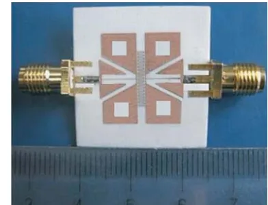
Figure 4. Photograph of the proposed lowpass filter.
θ= 63◦. The substrate used here has a relative dielectric constant of 3.45 and thickness of 0.508 mm. Fig. 4 is a photograph of the proposed lowpass filter.
3. EXPERIMENTAL RESULTS
0 2 4 6 8 10 12 14 Frequency (GHz)
-10
-20
-30
-40
-50
-60
S
-parameters (dB)
|S 11| Sim.
21
0
-70
-80
|S | Sim.
|S | Meas.
|S | Meas.
11 21
Figure 5. Simulated and measured performance of proposed filter.
Table 1. Performance comparisons among published filters and proposed one.
Ref. Harmonic suppression Maximum passband
insertion loss (dB) Circuit size
[2] 6th 0.5 0.351λg×0.106λg
[3] 11th 1.0 0.356λg×0.108λg
[4] 13th 1.5 0.310λg×0.240λg
[5] 6th 0.3 0.395λg×0.151λg
[6] 7th 0.5 0.104λg×0.104λg
[7] 6th 1.2 0.273λg×0.237λg
This work 16th 0.3 0.080λg×0.072λg
proposed filter has a property of 16th harmonic suppression. Furthermore, the size of the lowpass filter is only 16.8 mm×15.3 mm, which corresponds to an electrical size of 0.080λg×0.072λg, whereλg is the
waveguide length at 0.79 GHz. For comparison, Table 1 summarizes the performance of some published lowpass filters. As can be seen from the table, our proposed filter has the properties of miniaturized circuit size, low passband insertion loss, and good harmonic suppression among the quoted filters.
4. CONCLUSION
A new miniaturized microstrip lowpass filter with compact size and a wide spurious-free stopband is investigated in this letter. One prototype filter with 3 dB cutoff frequency at 0.79 GHz has been demonstrated. Results indicate that the proposed filter demonstrates many attractive features with compact circuit size, low passband insertion loss, and wide spurious-free stopband. With all these good features, the proposed filter is applicable to modern communication systems.
ACKNOWLEDGMENT
REFERENCES
1. Pozar, D. M., Microwave Engineering, 3rd Edition, 412–415, Wiley, New York, USA, 2005.
2. Li, J.-L., S.-W. Qu, and Q. Xue, “Compact microstrip lowpass filter with sharp roll-off and wide stop-band,”Electron. Lett., Vol. 45, No. 2, 110–111, 2009.
3. Li, L., Z.-F. Li, and Q.-F. Wei, “Compact and selective lowpass filter with very wide stopband using tapered compact microstrip resonant cells,” Electron. Lett., Vol. 45, No. 5, 267–268, 2009. 4. Ma, K. X. and K. S. Yeo, “New harmonic suppression low-pass filter using transformed radial
stubs,” IEEE Trans. Microw. Theory Tech., Vol. 59, No. 3, 604–611, 2011.
5. Hayati, M., A. Sheikhi, and A. Lotfi, “Compact lowpass filter with wide stopband using modified semi-elliptic and semi-circular microstrip patch resonator,” Electron. Lett., Vol. 46, No. 22, 1507– 1509, 2010.
6. Wei, X.-B., P. Wang, M.-Q. Liu, and Y. Shi, “Compact wide-stopband lowpass filter using stepped impedance hairpin resonator with radial stubs,”Electron. Lett., Vol. 47, No. 15, 862–863, 2011. 7. Wei, F., L. Chen, X.-W. Shi, Q.-L. Huang, and X.-H. Wang, “Compact lowpass filter with wide
stop-band using coupled-line hairpin unit,”Electron. Lett., Vol. 46, No. 1, 88–90, 2010.