The Effect of the Discharge Chamber Structure on the Performance
of a 5 cm-Diameter ECR Ion Thruster
Yujun Ke, Xinfeng Sun*, Yong Zhao, and Xuekang Chen
Abstract—Design and experimental optimization of a 5 cm-diameter electron cyclotron resonance (ECR) Ion Thruster was carried out. The experimental results with the shorten discharge chamber demonstrated that its maximum efficiency, specific impulse, and thrust were 38%, 4300 s, 2.3 mN with the power of 130 W, respectively. The beam current was increased with the increment of the propellant flow rate and screen grid voltage. In addition, the performance of the thruster was associated with the distance of the antenna and screen grid. However, the optimum distance depended on the input microwave power which was about 20 W.
1. INTRODUCTION
In recent years, the demand of small satellites with low power electric propulsion has driven the development of ECR (Electron Cyclotron Resonance) ion thruster. Compared to Kaufmann ion thruster, the ECR ion thruster (ECRIT) under the power at 100 ∼ 200 W has advantages such as electrodless, non-contamination, long lifetime, high plasma density (1017∼1019m−3), and high energy transformation efficiency, while the weaknesses of ECRIT include lower efficiency of the power supply and extreme higher static magnetic field [1–8]. However, the ECRIT is becoming more and more competitive in general.
Some research institutes have succeeded in building the micro-propulsion ECR ion thruster. Hiroyuki Koizumi et al. in the Institute of Space and Astronautical Science (ISAS) developed a micro power ECRIT, which was called μ1 [8, 9]. The cylinder discharge chamber diameter of μ1 was 2 cm, and the maximum magnetic field intensity was 0.3 T while the minimum magnetic field intensity was 0.05 T. The performances of the thrust, specific impulse, and efficiency with 4 W input power forμ1 were 250µN, 5500 s, and 32%, respectively. In addition, a 10 cm-diameter ECRIT (μ10) was also successfully built by ISAS, and under the power of 0.39 kW, its thrust, specific impulse, and the efficiency of μ10 were 9.1 mN, 2910 s, and 33%, respectively [10].
A 3 cm-diameter ECR ion thruster was developed by the Kyushu University of Japan, whose microwave power, thrust, specific impulse and propellant utilization ratio were 8 W, 0.73 mN, 3060 s, and 67%, respectively [11]. Takao et al. of the Nishinippon Institute of Technology tested a 5 cm-diameter ECRIT on the basis of the μ1 [19]. It is usual that a larger thruster has higher efficiency, but the efficiency of 5 cm diameter ECRIT was lower than that of μ1. In addition, its experiment results demonstrated that the C-C grid was better than the Mo grid [12]. Under 20 W input microwave power and 1.5 sccm propellant flow rates, the maximum beam current was measured to be 24 mA, and the propellant utilization ratio was calculated to be 22%. Hokkaido Institute of Technology built a 1 cm-diameter ECR thruster (26.6 W, 1250 s, 0.36 mN, propellant utilization ratio of 67%) [13].
One 2 cm and one 10 cm diameter ECRITs were discharged by Northwestern Polytechnical University in China [14, 15], and the mass flow rates, power and ion beam current were 0.2 sccm, 2 W,
Received 7 March 2018, Accepted 19 April 2018, Scheduled 2 May 2018 * Corresponding author: Xinfeng Sun ([email protected]).
and 4 mA (2 cm-diameter), and 2 sccm, 500 W, and 110 mA (10 cm-diameter), respectively. Zhang et al. of Harbin Institute of Technology tested a 5 cm ECRIT with the input microwave power of 30 W [16]. Their results indicated that the maximum plasma electron density was 4.6e+ 16 m−3, and the ion beam current was 6 mA with the Argon propellant, but its performance was unsatisfactory.
In this paper, the performance of our 5 cm-diameter ECRIT with the parameters, 29 mA ion beam current, 0.6 sccm propellant flow rate, and 25 W input microwave power (The design values of performance parameters are 3 mN thrust, 3000 s specific impulse and 30% efficiency), was demonstrated. Furthermore, the effects of flow rate, grid voltages, microwave power and the discharge chamber structure on the performance of the ECRIT were investigated. The rest of this paper is organized as follows: in Section 2, the experiment setup will be presented; in Section 3, the experimental results will be discussed; and the conclusions will be provided in Section 5.
2. EXPERIMENT SETUP
With the assistance of numerical simulation results, design of the 5 cm-diameter ECR ion thruster was conducted. Compared to most reported designs, a shortened discharge chamber was used according to the simulation results. The design schematic diagram, grid structures, and the antenna configuration of our 5 cm-diameter ECRIT are illustrated in Figure 1. Variable aperture grids and the star configuration antenna were adopted. The magnetic field inside the discharge chamber was generated by six circularly arranged permanent samarium cobalt (Sm-Co), which passed the front yoke and back yoke and formed a closed magnetic circuit. L1 was the distance between the antenna and the screen grid, and L2 was the length of the discharge chamber.
Figure 1. The design schematic, grid structures, and the antenna configuration of our ECRIT.
The injected microwave energy will be transferred into the plasma and ionize the propellant completely if the electron cyclotron resonance (ECR) condition is matched [17, 18]. This condition is determined by the microwave frequency (ωce = eB/m, where e is the electorn charge and m the electton mass) and the magnetic field (B) of the discharge chamber. When the microwave frequency is 4.2 GHz, the ECR magnetic field intensity is calculated to be 0.15 T.
According to ECR, high density plasma in the discharge chamber will be gained. However, the thrust can only arise when the ions are extracted, accelerated and ejected properly. Therefore, a double-grids ion optics system is required. The screen grid voltage is set to be +1500 V while the voltage of
−300 V is applied to the acceleration grid. Thus, the ion beam current is formed between these two grids. The strength of the ion beam current can be roughly estimated from the screen grid current.
is tested in a Φ1.5 m (diameter) ×4.0 m (length) vacuum chamber. The background pressure is below 5e-5 Pa without propellant and below 5e-4 Pa under a 1 sccm Xe flow rate.
3. EXPERIMENT RESULTS AND DISCUSSIONS
With the assistance of numerical simulation results, the optimization of the design of 5 cm-diameter ECR ion thruster has been conducted, and the discharge chamber has been properly shortened. The ignition discharge of the ECRIT is shown in Figure 2, and the ion plume is striking. Under this condition, the screen grid voltage is +1500 V, and the Xe mass flow rate is 0.6 sccm.
Figure 2. The ignition discharge of the ECRIT.
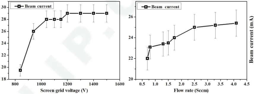
The maximum designed flow rate and grid voltages of our ECRIT are 1.0 sccm and 1500 V, respectively. Figure 3 shows the extraction ion beam current under conditions of different grid voltages and propellant flow rates. The ion beam current increases with the increment of the grid voltages and flow rates at first, and then tends to be constant, which is aligned to the theoretical results.
Figure 3. The extraction ion beam with different grid voltages and propellant flow rates, respectively. And the flow rate is fixed to 1.0 sccm when the voltage varies, while the voltage is set to 900 V as the flow rate changes. The microwave power is 20 W.
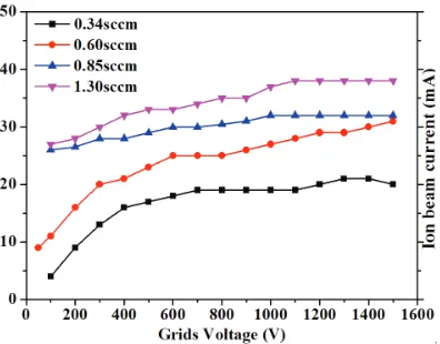
Figure 4. The evolutions of the ion beam current with different grid voltages and propellant flow rates.
Figure 5. The specific impulse and propellant utilization ration with different input microwave power and propellant flow rate.
rate indicating that the propellant pressure is not the major factor for improvement of the thruster performance. Here, the grid voltage is 900 V for the purpose of preventing the arc discharge of the grids with larger propellant flow rate.
In order to further study the effect of propellant flow rate on the performance of the thruster, four levels of the flow rates are tested. The measurement results are plotted in Figure 4. The extraction of the ion beam current increases along with the increment of the Xenon mass flow rate, which is in accordance to the theoretical analysis. In addition, the ion beam current tends to be saturated with the increase of the voltage when the Xenon mass flow rate is greater than a certain value. This is especially remarkable when the flow rates are 0.85 and 1.3 sccm. The saturation voltage is approximately 1200 V. The specific impulse and propellant utilization ratio are measured under four different propellant mass flow rates. The calculation results of the specific impulse and propellant utilization ratio as the input microwave power increases are illustrated in Figure 5. It is significant that both the specific impulse and propellant utilization ratio reach their maximum values when the mass flow rate is 0.6 sccm. However, when the mass flow rate is greater than 0.6 sccm, the specific impulse and propellant utilization ratio decrease as the the mass flow rate increases. This result demonstrates that 0.6 sccm is an optimal value of the mass flow rate for the operation of the thruster. Furthermore, the maximum specific impulse can be up to 4000 s before its saturation at the 40 W of the microwave power.
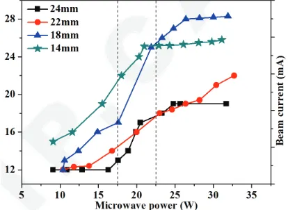
Figure 6. The beam current with two different microwave power stage.
Figure 7. The ion beam current with different microwave power.
microwave power is lower than 20 W. This is attributed to the influence of the relative position of the microwave and magnetic field resonant. However, this phenomenon changes when the microwave input microwave power is greater than 22 W. The beam current strength increases with the increase of the distance at the beginning, and then decreases gradually. The optimal distance between the antenna and the screen grid is around 18 mm. This may be caused by the alteration of the propagate mode of microwave.
Further experiments discover that there is a sharp rise in the narrow power range for the extraction of the ion beam current. The diagnostic results are presented in Figure 7. The mechanism of this beam current transition would be due to the propagation of the microwave in the plasma. At the low-intensity mode, the microwaves are attenuated to enter the discharge chamber from the emission of the antenna. On the other hand, in the high-intensity mode, the microwaves propagate along the plasma-dielectric interface so that the plasma is sustained even in the vicinity of the screen grid. Thus, the higher electron density is expected at higher intensity and larger microwave power [19].
4. CONCLUSIONS
ACKNOWLEDGMENT
This project is funded by Science and Technology on Vacuum Technology and Physics Laboratory, Lanzhou Institute of physics.
REFERENCES
1. Kuninaka, H. and S. Satori, “Development and demonstration of a cathodeless electron cyclotron resonance ion thruster,”Journal of Propulsion and Power, Vol. 14, No. 6, 1022–1026, 2015. 2. Ushio, K., Y. Toyoda, Y. Naoji, T. Morita, and H. Nakashima, “Development of novel miniature
microwave discharge thruster,” IEPC, Vol. 245, 2015.
3. Yuichi, N., T. Daiki, K. Hiroyuki, and K. Komurasaki, “Performance Dependence on microwave frequency and discharge chamber geometry of the water ion thruster,” IEPC, Vol. 454, 2017. 4. Nakamura, K. and K. Hiroyuki, “Three-Dimensional particle simulations of discharge characteristics
for a miniature microwave discharge ion thruster using water as propellant,”IEPC, Vol. 241, 2017. 5. Jin, Y. Z., J. Yang, and M. J. Tang, “Diagnosing the fine structure of electron energy, within the
ECRIT ion source,”Plasma Sci. Technol., Vol. 18, No. 7, 744–750, 2016.
6. Correyero, S. and E. Ahedo, “Measurement of anisotropic plasma properties along the magnetic nozzle expansion of an electron cyclotron resonance thruster,”IEPC, Vol. 347, 2017.
7. Koizumi, H. and H. Kuninaka, “Low power micro ion engine using microwave discharge,” AIAA, Vol. 4531, 2008.
8. Koizumi, H. and H. Kuninaka, “Low power micro ion engine using microwave discharge,” AIAA, Vol. 4531, 2008.
9. Izumi, T., H. Koizumi, and H. Kuninaka, “Performance of miniature microwave discharge ion thruster for drag-free control,”AIAA, Vol. 4022, 2012.
10. Nishiyama, I., T. Tsukizaki, and H. Kuninaka, “Experimental study for enhancement thrust force of the ECR ion thrusterμ10,” AIAA, Vol. 3913, 2014.
11. Yamamoto, N., K. Tomita, N. Yamasaki, T. Tsuru, T. Ezaki, Y. Kotani, K. Uchino, and H. Nakashima, “Measurements of electron density and temperature in a miniature microwave discharge ion thruster using laser Thomson scattering technique,” Plasma Sources Sci. Technol., Vol. 19, 045009, 2010.
12. Lubey, D., S. Bil´en, M. Micci, and P. Taunay, “Design of the miniature microwave-frequency ion thruster,” IEPC, Vol. 164, 2011.
13. Satori, S., A. Nagata, H. Okamoto, T. Sugiki, and Y. Aoki, “New electrostatic thruster for small satellite application,”AIAA, Vol. 3275, 2000.
14. Yang, J., C. Wang, Y. Jin, L. Li, D. Tao, and Y. Yang, “Underlying strain-induced growth of the self-assembled Ge quantum-dots prepared by ion beam sputtering deposition,” Acta Phys. Sin., Vol. 61, 016804, 2012.
15. Sun, A., G. Mao, J. Yang, G. Xia, and M. Chen, “Particle simulation of three-grid ECR ion thruster optics and erosion prediction,” Plasma Sci. Technol., Vol. 12, No. 2, 240–247, 2010.
16. Zhang, H., P. Wang, and J. Qiu, “Study on miniaturized electron cyclotron resonant microwave ion thruster,” Acta Astronautica (in Chinese), Vol. 28, 138–142, 2007.
17. Ke, Y., X. Sun, X. Chen, L. Tian, T. Zhang, and M. Zheng, “Analysis of the primary experimental results on a 5 cm diameter ECR ion thruster,”Plasma Sci. Technol., Vol. 19, 095503, 2017. 18. Boswell, R. and F. Chen, “Helicons-the early years,” IEEE Trans. Plasma Sci., Vol. 25, No. 6,
1229–1244, 1997.