Research on Eccentric Magnetic Harmonic Gear with Halbach Array
Libing Jing* and Jun Gong
Abstract—An eccentric harmonic magnetic gear (EHMG) with Halbacharray is proposed in this paper. According to the theory of magnetic field modulation and one-side effect, the permanent magnets (PMs) on the inner rotor and outer stator are arranged in a Halbach array. The PMs of inner rotor are divided into three segments per pole, and the PMs on the outer stator are divided into two segments per pole. The proposed EHMG with 15 pole pairs on inner rotor PMs and 16 pole pairs on outer stator PMs is established. The finite element analysis (FEA) is used for simulating the proposed model. The corresponding magnetic field and static torque of the EHMG are calculated. Compared with the conventional EHMG, the results show that the torque density of the proposed EHMG is substantially improved.
1. INTRODUCTION
Compared with conventional mechanical gears, magnetic gears (MGs) have many advantages. MG transmits torque or power through the interaction of magnetic fields without mechanical contact. Therefore, MG works with low vibration, low noise, and no lubrication except for ball bearings. MG also features overload protection, which prevents damage to the system [1–3]. In addition, the seamless integration of an MG with a conventional motor enables the MG to have a compact design and high torque density [4–6].
Presently, progress has been made in theoretical and experimental research on MG, and MG has been applied in various fields such as wind turbines [7, 8], electric vehicles [9, 10], and ship propulsion. In recent years, MG can transfer as much torque as mechanical gears. The torque density of the coaxial MG with magnetic field modulation using the modulation ring can be as high as 100 kN·m/m3 [11–14]. In [15], authors proposed and analysed a new coaxial MG using stationary permanent-magnet ring. By quantitative comparison with traditional coaxial MG radially magnetised, it is proved that the coaxial MG can achieve more stable transmission with less torque ripple. In [16], the authors analyzed and calculated the electromagnetic field and the electromagnetic torque of the concentric MG by adopting the exact analytical method, and optimizeds the design of a concentric MG. They offered an effective method for the transmission gear. However, when the transmission ratio is too high, the torque density of these gears tends to decrease significantly. Reference [17] proposed a topological structure of an MG similar to mechanical harmonic gears, which made the inner and outer rotors not coaxial, namely EHMG, which was especially suitable for gear speed ratio greater than 20 : 1. In [18], using the boundary perturbation method, Liu et al. proposed a two-dimensional analytical model of air gap magnetic field of EHMG. The analytical results are compared with the FEA results to verify the correctness of the analytical model. In recent years, some scholars proposed to employ Halbach array to radial modulated magnetic gear [19–21]. In [22], Jian and Chan proposed a coaxial PM with high output torque, which arranged all PMs with Harbach array.
Received 1 November 2019, Accepted 20 December 2019, Scheduled 12 January 2020
* Corresponding author: Libing Jing ([email protected]).
38 Jing and Gong
The results showed that the output torque increased further [22]. Although the EHMG can meet the condition of large transmission ratio, the problem of insufficient torque density still exists. Based on the above research, the Halbach array and EHMG are combined and analyzed in this paper.
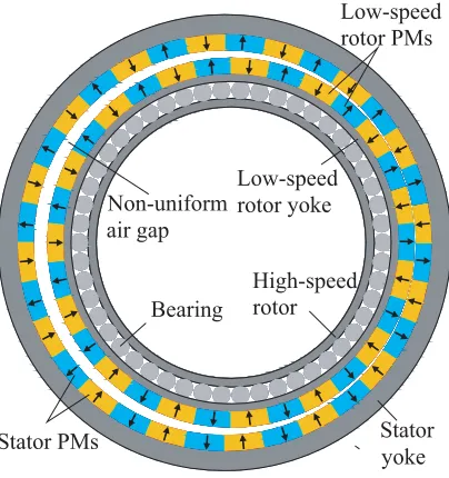
Figure 1 shows the conventional EHMG, which is composed of the stator, low-speed rotor, stator PMs, low-speed rotor PMs, non-uniform air gap, bearing and high-speed rotor.
Non-uniform air gap
Low-speed rotor yoke
Bearing
High-speed rotor
Low-speed rotor PMs
Stator yoke Stator PMs
Figure 1. Conventional EHMG.
In this paper, an analytical model of EHMG with Halbach PM array is established. The proposed EHMG has 15 pole pairs on inner rotor PMs and 16 pole pairs on outer stator PMs. A Halbach array is employed for stator and rotor PMs of EHMG. The FEA will be adopted to analyze the EHMG with Halbach array, and the air gap magnetic field and static torque are calculated and compared with the results of conventional EHMG.
2. OPERATION PRINCIPLE
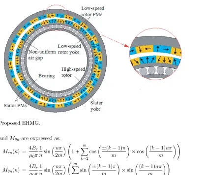
EHMG can be divided into two parts. One part is the stator holding a group of PMs, and the other part is the inner rotor holding a group of PMs. The stator and rotor are of different centers, and the nonuniform air gap is formed in the middle. In order to make the nonuniform air gap change sinusoidal, a high-speed rotor and the inner rotor are sliding in contact. The inner rotor is a low-speed rotor, and the high-speed rotor is equivalent to the harmonic generator of mechanical harmonic gear. The high-speed rotor drives the low-speed rotor to rotate around the stator center. The air gap changes accordingly, and the low-speed rotor rotates around its center at the same time [22]. As shown in Fig. 2, the EHMG with Halbach array is presented.
After employing the Halbach array, the magnetization direction in each permanent magnet segment is given by:
−→
M =Mr−→r +Mθ−→θ (1)
whereMr and Mθ are expressed as:
Mr = ∞
n=1,3,5
Mrn(n) cos(np(θ−θ0)) (2)
Mθ = ∞
n=1,3,5
Figure 2. Proposed EHMG.
whereMrn and Mθn are expressed as:
Mrn(n) = 4Br μ0π
1 nsin
nπ
2m 1 +
m
k=2 cos
±(k−1)π m
×cos (k
−1)nπ m
(4)
Mθn(n) = 4Br μ0π
1 nsin
nπ
2m
m
k=2 sin
±(k−1)π m
×sin (k
−1)nπ m
(5)
where the positive case is for the outer stator; the minus case is for the low-speed rotor;P is the number of pole pairs;m is the number of segments of PMs per pole; kis the kth segments of PMs per pole; θ0 is the initial position angle between the centerline of the PMs and thex-axis of the reference line; Bris remanence; μ0 is the permeability of vacuum.
The air gap of EHMG is sinusoidal periodic change, and the length of air gap changes with the high speed rotor rotation, which can be written in the following form,
g= gmax+gmin
2 +
g
max−gmin 2
×cos(θ−ωht) (6)
wheregmax and gmin are the maximum and minimum airgap lengths, and ωh is the angular velocity of the high-speed rotor. According to [16], the number of pole pairs in the space harmonic flux density distribution produced by the low-speed rotor PMs is given by:
qn,j =np2+ (−1)jp1 n= 1,3,5, . . . ,∞ j= 1,2 (7) According to the results in [16], when n = 1 and j = 2, the amplitude of the magnetic density component corresponding to the number of harmonics is the largest, thus the number of pole pairs on the stator PMs can be obtained. Therefore, the number of pole pairs on the stator PMs is given by:
p3=p1+p2 (8)
where p3 is the number of pole pairs on the stator PMs,p2 the number of pole pairs on the low-speed rotor PMs, andp1 the number of sinusoidal cycles of air gap variation.
In this structure, the number of air gap change cycles is 1, p1 = 1, and the transmission ratio G can be written in the following form,
G=−p1
2
40 Jing and Gong
3. PERFORMANCES ANALYSIS
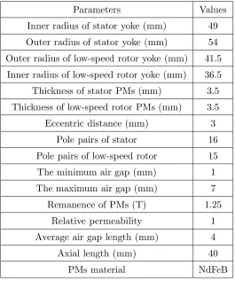
In order to compare the conventional EHMG and proposed EHMG, the parameters of the two EHMGs are chosen to be the same. The specific parameters are shown in Table 1.
Table 1. Parameters of EHMG.
Parameters Values
Inner radius of stator yoke (mm) 49
Outer radius of stator yoke (mm) 54
Outer radius of low-speed rotor yoke (mm) 41.5
Inner radius of low-speed rotor yoke (mm) 36.5
Thickness of stator PMs (mm) 3.5
Thickness of low-speed rotor PMs (mm) 3.5
Eccentric distance (mm) 3
Pole pairs of stator 16
Pole pairs of low-speed rotor 15
The minimum air gap (mm) 1
The maximum air gap (mm) 7
Remanence of PMs (T) 1.25
Relative permeability 1
Average air gap length (mm) 4
Axial length (mm) 40
PMs material NdFeB
3.1. Flux Density Distribution
FEA is used for analyzing the conventional EHMG and the proposed EHMGrespectively. Fig. 3 shows the magnetic field distribution of the two EHMGs. It can be observed that the proposed EHMG exhibits much lower magnetic flux density in both the low-speed rotor yoke and outer stator yoke than that in the conventional EHMG. Therefore, yoke materials can be reduced to achieve the purpose of reducing volume, cost, and weight.
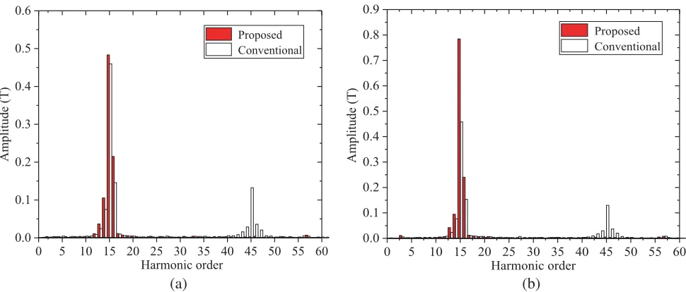
Figure 4(a) shows the radial component of the air gap flux density. Fig. 4(b) shows the tangential component of the air gap flux density.
As can be seen from Fig. 4, it is obvious that the radial flux density of the proposed EHMG is slightly improved compared with the conventional EHMG. In terms of tangential flux density, the proposed EHMG is significantly improved compared with the conventional EHMG.
(a) (b)
Figure 3. Flux distributions. (a) Conventional; (b) Proposed.
Radial flux density (T
)
Electrical angle (degree)
Proposed
Conventional
0 45 90 135 180 225 270 315 360
-1.5 -1.0 -0.5 0.0 0.5 1.0 1.5
Tangential flux density (T
)
Electrical angle (degree)
Proposed Conventional
-1.0 -0.5 0.0 0.5 1.0
0 45 90 135 180 225 270 315 360
(a) (b)
Figure 4. Flux density waveforms. (a) Radial component; (b) Tangential component.
torque, and the 44th and 46th harmonics do not participate in the establishment of the magnetic torque too. After magnetization with Halbach array, almost all of them disappear.
3.2. Static Torque
Static torque is one of the important properties of magnetic gear. According to the Maxwell tensor method, the radial electromagnetic force and tangential electromagnetic force are expressed as follows,
Fr = Lefr 2π
0 1 2μ0
B2
r−Bθ2dθ (10)
Fθ = Lefr 2π
0
1 μ0
BrBθ
42 Jing and Gong
0 5 10 15 20 25 30 35 40 45 50 55 60 0.0
0.1 0.2 0.3 0.4 0.5 0.6
Amplitude (T
)
Harmonic order
Proposed Conventional
0 5 10 15 20 25 30 35 40 45 50 55 60 0.0
0.1 0.2 0.3 0.4 0.5 0.6 0.7 0.8 0.9
Amplitude (T
)
Harmonic order
Proposed Conventional
(a) (b)
Figure 5. Harmonic spectra of flux density in the airgap. (a) Radial component; (b) Tangential component.
0 45 90 135 180 225 270 315 360
-60 -40 -20 0 20 40 60
Torque (Nm)
Electrical angle (degree)
Proposed Conventional
Figure 6. Static torque-angle curve.
The electromagnetic torque of harmonic magnetic gear can be written in the following form:
T = Lefr 2
μ0 2π
0
(BrBθ)dθ (12)
where Lef is the axial length of the EHMG; r is the arbitrary circumference radius with the center of the low-speed rotor as the center in the air gap; Br and Bθ are the radial and tangential components of air gap magnetic density at radius r respectively. When the radius is chosen, r is constant.
4. CONCLUSION
In this paper, an EHMG with a Halbach array has been presented and analyzed. The low-speed rotor and outer stator PMs adopt a Halbach array. The FEA is used for simulating the proposed model. The air gap magnetic field and torque of EHMG with a Halbach array are calculated and compared with the conventional EHMG. Simulation results show that EHMG with a Halbach array can significantly improve the flux density amplitude of air gap. The static torque increases from 22.2 N·m to 48.7 N·m.
ACKNOWLEDGMENT
This work was supported by the National Natural Science Foundation of China (Project No. 51707072), China Postdoctoral Science Foundation (Project No. 2018M632855), and Research Fund for Excellent Dissertation of China Three Gorges University (Project no: 2020SSPY060).
REFERENCES
1. Chen, M., K. Chau, W. Li, C. Liu, and C. Qiu, “Design and analysis of a new magnetic gear with multiple transmission ratios,”IEEE Transactions on Applied Superconductivity, Vol. 3, No. 24, 1–4, 2014.
2. Jing, L. B., L. Liu, M. Xiong, and D. Feng, “Parameters analysis and optimization design for a concentric magnetic gear based on sinusoidal magnetizations,” IEEE Transactions on Applied Superconductivity, Vol. 5, No. 24, 1–5, 2014.
3. Jing, L. B., T. Zhang, Y. Gao, R. Qu, Y. Huang, and T. Ben, “A novel HTS modulated coaxial magnetic gear with eccentric structure and Halbach arrays,”IEEE Transactions on Applied Superconductivity, Vol. 5, No. 29, 1–5, 2019.
4. Park, E. J., S. J. Kim, and S. Y. Jung, “Study on power transmission method of dual-stage type magnetic gear for high transmission ratio,” IEEE CEFC 2016 — 17th Biennial Conference on Electromagnetic Field Computation, 2016.
5. Man, Y., Y. Zhao, and C. Bian, “A kind of magnetic gear with high speed ratio,” Proceedings — 3rd International Conference on Information Sciences and Interaction Sciences, 632–634, 2010. 6. Ruiz-Ponce, G. E., M. A. Arjona, and C. Hern´andez, “Modeling of an axial-type magnetic gear using
a reluctance-based magnetic equivalent circuit,” IEEE CEFC 2016 — 17th Biennial Conference on Electromagnetic Field Computation, 2017.
7. Jian, L. N., K. T. Chau, and J. Z. Jiang, “A magnetic geared outer rotor PM brushless machine forwind power generation,” IEEE Trans. Industry Applications, Vol. 45, No. 3, 954–992, 2009. 8. Colli, V. D., F. Marignetti, and C. Attaianese, “2-D mechanical and magnetic analysis of a 10 MW
doubly fed induction generator for direct-drive wind turbines,” Industrial Electronics Conference, 3863–3867, 2009.
9. Vassilev, A. and A. Ferber, “Magnetic field exposure assessment in electric vehicles,” IEEE Transactions on Electromagnetic Compatibility, Vol. 57, No. 1, 35–43, 2015.
10. Ping, Z., W. N. Wei, and M. Q.Wang, “Investigation of the magnetic circuit and performance of less-rare-earth interior permanent-magnet synchronous machines used for electric vehicles,” Energies, Vol. 10, No. 12, 2017.
11. Jian, L. N., K. T. Chau, and Y. Gong, “Comparison of coaxial magnetic gears with different topologies, magnetic,” IEEE Transactions on Magnetics, Vol. 45, No. 10, 4526–4529, 2009.
12. Li, Y., J. W. Xing, and K. R. Peng, “Principle and simulation analysis of a novel structure magnetic gear,”International Conference on Electrical Machines and Systems, 3845–3849, 2008.
13. Frank, N. W. and H. A. Toliyat, “Gearing ratios of a magnetic gear for marine applications,” Electric Ship Technologies Symposium, 477–481, 2009.
44 Jing and Gong
15. Li, X. L., M. Cheng, and Y. B. Wang, “Analysis, design and experimental verification of a coaxial magnetic gear using stationary permanent-magnet ring,”IET Electric Power Applications, Vol. 12, No. 2, 231–238, 2018.
16. Jing, L. B., Z. H Luo, and L. Liu, “Optimization design of magnetic gear based on genetic algorithm toolbox of matlab,” Journal of Electrical Engineering and Technology, Vol. 11, No. 5, 1202–1209, 2016.
17. Rens, J., K. Atallah, and S. D. Calverley, “A novel magnetic harmonic gear,” IEEE Transactions on Industry Applications, Vol. 46, No. 1, 206–212, 2010.
18. Liu, R. H., L. I. Chen, and Y. J. Zhang, “Analytical model for air-gap magnetic field calculation in an eccentric magnetic harmonic gear,”Proceedings of the Chinese Society of Electrical Engineering, Vol. 33, No. 36, 126–133, 2013.
19. Dogan, N., M. Inci, and A. Bingolbali, “Effects of number of magnet in Halbach magnet system for producing homogeneous magnetic field,” 2015 5th International Workshop on Magnetic Particle Imaging (IWMPI), 2015.
20. Guo, B., Y. Huang, F. Peng, and J. Dong, “An analytical model for axial flux PM machines with Halbach array,” Proceedings of the Chinese Society of Electrical Engineering, Vol. 39, No. 1, 289–295, 2019.
21. Xu, X. Z., Z. Sun, X. D. Wang, H. C. Feng, and B. Y. Du, “Characteristic of a novel PM linear synchronous motor with Halbacharray consequent-pole,” Transactions of China Electrotechnical Society, Vol. 34, No. 9, 1825–1833, 2019.
22. Jian, L. N. and K. T. Chau, “A coaxial magnetic gear with Halbach PM arrays,”IEEE Transactions on Energy Conversion, Vol. 25, No. 2, 319–328, 2010.