Design Techniques used in Microstrip Tri-Band
Bandpass Filter
Sreelekshmi S
Dept. of Electronics and Communication Engineering Adi Shankara Institute of Engineering and Technology
Ernakulam, Kerala, India.
Dr.N.Hariharan
Dean- PG ProgramsAdi Shankara Institute of Engineering & Technology Ernakulam, Kerala, India.
n.hariharan@rediffmail.com
Abstract— Band pass filters play a significant role in the front end of microwave and radio engineering. The rapid progress in wireless communication system has led to an increasing demand for band pass filters with light weight, small size and low loss. Microstrip band pass filters satisfy all these requirements such as light weight, low volume, low power handling, easy fabrication and low loss. For next generation of wireless communication system, multi band filters have become essential requirement. Due to the applications of multi band filters in wireless networks such as wireless local areas networks (WLAN), global system for mobile communication (GSM) and WiMAX, nowadays they have attracted more attention. Tri-band Bandpass Filter (BPF) is one of the critical frontend components in multiband wireless communication systems. In this paper we discussed some design techniques used in the Tri-band Bandpass Filter and also compared the Tri-band Bandpass Filter on the basis of design techniques.
Keywords— Bandpass filter (BPF), applications, microstrip, high selectivity, multi-stub loaded resonator, triple band filter, design techniques
I. INTRODUCTION
In the previous years, wireless communication systems has developed tremendously, there was a prompt development in ultra-wideband systems, wireless internet like WiFi and WiMAX, broadband personal communication systems and 3G (third generation), 4G (fourth generation) technologies. Due to this rapid development there was a need for more rigid microwave components. And now a days satellite systems changed their path from static telecommunications systems to mobile, remote sensing and navigation applications [1]. Microwave components plays an important role in the satellite systems. Microwave components include microwave resonant components such as microwave filters, dielectric resonant antenna arrays (DRA), duplexers. Because of the rapid growth in the wireless communication area, it created more challenging requirements that enforce challenges on various novel designs, optimization and understanding of components. In microwave filters the challenges are to be faced in miniaturization, bandwidth, phase linearity, and selectivity of the filters [14].
A filter is used to regulate the frequency response at a fixed point in the EM spectrum by providing low loss
transmission at the preferred frequency band and high attenuation at remaining frequencies. Filters are extensively used in many applications like communications, remote sensing, radars etc. A filter is generally a two-port network. Filters play an irreplaceable role in virtually any type of radio frequency (RF)/ microwave system today. With the recent rapid development and wide spread use of various wireless communication systems, ever-more stringent requirements are posed on RF/ microwave filters smaller size, higher performance, considered necessary to solve the challenges of insufficient capacity of the various wireless systems [15].
Development of a number of wireless communication standards and devices imposed a requirement for components to simultaneously operate at two or more frequencies that correspond to the standards such as IEEE 806.16, IEEE 806.11, GSM, CDMA, etc. Dual-band bandpass components were the first multi-band circuits to answer this requirement [1]. The first dual-band filter was proposed almost two decades ago, and since then there has been a growing interest in dual band filters. In comparison to dual-band filters, design of bandpass configurations with three or more bands represents a greater challenge when it comes to filter performance and compactness, because good characteristics have to be achieved in three or more closely positioned passbands. In addition to possible signal crosstalk in closely positioned passbands, design of these filters is a demanding task since it requires a steep slope of transfer function. What is more, almost all bands that are commercially used are closely positioned for instance GSM, WLAN, WiFi, WiMAX and UWB systems that operate at 0.9/ 1.8 GHz, 2.4/ 2.45 GHz, 3.5 GHz, and 5.2/ 5.25 GHz.
II. DESIGN METHODS OF MULTIBAND FILTER
Mainly there are three different approaches to the design of multiband bandpass filters, each of which can be divided into sub-groups.
Introducing transmission zeros into the transfer function of a single-band filter represents the simplest method for multi-band filter design. In this section, transmission zeros are due to couplings between non-adjacent resonators. In other words, the structure that forms wide passband also forms transmission zeros. On the other hand, in the method presented here two separate structures are used to obtain passband and stopband, i.e. bandpass and bandstop filters are separately designed [8]. This method is very simple and offers straightforward and efficient realization, this method has been rarely used for multi-band filter design and only dual-band and tri-band filters have been realized using this approach. The reason for this lies in the fact that most aspects do not make this method very favourable in comparison to others. The main advantage of this approach lies in its simplicity.
B. Design by Using Multi-Mode Resonators:
Two filter design approaches were presented and they both have multi-band filters whose passbands cannot be independently controlled and whose dimensions are very large. In this section, a design method that allows more design freedom and filter size reduction will be presented [2]. Filters presented in this section are based on multi-mode multimode resonators. Multi-mode resonators are the structures that support simultaneous propagation of two or more resonant modes whose resonant frequencies are not harmonically related. Therefore, they have been widely used in the design of both single-band and multi-band filters [3].
In single band filters, the resonators used are usually dual-mode, which reduces the number of resonators needed for the realization of the specified filter function. Namely, each dual-mode resonator in a filter provides two closely positioned modes, i.e. transmission poles, and in that manner the number of resonators is reduced by half. As for multi-band filters, multi-mode resonators are used since they can provide passbands or stop bands at frequencies that are not harmonically related.
C. Design by Cascading Independent Single-Band or Dual-Band Filters:
Combining two single band filters to obtain a dual band response, and a single band and a dual-band filter to obtain a response with three or more bands represents the fourth approach to the design of multi-band filters [10]. Since such filters comprise several independent structures, this method gives the most freedom in design in terms of independent control of passbands. Although the configuration, which consists of several structures, may imply large dimensions of filters, some of the most compact multi-band filter circuits with excellent performance have been designed by this method. Design of dual-band filters includes separate design of two single-band filters, which are afterwards put together to form a dual-band filter.
Although the two filters are independent, they influence each other’s performance, and thus the final step in the design is optimization of the geometrical parameters of both single-band filters so as to obtain the desired filter response. Resonators that are used in the design of dual band filters include conventional λ/2 and λ/4 resonators, as well as more complex structures such as dual-mode resonators with perturbation, SIR, and SLR structures.
III. DESIGN TECHNIQUES
A. Tri-Band Bandpass Filter Using Multimode Stub-Loaded Resonator
A Tri-Band Bandpass Filter is designed using stub-loaded resonator (SLR), sharing a common via hole and tapped with 50Ω microstrip transmission lines as shown in Figure 1. The pass bands have been positioned by controlling individual stub lengths and stub widths [2]. The open stubs are coupled with each other because that minimize the circuit size and generate transmission zeros in the stopband. The filter is designed on a 0.762 mm thick Rogers RO4350 substrate with a relative dielectric constant of 3.66 and loss tangent of 0.004. The even- and odd-mode methods can be used to analyze it since the resonator is symmetrical in structure. At the middle as there is no current flow through the symmetrical plane for even-mode excitation to obtain the equivalent circuit. It contains three resonant circuits with having a quarter-wavelength resonator with one end grounded. For odd-mode excitation, there is a voltage null along the middle. This leads to the approximate equivalent circuit, which contains three resonant circuits of having a quarter-wavelength resonator with one end grounded.
Figure 1: Structure of the existing Tri-band BPF
The resonance frequencies (f) of the respective band, even-mode and odd-even-modes can be expressed as
f
odd1=
√ (1)
f
even1=
f
odd2=
√ (3)
f
even2=
√ (4)
f
odd3=
√ (5)
f
even3=
√ (6) The pass band frequencies of a Tri-band filter can be set by properly choosing the even-mode and odd-mode resonance frequencies, which can be set by proper choice of the stub lengths. According to the above analysis, feven1and fodd1 are utilized to form the first pass band (f1) and they are
determined by the length L1, L3, L5 and Ls. These lengths
should be chosen such that they simultaneously satisfy equation (1) and (2) at the respective frequencies (i.e., at the first odd-mode and even-mode resonance frequencies). It may be noted that L3, L5 and Ls also affects other even- and
odd-mode resonance frequencies.
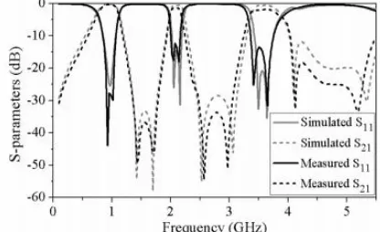
Figure 2: Simulated and measured frequency response of Tri-band BPF
The three passband are located at 0.92, 2.08, and 3.59 GHz, with 3 dB fractional bandwidths of 40.21%, 10.1%, and 16.15%, respectively as shown in Figure 2. The measured insertion losses (IL), including the losses from two SMA connectors in the three passband of the tri-band BPF is found to be 0.41, 1.39, and 1.97 dB respectively. Respective return losses are above 27.7, 12.3, and 16.2 dB. Six transmission zeros are generated at 1.43, 1.69, 2.57, 2.97, 4.12, and 5.19 GHz, with more than 30 dB attenuations, which provide better sharp band-to-band rejection
B. Tri-Layer Tri-Band BandPass Filter Using Hairpin And Spiral Resonators
The Tri-Band filter consists of a pair of quarter wavelength spiral and hairpin resonators and they are connected to the common via which provides the ground connection for the resonators [7]. A pair of uniform impedance resonators are implemented on top layer. The spiral resonators are added on middle and bottom layers respectively as shown in the figure 3. The pass band frequencies can be tuned
independently for desired values by adjusting the geometric parameters of the resonators. The resonators are arranged in Tri-layer structure to reduce the size of the filter.
Five miniaturization methods are utilized for the filter to achieve excellent size reduction.
Method 1: The first method of reducing the size of the filter is using high dielectric constant. The reduction ratio is related to the square root of the relative dielectric constant of the substrate used. Hence the substrate with the higher dielectric constant value results in compact size structure.
Method 2: The second technique is to fold the single layer to form three layer structure. The size of the three layer filter is reduced by more than 50% as compared to the single layer structure. The resonators are divided and arranged in separate layers in multilayer configuration. The main drawback of single layer structure is that the spacing between the resonators cannot be too closed. The strong coupling can be achieved only with smaller gap between the resonators.
Figure 3: (a) Three dimensional view of band filter; Layouts of Tri-Band filter (b) Top Layer (c) Middle Layer and (d) Bottom Layer
This is impossible in single layer structure. Therefore strong coupling effect and size miniaturization can be obtained using multilayer structure. Due to the cross coupling between the resonators in three layers in tri-layer structure, transmission zeros are introduced which in turn improves the selectivity of the filter.
Method 4: The fourth technique is to use rectangular spiral resonators. The two most commonly used spiral resonators are rectangular and circular resonators and both the resonators have similar performance. The advantages of former resonator are efficient utilization of limited area and simple to construct. The spiral resonators offers high quality factor, good power handling, insensitive to fabrication procedures and ultra compact size. The filter utilizing spiral resonator has excellent size reduction as compared to other existing compact filters.
Method 5: The fifth technique is to fold the ends of the hairpin resonators for further size miniaturization. Band pass filters using miniaturized hairpin resonators are 60 smaller in size than those of conventional hairpin filters. To make the filter more compact, the length of the open circuited parallel coupled lines is lengthened to its extremes and separation between the coupled lines is made as small as possible.
Figure 4: Simulated frequency response of Tri-band BPF
The simulated response of Tri-band filter is illustrated in Figure.4. The plot covers a frequency range from 1 GHz to 6 GHz. The simulated response shows that the three pass bands exist at the desired frequencies of 2.4, 3.5 and 5.2 GHz respectively and four transmission zeros. In the first pass band the resonant frequency is at 2.4 GHz with return loss greater than - 4dB and insertion loss lesser than 3dB. In second pass band the centre frequency is at 3.5 GHz the return loss greater than -7dB and insertion loss lesser than 2dB. The return loss is greater than -9dB and insertion loss lesser than 1 dB in the third pass band. Four transmission zeros are realized in the stop band with the stop band attenuation greater than 45dB.
C. Tri-band Filter using Combined E-type Resonators
The structure of the Tri-band BPF using combined E-type resonators consists of a quarter-wavelength (λ/4) stepped-impedance resonator (SIR) and a quarter-wavelength (λ/4) unit impedance resonator through a via hole as shown in Figure 5 (a). These two components are relatively independent. The external coupling is established by a surrounding coupling [13]. The line segments L1, L2 and L3 in conjunction with the
via-hole form a quarter-wavelength resonator as shown in Figure 5 (b).
According to the resonance condition of Yin = 0, this resonant
frequency can be obtained as follows:
f
=
√ (7)Figure 5: (a) Layout of Tri-band BPF (b) Structure of E-type Resonator
Similarly, the two section segments θ1 and θ2 with the
characteristic impedances Z1 and Z2 combined with the
via-hole constitute a SIR (denotes the resonator B). The resonant frequencies can be deduced as:
tanθ1tanθ2 = R (8)
where RZ is the impedance ratio of the SIR and is defined as:
RZ
=
(9)From (7), the second resonant frequency of the proposed resonator could be tuned effectively by adjusting L1, L2 and
L3. That is f2 can be tuned flexibly by adjusting L3, while f1
and f3 keep constant. Correspondingly, from (8), the other two
resonant frequencies (f1, f3) are determined by appropriately
choosing the impedance ratio RZ and length ratio θ of the SIR.
By changing the open stub width W1, the first and the third
passband can be shifted within a wide range, when f2 is fixed.
Therefore, the required three frequencies can be simultaneously obtained.
Figure 6: Simulated and measured results of Tri-band BPF
passbands are 8.5, 3.7, and 3.9%, respectively as shown in figure 6. The minimum insertion losses are 0.46, 1.96 and 1.15 dB, while the return losses of the three bands are below 16.7 dB. The centre frequencies of the three passbands can be independently controlled.
D. Tri-band Filter using six-mode resonator
The structure of the Tri-band BPF as shown in Figure 7. It utilizes the stub-loaded six-mode resonator. A hook-shape feed line is used not only to feed the resonator, but also to create the transmission zeros. To design the Tri-band BPF, the pass-band frequency and bandwidth should be considered. According to the analysis of the even- and odd-mode circuit, the three pass-band frequencies can be controlled individually [1]. To verify the analysis, some simulations are carried out under the condition of weak port coupling. It can be observed that Band 1 and Band 3 change with different L4 and L6,
whereas Band 2 is fixed, and when L3 is changed; only Band 3
is shifted while Band 1 and Band 2 are nearly unchanged. Therefore, the frequencies of the three pass-bands f1, f2 and f3
can be controlled individually. As for the separation of every two modes G4, L7, G3 and L6 should be taken into
consideration. Since G4 and L7 affect the coupling region, all
six modes will therefore be affected by them.
Figure 7. Structure of the Tri-band BPF.
Thus, the design procedures can be summarized as follows. Step 1. According to the required f2 to determine the length
L5 + L7 + L8 which is nearly a quarter-wavelength at f2.
Step 2. Determining the length L4 and L6 according to f1. In
particular, L4 is predominant in controlling f1, while L6 is used for fine tuning.
Step 3. Achieving f3 without affecting f1 and f2 by tuning L3.
Thus, the three center frequencies can be obtained. Step 4. The bandwidth should then be considered. The separation of fodd2 and feven2 can be achieved by
controlling the coupling region of G4 and L7.
Step 5. By tuning L6 and L4, the desired fodd1 and feven1 can be
achieved.
Step 6. G2 is used to obtain fodd3 and feven3.
Finally, fine tuning is used to achieve overall good performance. It should be mentioned that the center frequencies will be slightly shifted when tuning the bandwidths. The overall size of the filter is 13.9mm x 15.9mm. The simulated frequency responses of the Triband Bandpass filter as shown in Figure 8. The three bands are centred at 1.7/3.3/5.3 GHz with the 3dB bandwidth of 11.7/15.1/7.54% that means Band1 is located at 1.7GHz with a 3-dB bandwidth of 11.7% the measure minimum insertion loss is 0.3 dB and return loss is 25 dB. Two transmission zeros are generated at 1 and 2.06 GHz. Band2 is centred at 3.3GHz with 3-dB bandwidth of 15.1%. The minimum insertion loss is 0.2 dB and return loss is 33 dB. The two transmission zeros are generated at 2.06 and 3.8GHz. Band3 has a centre frequency of 5.3GHz with a 3-dB bandwidth of 7.54%. The minimum insertion loss is 0.9 dB and return loss is 34 dB. The two transmission zeros are centred at 5.06 and 5.9.
Figure 8. Simulated results of the Tri-band filter
TABLE I
From this comparison table we can see that Design of Tri-band Bandpass Filter using different design techniques. Here the centre frequency, insertion loss is much better in Tri-band Filter using Six mode Resonators as compared with the other design techniques. This filter have controllable frequencies and bandwidths using a single resonator. Meanwhile, the total size is greatly reduced due to that only one resonator is utilized. This filter used in GSM, WIMAX, GPS applications.
IV. CONCLUSION
In modern wireless communication systems, compact microwave devices capable of operating at more than one frequency band have been developed extensively. Tri-band bandpass filter (BPF) is one of the critical frontend components in multiband wireless communication systems. To minimise the overall size further, a novel compact Tri-band Microstrip Bandpass Filter is designed by using different design techniques has been observed. The characteristics of the Tri-band Filter indicate that the filter is applicable in microwave integrated circuits ensuring high performance in the radio frequency front-end systems, while the wide range of attenuation bandwidth makes it possible to use the filter in microwave satellite and mobile communication systems.
REFERENCES
[1] L. Gao, X. Y. Zhang, B.-J. Hu, and Q. Xue, “Novel multi-stub loaded resonators and their applications to various bandpass filters,” IEEE Transactions on Microwave Theory and Techniques, vol. 62, no. 5, pp. 1162–1172, 2014.
[2] L. Murmu, S. Das, and A. Bage, “A compact tri-band bandpass filter using multi-mode stub-loaded resonator,” in Microwave Conference (APMC), 2016 Asia-Pacific. IEEE, 2016, pp. 1–4.
[3] W.-Y. Chen, M.-H. Weng, and S.-J. Chang, “A new tri-band bandpass filter based on stub-loaded step-impedance resonator,” IEEE Microwave and Wireless Components Letters, vol. 22, no. 4, pp. 179–181, 2012. [4] S. Sachan and R. Chauhan, “Tri band bpf using stub loaded new stepped
impedence resonator,” in Emerging Trends in Electrical Electronics & Sustainable Energy Systems (ICETEESES), International Conference on. IEEE, 2016, pp. 99–101.
[5] J. Liu, F. Liu, B. Ren, P. Wen, Y. Peng, F. Qin, and H. Liu, “Compact tri-band bandpass filter using asymmetric square ring loaded resonator,” in Advanced Materials and Processes for RF and THz Applications
(IMWSAMP), 2016 IEEE MTT-S International Microwave Workshop Series on. IEEE, 2016, pp. 1–3.
[6] Q.-X. Chu and X.-M. Lin, “Advanced triple-band bandpass filter using trisection sir,” electronics letters, vol. 44, no. 4, pp. 295–296, 2008. [7] K. Vidhya and T. Jayanthy, “Design of tri-layer tri-band microstrip band
pass filter using hairpin and spiral resonators,” in Circuits, Power and Computing Technologies (ICCPCT), 2013 International Conference on. IEEE, 2013, pp. 1037–1040.
[8] M. T. Doan, W. Che, and W. Feng, “Novel compact dual-band bandpass filter with multiple transmission zeros and good selectivity,” in Microwave and Millimeter Wave Technology (ICMMT), 2012 International Conference on, vol. 5. IEEE, 2012, pp. 1–4
[9] X. Y. Zhang, Q. Xue, and B. J. Hu, “Planar tri-band bandpass filter with compact size,” IEEE Microwave and Wireless Components Letters, vol. 20, no. 5, pp. 262–264, 2010.
[10] F.-C. Chen, J. Yin, and Q.-X. Chu, “Tri-band filter using single stub loaded resonator,” in Cross Strait Quad-Regional Radio Science and Wireless Technology Conference (CSQRWC), 2012. IEEE, 2012, pp. 96–99.
[11] V. Crnojevi´c-Bengin, Advances in multi-band microstrip filters. Cambridge University Press, 2015.
[12] X. Y. Zhang, J.-X. Chen, Q. Xue, and S.-M. Li, “Dual-band bandpass filters using stub-loaded resonators,” IEEE Microwave and Wireless Components Letters, vol. 17, no. 8, pp. 583–585, 2007.
[13] W. Fan, Z. Li, and S. Gong, “Tri-band filter using combined e-type resonators,” Electronics Letters, vol. 49, no. 3, pp. 193–194, 2013. [14] J.-S. G. Hong and M. J. Lancaster, “Microstrip filters for RF/microwave
applications”. John Wiley & Sons, 2004, vol. 167.