Stability Criteria for Ac Power Systems with Regulated Loads
B.Gouthami & P.Sadanandam
1. M.Tech Student, Vaagdevi College of Engineering, Warangal, India 2. Associate Professor, Vaagdevi College of Engineering, Warangal, India
ABSTRACT
In this paper the voltage source converters are taken for getting the improved d c voltage at the AC source. In the distribution system, power grid is nonideal. with input as voltage source and which consists of some ripples here the power converters or rectifiers are connected to the nonideal grid .interacting with each other .in this paper we are maintains the constant voltage or stable power at the line by using the converters. We consider the effect of
both source (grid) impedance and
transmission line impedance between converters, It is shown that the system of
interacting converters can become
unstable. Moreover, results are presented in design-oriented forms so as to facilitate the identification of variation trends of
stable operation boundaries. The
Experimental results verify in
simulink/MAT LAB.
I.INTRODUCTION
The Power system faces many problems when distributed generation is added in the already existing system; this is because the power system is not designed with distributed generation in mind. The addition of generation could influence power quality problems, degradation in system reliability, reduction in the efficiency, over voltages and safety issues. On the other side’s the power system distribution are well designed which could handle the addition of Generation if there is
Proper grounding, transformers and protection is provided. But there are limits to the addition of distributed generations if it goes beyond its limit then it is important to modify and change the already designed distributed system equipment and protection, which could in a result facilitate the integration of new generation. One of the important aspects is that, power electronic devices and sensitive equipment’s are designed to work in non-polluted power systems. So, they would suffer from malfunctions when the supply voltage is not pure sinusoidal. As these devices are the most important Cause of harmonics, inter harmonics, notches and neutral currents, the power quality should be improved.
capacitors, which regulate the DC bus voltage ripple and store energy for the system. The inverter is composed of insulated gate bipolar transistor (IGBT) semiconductor switches. There are other alternatives to the IGBT: insulated gate commutated thyristors (IGCTs) and injection enhanced gate transistors (IEGTs). This paper will focus on the IGBT as it is used extensively in the MV VSI drives market. The IGBT switches create a PWM voltage output that regulates the voltage and frequency to the motor.
Fig.2 voltage source converter
As the spectrum of applications of VSCs widens, it can be appreciated that multiple VSCs may connect to the power grid at also called common point of coupling (PCC), while each VSC works under its own specific condition, as shown in the usual representationofFig.1.The same structure is also employed in some specific application scenarios, including aircraft power systems, shipboard power systems, micro grid etc. As each converter is designed separately for its own load condition, the mutual coupling in practice via the grid may pose a stability concern as the grid is nonideal in reality and presents at the point of common coupling a significant amount of impedance, which is
not always predictable. As a result, the stability of the system should be considered with the coupled system model in mind rather than the unrealistic though simple model, where each converter is assumed to behave independently.
II.MODEL DISCRIPTION
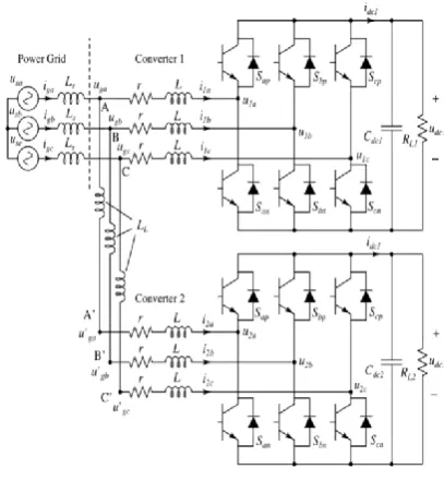
To maintain generality of our study, the VSCs are controlled under a typical feedback configuration that contains an outer voltage loop, which operates in conjunction with a sinusoidal PWM inner current loop for achieving a constant output dc voltage, as presented. The two converters have been designed separately according to their respective application conditions. However, when they are connected to the grid, their interaction may have an impact on stability. Furthermore, in practice, the effect of transmission line impedance LL .
Fig.3. Basic model of two VSCs connected to the nonideal grid.
Have reported the effects of grid impedance on grid-connected interacting converters, but these works focused on the stability of one converter and avoided the complication of analysing the more realistic situation where two or more converters’ interact in the presence of significant grid impedance. While literature abounds with studies of three-phase rectifiers, in-depth study of variation of control parameters on stability of interacting three-phase rectifiers is still glaringly insufficient. Furthermore, from previous study of nonlinear behaviour of power converters, some bifurcation phenomena have been observed and reported, which provide effective analytical tools for some in depth study of stability of interacting converters.
Fig 4.Controller diagram of Simulink file
design-oriented format that reveals the way in which stability would be affected by variation of selected parameters, and hence, facilitates the choice of parameters for stable operation. Moreover, Section V presents the observed instability phenomenon experimentally. Finally, Section VI concludes the paper.
Basic Model: The Standalone Converter Following the formulation of Sun, the three-phase VSC can be represented by an averaged model in the dq rotating coordinate. Since converters 1 and 2 share the same model, we provide, for brevity, the equations for converter 1.
B.ANALYSIS
Literature abounds with conventional methods for analyzing converter’s stability. For an individual grid-connected VSC, control models and their closed-loop stability analysis have been studied, employing techniques like root locus analysis and Bode diagrams. Moreover, the state-space approach is also used to determine stability in the time domain. For grid-connected converters, prior studies have pointed out that the impedance-based approach is more advantageous and flexible. For the case of the grid connected system under study, the impedance-based analysis is highly suitable, as will be demonstrated in the subsequent sections.
Moreover, the two converters may not be connected at the same PCC in practice. Thus, LL =0. When the converters are connected to the same grid at different points of coupling, the presence of nonzero transmission line impedance LL between the two converters’ connection points could
affect stability, as shown in Fig. 5. We see that the two converters connected to the nonideal grid at the same PCC are originally stable, as shown in Fig. 5(a), but can become unstable when the coupling points are separated by nonzero transmission line impedance, as shown in Fig. 5(b). Thus, the converters connected to a nonideal grid can be made unstable by the presence of transmission line impedance separating the points of coupling.
C.THE INSTABILITY
We begin by taking a quick glimpse at the
way in which a
VSClosesstability.ThecircuitofFig.2isstudi edinfullcircuit implementation using MATALAB. The values of the circuit components used in the simulation are summarized in Tables I. Converters 1 and 2 employ the same control method that is described in Fig.. shows stable operation of the two converters with different load
conditions when separately connected to the same nonideal grids with impedance Ls
Hopf-type bifurcation when the values of parameters are selected beyond a specific region in the parameter space (referred to as stability region here)
III.RESULTS AND VERIFICATION
The foregoing analysis provides a precise tool for determining the system’s stability using interface impedance. However, for engineering design purposes, it is more useful to identify the system parameters and their variation trends that have significant impact on the stable region of operation. In this section, we derive stability boundaries using the foregoing analysis and present them in design-oriented forms. Results from simulations of the actual switching circuits will also be presented for
comparison and verification. Relevant to our present study is the region
of stable operation bounded by the bifurcation boundary corresponding to the loss of stability via a Hopf-type bifurcation (practically known as low-frequency oscillation). For the system of two converters connected to a nonideal power grid, we focus on the following conditions
parameters: 1) the grid impedance Ls; 2) the transmission line impedance LL; 3) thedcgainsofthetwoconverters’voltageloop kvp1,kvp2; 4) the converters’ load resistance RL1,RL2; 5) the dc-link capacitance Cdc1,Cdc2.
Moreover, for the purpose of comparison, the stability regions of converters coupled via the power grid and those of the independently operating (uncoupled) converters are presented. Our results are generated from simulations of the complete
switching model, which provides viable verification of the actual physical system.
III.SIMULINK MATLAB MODEL
Fig.5 Simulink model of basic circuit.
IV. RESULTS :
b) Vdc2 Vabc2, & Iabc2
V.CONCLUSION
Three-phase VSCs connected to a nonideal power grid are studied in this paper. This study is important as converters are increasingly being deployed for applications involving power conversion functions that require interfacing with power grid, which is often nonideal. The significant impedance present in the grid poses an issue deserving attention as converters’ stability is no longer a standalone problem. Through mutual interaction, converters become more prone to instability under certain conditions. Analysis has been developed using the impedance approach, and stability boundaries are derived in various parameter planes. Findings reported in this paper would facilitate engineers in making design choices related to the selection of parameter values that would guarantee stability in a sufficiently wide parameter range.
VI.REFERENCES
[1] D. P. Ariyasinghe, and D. M. Vilathgamuwa, “Stability analysis of microgrids with constant power loads,” in Proc. IEEE Int. Conf. Sustainable Energy Technol., 2008, pp. 279–284.
[2] Y.-S. Kim and J.-C. Kim, “Characteristic impedance in low-voltage distribution systems for power line communication,” KIEE J. Electr. Eng. Technol, vol. 2, no. 1, pp. 29–34, 2007.
[3] M. Belkhayat, Stability Criteria for AC Power Systems with Regulated Loads, Ph.D. dissertation, , Purdue University, West Lafayette, IN, USA, Dec. 1997.
and multivariable root loci,” Int. J. Control, vol. 25, no. 1, pp. 81–127, 1977.
[5]S. Vesti, T. Suntio, J. A. Oliver, R. Prieto, and J. A. Cobos, “Impedancebased stability and transient-performance assessment applying maximum peakcriteria,”IEEETrans.PowerElectron.,v ol.28,no.5,pp.2099–2104, May 2013.
[6] M. Belkhayat, R. Cooley, and E. Abed, “Stability and dynamics of power systemswithregulatedconverters,”inProc.IE EEInt.Symp.CircuitsSyst., May 1995, vol. 1, pp. 143–145.
[7] L. Harnefors, M. Bongiorno, and S. Lundberg, “Input-admittance calculation and shaping for controlled voltage-source converters,” IEEE Trans. Power Electron., vol. 54, no. 6, pp. 3323–3334, Dec. 2007.
[8] M. C´espedes and J. Sun, “Impedance shaping of three-phase grid-parallel voltage-source converters,” in Proc. IEEE Appl. Power Electron. Conf., Feb. 2012, pp. 754–760.