Finite Element Analysis of Micro End Mill & Simulation of Burr
Formation
Pilli Sailendra & Mrs. Aseena Shaik
M.Tech (MECH), Department of Mechanical Engineering, Helapuri Institute of Technology and Science, Eluru, A.P.
Assistant Professor, Department of Mechanical Engineering, Helapuri Institute of Technology and Science, Eluru, A.P.
ABSTRACT:
In this undertaking, temperature at instrument tip interface is resolved, produced in fast machining activities. In particular, three distinct examinations are contrasting with a test estimation of temperature in a machining procedure at moderate speed, medium speed and at fast. What's more, three examinations are done of a High Speed Steel and of a Carbide Tip Tool machining process at three diverse cutting paces, with a specific end goal to contrast with exploratory outcomes delivered as a feature of this investigation. An examination of warmth age in cutting instrument is performed by fluctuating cutting parameters at the appropriate cutting apparatus geometry. The trial comes about uncover that the primary elements in charge of expanding cutting temperature are cutting pace (v), nourish rate (f), and profundity of cut (d), separately. It is likewise established that adjustment in cutting pace and profundity of cut has the most extreme impact on expanding cutting temperature. Different looks into have been embraced in estimating the temperatures created amid cutting tasks. Examiners made endeavor to quantify these cutting temperatures with different procedures amid machining. In this venture, "Fluke 62 max IR thermometer" (Range - 40 0C to 650 0C) is utilized for estimating temperature at apparatus tip interface. Single
point cutting apparatus has been strong demonstrated by utilizing CAD Modeler Siemens 8.0 and FEA did by utilizing ANSYS Workbench 14.5. Exploratory work is at "S.V.P Engineering" . By differing different parameters the impact of those on temperature are contrasted and the exploratory outcomes and FEA comes about. Watchwords: Multi Point Cutting Tool (carbide) device and Carbide tip instrument (P - 30), Computer Aided Design (CAD), processing , Fluke 62 max IR thermometer (Range - 40 0C to 650 0C ), Finite Element Analysis, Solid Modeling.
INTRODUCTION:
symmetric and have different highlights, for example, openings, spaces, pockets, and even three dimensional surface forms. Molded surfaces, which incorporate rack and round riggings, circles, helical, ratchets, sprockets, cams, and different shapes, can be promptly cut by utilizing processing task. As of late, small scale processing process has increased tremendous prevalence because of market necessities and innovative progressions which has prompt manufacture and utilization of smaller scale structures. It has a few focal points like usability, ability to create complex three dimensional geometries, process adaptability, low set-up cost, extensive variety of machinable materials and high material expulsion rates. This part builds up the foundation for the present work and talks about the need to take up this work. It exhibits a survey of accessible significant writing. Targets of the present work alongside procedure received to achieve them are likewise talked about here.
Problem Definition
This work is an attempt to optimize micro milling tool parameters for minimization of micro burrs formed during micro machining. The objectives of this work are stated as follows:
To develop three-dimensional solid models of multi point milling cutters.
To perform the static finite element analysis of the tools during milling.
To perform the finite element detailed analysis of the tool and work piece combination during milling.
To perform burr formation simulation in milling
LITERATURE SURVEY
C. BetegonBiempica et al (2007), the aim of this paper is to study the residual stresses in an UIC-60 rail and their reduction by means of roller straightening. Both experimental and numerical investigations have been carried out in the past to reveal the formation of dominant longitudinal residual stresses. However, the agreement between both investigations was not particularly good. The finite element method (FEM) has also been used to simulate one, two and three-dimensional analyses of a rail during roller straightening processes. The present model considers the longitudinal movement of a rail through the straightening machine, contact conditions between rail and rollers and kinematic hardening so as to take into account the plastic behavior of the rail material (steel). These results were compared with the experimental investigations and good agreement was observed. In this respect, this paper presents a novel, more realistic numerical simulation by FEM for the roller straightening process. Finally, an improvement of the straightening process in order to obtain smaller residual stress in the rail section is proposed.
are to be achieved The present work involves the study of tool wear caused by the change in hardness of single point cutting tool for a turning operation to predict the tool life in orthogonal cutting based on the heat transfer analysis using Finite Element Method (FEM). The Experiments 19 were performed with EN-24 steel as work piece and Carbide uncoated tool bit as a tool material and the flank wear has been measured experimentally. An empirical relation is used to determine temperature at tool-tip and further Finite Element Method is used to determine the distribution of temperature over the surface of tool and its impact on hardness which is related by an empirical relations. The study shows the effect of Modified temperature due to strain rate on carbide tool to describe the thermal softening of tool material and becomes prone to wear. The results reveal that by increasing process variables in machining the wear and temperature increases causing thermal softening of tool causing it to wear. The results obtained have been verified with the available results from literature for the variation of wear with the temperature and thermal softening of carbide tool. The results prescribed demonstrate the significance of cutting parameters (speed, feed and depth of cut) in thermal analysis for study of the cutting tool wear.
3. FINITE ELEMENT ANALYSIS
PC supported building (CAE) is the use of PC programming in designing to assess segments and congregations. It incorporates reenactment, approval, and improvement of items and assembling instruments. The essential use of
CAE, utilized as a part of common, mechanical, aviation, and electronic building, appears as FEA close by PC helped outline (CAD).
3.1 Finite component examination
All in all, there are three stages in any PC supported designing errand:
• Pre-handling – characterizing the limited component show and natural elements to be connected to it
• Analysis solver – arrangement of limited component demonstrate
• Post-handling of results utilizing perception devices
3.1.1 Pre-handling
system to accomplish demonstrating similitude in basic examination is to use prior advanced outlines, plan documents, CAD models, as well as information by bringing in that into a FEA domain. Once the limited component geometric model has been made, a cross section strategy is utilized to characterize and separate the model into little components. When all is said in done, a limited component show is characterized by a work organize, which is comprised of the geometric game plan of components and hubs. Hubs speak to focuses at which highlights, for example, relocations are figured. FEA bundles utilize hub numbers to fill in as an ID device in review arrangements in structures, for example, avoidances. Components are 16 limited by sets of hubs, and characterize restricted mass and solidness properties of the model. Components are additionally characterized by work numbers, which enable references to be made to relating avoidances or worries at particular model areas.
3.1.2 Analysis (calculation of arrangement)
The following phase of the FEA procedure is investigation. The FEM conducts a progression of computational methodology including connected powers, and the properties of the components which create a model arrangement. Such an auxiliary examination permits the assurance of impacts, for example, distortions, strains, and stresses which are caused by connected basic loads, for example, power, weight and gravity.
3.1.3 Post-preparing (perception)
These outcomes would then be able to be examined utilizing perception instruments inside the FEA condition to see and to completely distinguish ramifications of the examination. Numerical and graphical devices permit the exact area of information, for example, stresses and redirections to be recognized.
3.2 Applications of FEA to the mechanical designing industry
applications. The presentation of FEA has considerably diminished the time taken to take items from idea to the creation line. It is fundamentally through enhanced introductory model outlines utilizing FEA that testing and advancement have been quickened. In outline, the advantages of FEA incorporate expanded exactness, improved plan and better knowledge into basic plan parameters, virtual prototyping, less equipment models, a quicker and more affordable plan cycle, expanded profitability, and expanded income.
3.3 Computer-helped plan and limited component investigation in industry
The capacity to show a basic framework in 3D can give an intense and exact examination of any structure. 3D models, when all is said in done, can be delivered utilizing a scope of basic PC supported plan bundles. Models tend to go to a great extent in both many-sided quality and in record arrange, contingent upon 3D display creation programming and the multifaceted nature of the model's geometry. FEA is a developing industry in item outline, investigation, and improvement in designing. The pattern of using FEA as a designing apparatus is developing quickly. The headway in PC handling force, FEA, and demonstrating programming has permitted the proceeded with joining of FEA in the building fields of item outline and improvement. Previously, there have been numerous issues limiting the execution and at last the acknowledgment and use of FEA in conjunction with CAD in the item plan and improvement stages. The holes in similarity between CAD
record configurations and FEA programming constrained the degree to which organizations could undoubtedly outline and test their items utilizing the CAD and FEA blend, separately. Commonly, architects would utilize expert CAD and displaying programming in the outline of the item and after that desire to trade that plan into a FEA bundle to test. In any case, those architects who relied upon information trade through custom interpreters or trade gauges, for example, IGES or STEP refer to intermittent unwavering quality issues causing unsuccessful trade of geometry. Consequently, the formation of numerous models outside to FEA situations was thought to be dangerous in the accomplishment of FEA. The present pattern in FEA programming and industry in designing has been the expanding interest for reconciliation between strong demonstrating and FEA examination. Amid item plan and advancement engineers require programmed refreshing of their most recent models amongst CAD and FEA conditions. There is as yet a need to enhance the connection amongst CAD and FEA, making them actually nearer together. Be that as it may, the interest for unitary CADFEA incorporation combined with the enhanced PC and programming improvements has presented a more hearty and community drift where similarity issues are starting to be dispensed with. Fashioners are currently starting to present PC reenactments equipped for utilizing prior CAD records, without the need to alter and reproduce models to suit FEA conditions.
Different yields and attributes of the metal cutting procedures, for example, cutting powers, stresses, temperatures, chip shape, and so on can be anticipated by utilizing FEM without doing any analysis.
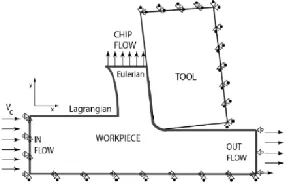
3.4.1 Lagrangian technique Lagrangian definition is utilized primarily in issues on strong mechanics. In this, the work moves and contorts with the material being displayed because of powers from neighboring components. It is profoundly preffered when stream of material included is unconstrained. Limits and chip shape require not be known heretofore. Recreation of spasmodic chips or material crack should be possible by utilizing chip partition criteria in metal cutting models in view of Lagrangian detailing. In any case, metal being endures extreme plastic misshapening and mutilation happens. Work recovery is in this manner required. Chip detachment criteria additionally should be given.
3.4.2 Eulerian technique In Eulerian detailing, the FE work is settled spatially, which enables materials to spill out of one component to the following. Plus, less components are required for the examination, which lessens the calculation time. In any case, assurance of the limits and the chip shape should be done before the recreation. Additionally amid the examination, the apparatus chip contact length, the contact conditions between instrument chip and the chip thickness, must be kept consistent
3.4.2.1 Arbitrary Lagrangian-Eulerian (ALE) strategy Arbitrary Lagrangian-Eulerian (ALE) joins the best highlights of Eulerian and Lagrangian definitions. In ALE detailing, the material stream is taken after and Langrangian step is utilized to tackle removal issues, while the work is repositioned and Eulerian step is utilized to take care of speed issues. Eulerian approach is utilized for displaying the apparatus tip region where cutting procedure happens. Thus, without utilizing remeshing, extreme component mutilation is maintained a strategic distance from. Lagrangian approach is utilized for the unconstrained material stream at free limits.
Figure 1.3: Eulerian and Lagrangian boundary conditions in ALE simulation
3.5 Development of Three Dimensional CAD model
Method involved in the design of a cutter includes:
Creation of cross-sectional profile of the tool and helix generation
Flute creation using slot operation
Creation of back surface of the tool
Cutting edge generation
Parameters involved in generating the cross sectional profile are:
Relief angle of the tool
Tool diameter
Number of flutes
Parameters involved in modeling the helix are:
Height of the tool
Diameter of the tool
Pitch of the helix
Helix angle of the tool
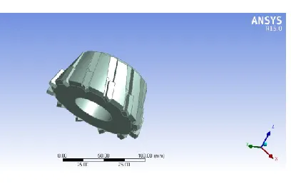
The three dimensional CAD models of both the flat end mills was produced by performing ansys work bench
`
CAD MODEL OF THE TOOL
Figure below shows the meshed model of the multi point cutting tool.
2D triangular mesh was used for analysis or 3d tetrahedron mesh was generated.
MESH REPORT
Model (A4) > Mesh
Object Name Mesh
State Solved
Defaults
Physics Preference Mechanical
Relevance 0
Sizing
Use Advanced Size Function Off
Relevance Center Coarse
Element Size Default
Initial Size Seed Active Assembly
Smoothing Medium
Transition Fast
Span Angle Center Coarse
Minimum Edge Length 4.306e-002 mm
Inflation
Use Automatic Inflation None
Inflation Option Smooth Transition
Transition Ratio 0.272
Maximum Layers 5
Growth Rate 1.2
Inflation Algorithm Pre
View Advanced Options No
Triangle Surface Mesher Program Controlled
Patch Independent Options
Topology Checking Yes
Advanced
Number of CPUs for Parallel Part Meshing
Program Controlled
Shape Checking Standard Mechanical
Element Midside Nodes Program Controlled
Straight Sided Elements No
Number of Retries Default (4)
Extra Retries For Assembly Yes
Rigid Body Behavior Dimensionally Reduced
Mesh Morphing Disabled
Defeaturing
Pinch Tolerance Please Define
Generate Pinch on Refresh No
Automatic Mesh Based
Defeaturing On
Defeaturing Tolerance Default
Statistics
Nodes 10325
Elements 5562
Mesh Metric None
Meshed Model
Boundary conditions
The displacements of X, Y and Z directions are zero at the upper surface and the center hole, Mz at the upper surface of 100nm is applied.
Static and dynamic analysis is carried out for two materials, stresses deformations and mode shapes have been extracted.
MATERIAL PROPERTIES [17]
The table shows the material properties of two materials used, High speed steel and AL6061
Materials HSS AL6061
Density (kg/m3) 7980 12100
Young’s modulus, E (GPa)
210 558
Chemical composition of HSS in percentages
Molybdenum high-speed tool steels (M7) UNS Designation- T11307
Chemical C Si Cr V W Mo
Compositi on
1.0 1
0.3 8
3.7 5
2.0 0
1.7 5
8.7 0
RESULTS AND DISCUSSIONS
4.1 STATIC ANALYSIS WITH HSS MATERIAL
The figure shows the total deformation of the tool under the moment applied for High Speed Steel material, Maximum deformation was observed at the top face of the tool with magnitude of 0.00035.
Total Deformation of the tool for HSS material
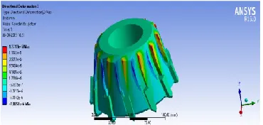
The figure below shows the variation of Directional Deformation along X axis in mm, The maximum deformation of magnitude 0.000343mm was observed.
Deformation along X Axis for HSS material tool
The figure below shows the variation of Directional Deformation along Y axis in mm, The maximum deformation of magnitude 0.000342mm was observed.
Deformation along Y Axis for HSS material tool
The figure below shows the variation of Directional Deformation along Y axis in mm, The maximum deformation of magnitude 3.82 e-05 mm was observed.
Deformation along Z Axis for HSS material tool
Equivalent Stress for HSS material
The below figure shows the stress intensity observed on the tool during rotaion. Maximum of 10.932Mpa was found on the top face of the tool.
Stress Intensity for HSS Tool
Figure shows the variation of strain intensity for the tool ,maximum of 6.76e-5mm/mm was observed at the top face, this is very less magnitude and thus the tool will be able to withstand more deformation
Elastic strain Intensity for HSS material
4.2 STATIC ANALYSIS OF TOOL WITH AL6061 MATERIAL
The figure shows the total deformation of the tool under the moment applied for AL6061 material, Maximum deformation was observed at the top face of the tool with magnitude of 0.00012.
Total Deformation of the tool for AL6061 material
The figure below shows the variation of Directional Deformation along X axis in mm, The maximum deformation of magnitude 0.000121mm was observed.
Deformation along X Axis for AL6061 material tool
maximum deformation of magnitude 0.00012mm was observed.
Deformation along Y Axis for AL6061 material tool
The figure below shows the variation of Directional Deformation along Y axis in mm, The maximum deformation of magnitude 1.37 e-05 mm was observed.
Deformation along Z Axis for AL6061 material tool
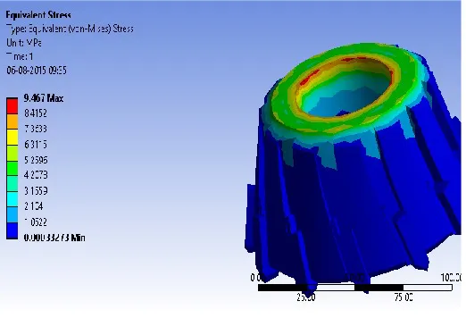
The figure shows the variation of equivalent or Von misses Stress under the moment applied, maximum of 9.5Mpa was found. The von-misses stress was under the material yield strength and hence can withstand the load.
Equivalent Stress for AL6061 material
Figure shows the variation of stress intensity for the tool, maximum of 10.99Mpa was observed at the top face, this is very less magnitude and thus
the tool will be able to withstand more deformation
Stress Intensity for AL6061 material Tool
RESULTS COMPARISONS
Comparison of Total Deformation for AL6061 and HSS
Comparison of Equivalent Stress for AL6061 and HSS
0 0.0001 0.0002 0.0003 0.0004
Total Deformation(mm)
Total Deformation( mm)
9.4 9.45 9.5 9.55
Equivalent Stress Mpa
Comparison of Stress intensity for AL6061 and HSS
CONCLUSIONS AND FUTURE SCOPE
From the results obtained in ANSYS it can be observed that the deformation for HSS material tool is more than the AL6061 tool by approximately 85%.This is due to the high density of AL6061.
Equivalent stress observed for AL6061 tool is more than HSS material tool
Stress intensity for the AL6061 material multi point tool is more than the high speed steel tool
From the results the fail safe condition for the tool has been established by comparing with the practical data
AL6061 material can be used for the tool when the force required for the milling process is more.
FUTURE SCOPE
The analysis can be carried out with different rotational speeds, under varing load and for different materials other then the materials used in this thesis
10.9 10.92 10.94 10.96 10.98 11
Stress Intensity