* Corresponding author: r-piter@yandex.ru
MECHANICS OF MAGNETIC FLUID ACTIVE ELEMENT IN
STRONG MAGNETIC FIELD
Polunin V.M.1, Ryapolov P.A.1, Sheldeshova E.V.1 1 Southwest State University, Kursk, Russia
Abstract. Measurements and theoretical analysis of the processes of static displacement and oscillations of the magnetic fluid column confined by magnetic levitation in a strong magnetic field in a horizontally placed tube are carried out. The calculations of the saturation magnetization, made on the basis of the obtained results of the displacement and the oscillation frequency for the sample of the magnetic fluid under study, are in good agreement with the experimental data. The described technique is of interest when studying saturation magnetization, magnetophoresis, aggregation of nanoparticles and their temporal dependence in magnetic colloids.
1 INTRODUCTION
The design of many devices using magnetic fluids MF is based on the impact of inhomogeneous magnetic field, i.e., ponderomotive force, on the drop of magnetic colloid; this can be observed while the drop displaces from equilibrium position. Such devices can be called oscillatory systems, wherein MF acts as an inertial-viscous element [1-4]. The most common oscillation systems based on nanodispersed MFs, such as controlled shock absorbers and vibration damping complexes, acoustic dynamics with the use of MF, are based on linear vibrations of MF elastic elements on the basis. Therefore, of particular interest are measurements of the elastic-magnetic parameters of a magnetic fluid held by magnetic levitation, in which linear movements of the MF sample are tracked.
2 EXPERIMENTAL SETUP
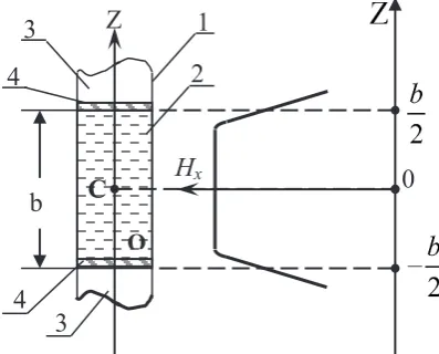
To measure MF-column displacement in a strong magnetic field under hydrostatic pressure an experimental setup, the diagram of which is presented in figure 1 was designed.
In the experiment, we used a laboratory electromagnet FL-1 with a diameter of the pole tips equal to 100 mm. The construction of the electromagnet FL-1 and its specifications are given in [5]. The transparent tube 1 made of plexiglas with the internal diameter d = 12 mm is fixed between the pole tips. The tube axis passes horizontally through the centre of the pole gap and is parallel to the surface of the pole tips. When the magnetic field intensity is ≥ 100 kA/m, the tube is filled with a magnetic fluid 2, which is captured by the field and holds in the region of high magnetic field. The position of the tube is fixed with the holding device. In
the initial state, MF-column is symmetric with respect to the pole centre. One end of the tube using a silicone tube 3 is connected with the U-shaped tube 4 filled with distilled water. The U-shaped tube elbows are of 800 mm, its internal diameter is 16 mm. The difference in water levels Δh in the tube elbows is determined using cathetometer.
To measure MF-column displacement under hydrostatic pressure – Δz on the same plane with the horizontal axial section of the tube the reference mark is made as it is shown dashed in figure 1; a camera was placed above the whole system to record data of MF-column boundary
displacement. MF-column moves to equilibrium state due to the resultant action of ponderomotive force and hydrostatic pressure.
The diagram of the experimental setup for measuring MF-column oscillation frequency ν is shown in Figure 2. There are some new parts in this setup in comparison with the setup shown in Figure 1. The piston 3 is used to drive oscillations. There is a fine air gap between the piston and magnetic fluid. The oscillation indicator, the inductance coil 4 is mounted in the gap between the tube and the pole tip at the level of MF-column free surface. The inductance coil has 5,000 turns of copper wire with a diameter of 0.071 mm wound around the Plexiglas spool. The signal from the oscillation indicator comes to Selective Nanovoltmeter type 237 5. After amplification, the signal is transmitted to GwInstek GOS-72074 oscillograph 6, and then to a computer (not shown in Figure 2) for further processing.
Figure 3. The computational pattern
С
О
1
2
3
4
4
3
b
0
Z
H
хFig. 1. Static experimental setup diagram 4
1 2 3
Fig. 2. Dynamic experimental setup diagram 3
5 6
4
1 2
The experimental dependence of magnetic field intensity (to be more precise, its component Hx) on the z coordinate along the OZ axis extending from the centre of the pole gap parallel to the surface of the pole tips were measured. The measurements were carried out in the range of magnetic field intensity from 100 kA/m to 900 kA/m in increments of 50 kA/m. The teslameter probe moves over the distance of 90 mm using cathetometer. The probe position at the distances from 0 mm to 40 mm and from 70 mm to 90 mm is set at a pitch of 10 mm, and at the distance of 40 mm to 70 mm it is set at a pitch of 2 mm is fixed with an accuracy of 0.01 mm. The values of the magnetic field intensity peculiar to MF-column top and bottom are marked with the
dashed line. A significant feature of the obtained dependencies Нx(z) is the presence of a linear segment on the curves at the level of z = 57.5 mm, which allows us to take the magnetic field intensity gradient at this segment as follows: Hx/ z const
The measurements of physical quantities ν, Δh, and Δz are made at fixed magnetic field parameters. Table 1 shows the used combination of magnetic field parameters: H0, which is magnetic field intensity in the
centre between the poles of the electromagnet, H*,
which is magnetic field intensity, and ΔНх/Δz, which is the magnetic field intensity gradient.
Table 1
H0,
kA/m kA/m H*, ΔНMA/mх/Δz, 2
200 156 3.42
300 236 5.13
400 313 6.95
500 391 8.7
600 469 10.5
700 540 12.4
800 619 14.2
900 686 15.9
In a strong and inhomogeneous magnetic field, MF-column takes a form close to a cylindrical one; in the conducted experiment, the distance between the bases of the cylinder is 115 mm.
3
THEORY OF MF-COLUMN
ELASTOMAGNETIC PROPERTIES
The computational pattern introduced for solving the task is shown in Figure 3. It is assumed that the MF left and right free surfaces are on the linear segments of the magnetic field decrease.
For the elasticity coefficients of this system, the following values of the elasticity coefficients were obtained in [6]:
For the static experiment the hydrostatic coefficient determined by the water pressures in the U-shaped manometer:
2 / 4
s w
k d g h z, (1)
where w is the water density.
The ponderomotive coefficient is determined by the magnetic fluid displacement from the equilibrium position: 2 0 /2 2 x p x z b H d k M z
, (2)
For the dynamic experiment the coefficient is determined from the oscillation frequency:
2 2/ 4
d
k bd (3)
where is the MF density.
The ponderomotive coefficient is determined by the magnetic fluid displacement from the equilibrium position with addition to viscous friction:
2 2
3 0
/2
2 2 2
x
d x
z b
H d
k M bd
z
(4)
We studied a sample of finely dispersed magnetite-based magnetic fluid – Fe3O4 which is stabilized by a
surfactant – oleic acid С8Н17СН=СН(СН2)7–СООН.
Undecane C11H24, an alkane hydrocarbon, was used as
the dispersion medium – liquid carrier. The Undecane fluid MF-1 was synthesized in Ivanovo State Power Engineering University.
Figure 4 shows MF-column elastomagnetic parameters in the strong magnetic field which include oscillation frequency ν, elasticity coefficients ks, kd, kdω,
kp and the correction for viscous fluid flow calculated
using formulas (1), (2), (3), (4) depending on the magnetic field intensity gradient. The calculations were performed using the experimental results: by measuring the MF-column oscillation frequency; the data obtained by measuring the magnetic field intensity gradient at the MF-column base, static measurements of the water column level differences in the elbows of the U-tube Δh and Δz – MF-column displacement under hydrostatic pressure. In this case, the calculations of kd were
performed using the values of Mx belonging to the
magnetization curve of the sample under study.
As it can be seen from the data shown in Figure 4, the elasticity coefficients kp, ks and kd, kdω corrected for
the viscous fluid flow are approximately equal to each other to each other. Thus, we got an experimental confirmation of the above assumptions concerning the presence of equality, and we can obtain the value of the magnetization from two experiments:
magnetostatic saturation magnetization, which is obtained from (2) for the static displacement of the magnetic fluid horizontal column from equilibrium position.
0
2w
SS g s
M tg
magnetodynamic saturation magnetization, which is obtained from (3) for magnetic fluid dynamic oscillations, taking into account viscous magnetic fluid flow. 2 0 2 Sd d M tg d
To test the sensitivity of the proposed method to the change in the structure of the magnetic fluid, these fluids were modified. The sample MF-2 was partially evaporated from the sample MF-1. The physical parameters of the samples are shown in Table 2
3 7
0 20 40 60 80 100 120 140 160
k, N/m,
ν, Hz
5 9 11 13 15 17
180
ΔН/Δz,∙MA/m2
Figure 4. Parameters of oscillation system ■ - ν, ○ - , ●- , △- kd, □ - kp, ▲- ks depending on the magnetic
Table 2
Sample MF-1 MF-2
Carrier fluid Undekan
Modification Evaporation of carrier fluid ρ, kg/m3 1227 1240
φ, % 10,8 11,1
χ 1,6 2,1
Ms, kA/m 40,4 45,1 M
SS, kA/m 40,9 46,2
M
Sd , kA/m 40,6 45,8
The magnetization curves obtained for liquids based on undecane are presented on the figure 5. The rhombus is a ballistic method, rectangles are the magnetodynamic method.
It can be seen that the data of the two methods are in good agreement. But for a structured magnetic fluid MF-2, the difference between the data of the two methods is greater. Data presented in Table 2 show that a small change in the nanoparticle volume fraction ‘phi’ (from 10.8 to 11.1%) seems to produce an unproportionnally strong increase in saturation magnetization (from about 41 to about 46 kA/m). This can be explained by the fact that when magnetic fluid is evaporated, a structure is formed in it.
4 CONCLUSIONS
The following results were obtained: the construction and validation of the model theory of elasticity formation
of MF in a tube confined by magnetic levitation in a strong magnetic field were carried out, the described technique of complex measuring MF elasticomagnetic parameters in the strong magnetic field is of interest when studying magnetophoresis and aggregation of nanoparticles in magnetic colloids.
The research was carried out as a part of the project of state assignment of the Ministry of Education and Science of the Russian Federation. Project code: 3.2751.2017/PP.
References
1. Bogdan Sapinski. Of MR Fluids Recommended For Use In Shock Absorbers / Bogdan Sapinski, Wojciech Horak. Rheological Properties // acta mechanica et automatica, vol.7 no.2 (2013).p.107-110.
2. Bashtovoi, V.G. The effect of magnetophoresis and Brownian diffusion on the levitation of bodies in a magnetic fluid / Bashtovoi V.G., Polevikov V.K., Suprun A.E. // Magnetohdrodynamics. 2008. Vol. 44. №2. P. 121-126.
3. Boev M. L., Polunin V.M, P.A. Ryapolov, [et al.] Instability of the Flow of a Magnetic Liquid Pushing Down an Air Cavity // Russian Physics Journal. 2015. V. 57. №10. pp 1348-1355
4. Polunin V. Acoustics of nanodispersed magnetic fluids. New York- London: CRC Press, CISP, 2015. Р. 472
5. Chechernikov V.I. Magnetic measurements. - M.: MGU, 1969. 387 p.
6. Polunin V. M., Ryapolov P. A., Platonov V. B., and Kuz’ko A. E. Free Oscillations of Magnetic Fluid in
10 0 20 30 40 50
0 200 400 600 800 1000
М, kA/m
Н, kA/m
Figure 5. The magnetization curves for MF-1 (a) and for MF-2 (b) a)
b)
0 10 20 30 40 50
М, kA/m