www.ijiset.com
Design and Development of Low Cost Compact Force
Dynamometer for Cutting Forces Measurements and Process
Parameters Optimization in Turning Applications
Muhammad Imran Hanif *1, 2, Muhammad Aamir1, Riaz Muhammad1, Naseer Ahmed1, Shahid Maqsood 2
1
Mechanical Engineering Department, CECOS University of IT & Emerging Sciences, Peshawar, Pakistan
2
Industrial Engineering Department, University of Engineering & Technology, Peshawar, Pakistan
*Corresponding Author: email: [email protected]
Abstract
Cutting forces plays a vital in machining process as they provide useful information not only for the work done but also for understanding the mechanics of machining process .On the other hand the heat generated during machining process has a direct influence on cutting forces therefore accurate measurement of cutting forces in turning is essential for tool material and geometry and selection of proper cutting parameters. Available commercial dynamometers cover a wide range of machining applications but there is a lack of force measuring devices capable for cutting forces in turning process with comparatively high spindle speeds under dry cutting conditions, In this work, the development and testing of an innovative tool shank type strain gauge based force dynamometer designed for high speed turning is discussed. The orientation of strain gauges was set to have maximum sensitivity and minimum cross sensitivity. The flexibility and stiffness of the dynamometer was also analyzed for determining its natural frequency. The developed dynamometer was experimentally tested by performing static calibrations and cutting tests and results obtained proved its reliability and effectiveness for measuring cutting forces in turning and allied applications. Furthermore optimize cutting parameters for cutting forces were obtained by applying simple steps of Taguchi method.
Keywords: Force measurement; Strain gauge; Dynamometer, optimization
.
1. Introduction
Metal cutting processes are important manufacturing processes that are used to obtain the desired shapes, surface finishes and close tolerance difficult to achieve by other metal shaping processes. The common metal cutting processes are turning, grinding, milling and drilling in which a sharp cutting tool is used to remove metal from the work piece to produce the desired shape and features. The total work done by the cutting tool can be measured by knowing the component of cutting forces acting on the tool during machining process. These cutting forces are not
only important for measuring the work done but it’s an essential requirement for machining process as theses cutting forces are directly related to determine tool material, tool design, surface finish and also helps in predicting power consumption, vibration, toll chatter and machine part design etc. It is for this reason these cutting forces able us to understand the mechanics of cutting process such as it helps in developing force models [1], work piece material characterization and machinability [2] tool geometry optimization [3], proper selection of cutting parameters [4], chips formation [5], vibration detection and cutting process control etc [6].
These cutting forces in machining can be measure either theoretically, numerically or experimentally, many researchers have studied these cutting forces and found that forces obtained by engineering calculations i.e. theoretical and numerical methods even in steady state conditions have errors when compared to experimental values, as many parameters affect these cutting forces during machining process [7].
Two types of force transducers are normally used in design and development of force dynamometers; it may be either strain gauge [10-14] or piezo-electric material [15-19]. Strain gauges are preferred as they provide good response to strain produces at suitable spots on flexible mechanical component [20]. On the other hand force dynamometer should have two opposing properties i.e. it should be sensitive to sense the cutting forces and also rigid at a same time to with stand the fluctuation during machining particularly during dynamic loads [21]. Ito et al. [11] suggested some design criteria for sensitivity and rigidity of force dynamometers based on strain gauges. Some other principles widely used for cutting force measurements in force dynamometers include parallel beam type discussed by [22, 23], circular hole [9-13] and piezo-electric type [24]. This current study outlines a strain gauges based tool shank type force dynamometer design and development capable of measuring three force components in turning of brass work piece under different cutting parameters.
2. Experimental setup
2.1
Dynamometer
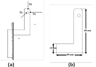
A three force component force dynamometer for cutting force measurement in turning application was designed and developed. The schematic representation of the dynamometer is shown in Figure 1. This tool shank type dynamometer consist of three strain gauges mounted on its outer surfaces capable of measuring feed force, main force and thrust force during turning process. The dynamometer was further connected to computer through data acquisition card and is statically calibrated to measure the resulting voltage from Wheatstone bridge.
Figure 1 Schematic representation of experimental setup
2.2 Data acquisition
Data acquisition system along with computer and programmable software are used to obtain real time
information about the cutting forces during metal cutting. It reads and store all the data concerned with cutting forces automatically from the wheat stone bridge circuit. As the output from the circuit is very low due to high stiffness of flexible mechanical element of dynamometer, data acquisition system not only amplifies but also converts the data into digital signals. Furthermore the DAQ programmable software is also capable of averaging and graphical simulation of the force signal obtained from the circuit during cutting process. All the specification of experimental equipments used are listed in Table 1.
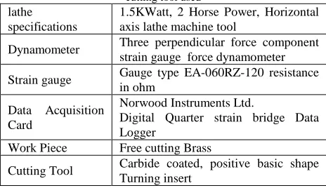
Table 1 Specifications of experimental equipments, work piece and cutting tool used
lathe
specifications
1.5KWatt, 2 Horse Power, Horizontal axis lathe machine tool
Dynamometer Three perpendicular force component strain gauge force dynamometer Strain gauge Gauge type EA-060RZ-120 resistance
in ohm Data Acquisition Card
Norwood Instruments Ltd.
Digital Quarter strain bridge Data Logger
Work Piece Free cutting Brass
Cutting Tool Carbide coated, positive basic shape Turning insert
3.
Design and Construction of dynamometer
for turning process
3.1
Design criterions for dynamometer
www.ijiset.com
3.2
Dynamic properties of dynamometer
The vibration frequency at which the dynamometer is mounted in a machine tool should conform its natural frequency for cutting force measurements. Natural frequency of force dynamometer according to [21] must be at least four time to machine tool operating frequency. The machine tool frequency is related to the spindle speed and is given as.
=
(1) According to [21] the relation for natural frequency of force dynamometer will be>
(2)
shown in Figure 2. The dynamometer is assumed to be a bend cantilever beam subjected to three dimensional loading. To measure the stiffness for each direction of applied load fundamental equations for deflection in bend cantilever are applied.
Figure 2
tool holder force dynamometer under
three dimensional loads
Stiffness in x direction is given as
(3)
Stiffness in y direction is given as
(For member a)
(4)
(For member b)
(5)
Stiffness in z direction is given as
(6)
To measure natural frequency of force dynamometer the following relation is used by assuming dynamometer as s small mass attached to flexible element.
(7)
Where m represents the mass of dynamometer and k is stiffness of dynamometer material used. In this study three values of stiffness are measured for all three perpendicular force components and the least value among them is selected for measurement of natural frequency. Shown below
(8)
The natural frequency in the current study is 503.54 cycle/sec. According to [21] frequency requirement should be fd > 4*n/60
= 4*1000/60=66.66 cycle/sec
which is high enough even if the speed of the spindle is upto 1000rpm.3.3
The orientation of the strain gauges on the
dynamometer
For precision in cutting force values during turning process high accuracy is important in the wheat stone bridge circuit, therefore proper orientation is necessary for the strain gauges to be mounted on the outer surfaces of the force dynamometer. Shown in Figure 3 three strain gauges were mounted on the force dynamometer to measure all the three component of forces x, y and z respectively.
Strain gauge 02 mounted on dynamometer surface is subjected to tensile stress during metal cutting by the main cutting force denoted by Fx and is used to measure that force. Similarly strain gauge 01 is subjected to both compressive and tensile stress depends on spindle rotation direction either clock wise or a counter clock wise by the thrust force denoted by Fy and strain gauge 03 is subjected to tensile stress by feed force denoted by Fz and are used to measure these forces.
3.4
Dynamometer construction
3.4.1.
Mounting of strain gauges and the
dynamometer
After selecting proper orientation for the strain gauges on the dynamometer, next step is to mount theses strain gauges on the dynamometer. Super glue was used to mount them on selected surfaces of the force dynamometer shown in Figure 3 and were coated with clear silicone gel to protect them from hot metal chip come in contact during metal cutting process.
The tool holder type dynamometer was then mounted on tool post of horizontal axis lathe machine to measure the cutting forces as a response from a local deformation produced in tool holder during metal cutting in turning. Shown in Figure 4.
Figure 4: Photograph of the cutting force measurement system
3.5
Dynamometer calibration
3.4.2.
Static calibration of the dynamometer
Calibration of force dynamometer is necessary in order to achieve the accurate results from the wheat stone bridge as a response of change in resistance due to local deformation of force dynamometer during metal cutting process. This calibration was done for all the three perpendicular force components under static condition and the obtained strain was averaged for each direction. Figure 5 shown below shows calibration curves obtained for all the three
components along with cross sensitivity. The resulting effect of loading in one direction in response to the other was also measured but obtained values are small enough to be ignored. For consistency each of the calibration tests was repeated three times and the dynamometer was tested for 10 minutes idle before taking each reading.
www.ijiset.com
3.6
Experimental results
3.6.1.
Cutting force measurements
For measurements of cutting forces a strain gauge based force dynamometer was used (Figure 3). Horizontal axis lathe machine tool was used to perform all the experiments. Specification of all other equipments used in current experimental work is given in Table 1.
3.6.2.
Chemical composition and Properties of Brass
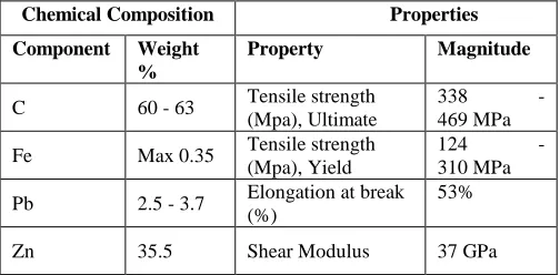
The chemical composition and properties of work piece material (Brass) used for the cutting force measurements are given in the Table 2.
Table 2 Chemical composition and Properties of a Free-Cutting Brass, UNS C36000.
Chemical Composition Properties Component Weight
%
Property Magnitude
C 60 - 63 Tensile strength (Mpa), Ultimate
338 - 469 MPa Fe Max 0.35 Tensile strength
(Mpa), Yield
124 - 310 MPa Pb 2.5 - 3.7 Elongation at break
(%)
53%
Zn 35.5 Shear Modulus 37 GPa
3.7
Experimental setup
Three force components strain gauge based force dynamometer with sensitivity of ±1% was mounted on horizontal axis lathe machine to measure the cutting forces in all three directions i.e. .x ,y and z respectively during turning of free cutting brass metal as shown in Figure 4.
It was further connected to digital quarter Strain Bridge in connection with computer and necessary software to record and analyse the data obtained from the force dynamometer in the form of change in voltage with time. For precision in force and respective voltage relation calibration of force dynamometer is necessary therefore dynamometer was statically calibrated prior to force measurements. All the cutting forces are measured and only the average values of the forces from experiments were selected
3.7.1.
Experimental Procedure
The following Table 3 lists all the parameters that were used in cutting force measurements in turning of brass metal and machining is done for dry case only.
Table 3 Different parameters used for cutting force measurements
S. No Parameters Magnitudes
1. Cutting Speeds
(rpm) 400, 660, 1000 2. Depth of cuts
(mm) 0.25, 0.5, 0.75 3. Feed rates
(in/rev) 0.01, 0.02, 0.029 4. Lubricants Dry cutting
www.ijiset.com
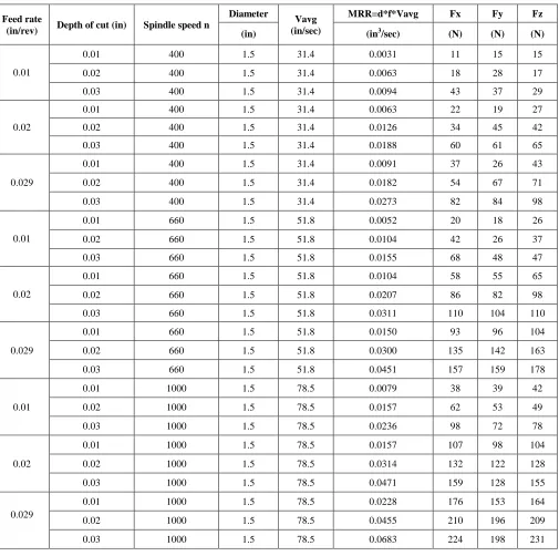
Table 4 MRR at all specified spindle Speeds
Feed rate
(in/rev) Depth of cut (in) Spindle speed n
Diameter
Vavg (in/sec)
MRR=d*f*Vavg Fx Fy Fz
(in) (in3/sec) (N) (N) (N)
0.01
0.01 400 1.5 31.4 0.0031 11 15 15 0.02 400 1.5 31.4 0.0063 18 28 17 0.03 400 1.5 31.4 0.0094 43 37 29
0.02
0.01 400 1.5 31.4 0.0063 22 19 27 0.02 400 1.5 31.4 0.0126 34 45 42 0.03 400 1.5 31.4 0.0188 60 61 65
0.029
0.01 400 1.5 31.4 0.0091 37 26 43 0.02 400 1.5 31.4 0.0182 54 67 71 0.03 400 1.5 31.4 0.0273 82 84 98
0.01
0.01 660 1.5 51.8 0.0052 20 18 26 0.02 660 1.5 51.8 0.0104 42 26 37 0.03 660 1.5 51.8 0.0155 68 48 47
0.02
0.01 660 1.5 51.8 0.0104 58 55 65 0.02 660 1.5 51.8 0.0207 86 82 98 0.03 660 1.5 51.8 0.0311 110 104 110
0.029
0.01 660 1.5 51.8 0.0150 93 96 104 0.02 660 1.5 51.8 0.0300 135 142 163 0.03 660 1.5 51.8 0.0451 157 159 178
0.01
0.01 1000 1.5 78.5 0.0079 38 39 42 0.02 1000 1.5 78.5 0.0157 62 53 49 0.03 1000 1.5 78.5 0.0236 98 72 78
0.02
0.01 1000 1.5 78.5 0.0157 107 98 104 0.02 1000 1.5 78.5 0.0314 132 122 128 0.03 1000 1.5 78.5 0.0471 159 128 155
0.029
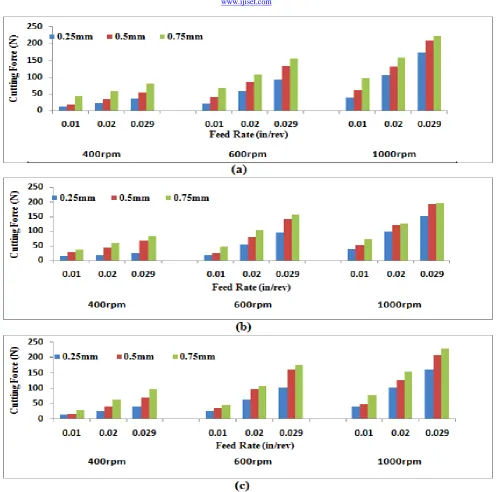
After calculating the material removal rates the values are plotted against the respective cutting forces shown in Figure 7.
Figure 7 Material removal rates Vs cutting forces for feed rates (a) 0.01(b) 0.02 & (c) 0.029rev/in
It was found that the cutting forces increases with increase in MRR. To determine the optimal sets of parameter taguchi method was implemented.
3.8
Taguchi method for optimal process parameters
To optimize the process parameters in manufacturing process many statistical methods were developed and implemented. some of them are discussed by [25] Taguchi method is one of the statistical method developed by [26] to study the entire parameters space with relatively less number of experiments i.e. to overcome full factorial design method problems in which a large number of experiments were required. It consists of the following simple steps.
3.8.1.
Identifying main function and its effects
Main function : Turning of free cutting brass on horizontal axis lathe machine
Side effects : Cutting forces variation in metal cutting
After selecting main function and side effects it is also important to list all factors that affect turning process and categories them into control and noise factors shown in table 5
Table 5 Factors affecting turning process
Control Factors Noise Factors
Depth of cut Material variation Feed rate Machine condition Cutting speed Chattering and vibration
3.8.2.
Identification of noise factors and quality
characteristics
Quality Characteristic Cutting Force measurements Work piece material Free cutting Brass
Cutting tool Coated Carbide Cutting Insert
Operating machine horizontal axis Lathe machine
Testing equipment Force dynamometer
3.8.3.
Identification of objective function to be
optimized
The objective function selected for the current case was nominal-the-best.
3.8.4.
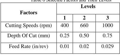
Identification of control factors with levels
The factors and their levels are shown in table 5.3 below.
Table 6 Selected Factors and Their Levels
Factors
Levels
1 2 3
www.ijiset.com
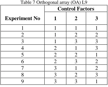
3.8.5.
Orthogonal array selection and matrix
construction
To select an appropriate orthogonal array for conducting the experiments the degree of freedom are to be computed. The same is given below
Table 7 Orthogonal array (OA) L9
Experiment No
Control Factors
1 2 3
1 1 1 1 2 1 2 2 3 1 3 3 4 2 1 3 5 2 2 1 6 2 3 2 7 3 1 2 8 3 2 3 9 3 3 1
3.8.6.
Conduction of the matrix experiment
All the above 9 experiments were conducted according to the orthogonal array mention and the cutting forces were measured using force dynamometer and are listed below in Table 8.
Table 8 Measured values of Cutting forces
Experiments No
Cutting forces
Fx Fy Fz
1 11 15 15 2 34 45 42 3 82 84 98 4 93 96 104 5 42 26 37 6 110 104 110 7 107 98 104 8 210 196 209 9 98 72 78
3.8.7.
Data examination for predicting optimum
control factor levels and its performance
(a)
Result processing
As the objective function In current study is nominal-the-best for all the cutting forces measured during turning of brass metal so the following relation was used to measure the S/N ratio and the values are listed in the Table 9 below.
S/N ratio = (9)
Table 9 Measured tabulated S/N ratios
Experiment No
Control Factors S/N ratio V (rpm) levels t (mm) levels F(in/rev) levels
1 1 1 1 10.54 2 1 2 2 14.54 3 1 3 3 41.38 4 2 1 3 26.32 5 2 2 1 13.57 6 2 3 2 20.84 7 3 1 2 23.07 8 3 2 3 6.20 9 3 3 1 37.45
The factor levels corresponding to the average S/N ratio values are selected to optimize the condition. From the figure 9 above, the average i.e. the optimum values of the factors and their levels obtained are listed in the Table 10.
Table 10 Optimum values of factors and their levels for process optimization
Parameter Levels Optimum values
Speed (rpm) Level 02 660 Depth of cut(mm) Level 03 0.75 Feed rate (in/rev) Level 02 0.02
3.8.8.
Verification of experiments.
The following Table 11 shows confirmation experiments conducted using 660rpm. 0.75mm depth of cut and 0.02 in/rev feed rate.
Table 11 Verification of Experiments
Parameter Optimum Value Fx (N) Fy (N) Fz (N)
Speed (rpm) 660
110 104 110 Depth of cut(mm) 0.75 Feed rate (in/rev) 0.02
4.
Conclusion
using taguchi method for turning process. Based upon the experimental results discussed the following conclusions can be drawn.
• This force dynamometer is capable of measuring three perpendicular components of force simultaneously and the numerical values can be stored in computer through data acquisition card.
• Cutting forces in x, y and z are directly influenced by the change in MRR the percentage increase is low at slow to intermediate but increase when cutting forces changes from intermediates to high speeds
• The use of Taguchi method provides an ease and efficient methodology to obtain optimized process parameters as compared to other statistical methods for process optimization.
Acknowledgments
Manufacturing Process-Labs, Mechanical Engineering department, CECOS University of IT & emerging sciences are highly acknowledged for providing facilities for the experimentation.
References
[1] Fontaine, M., et al., Modelling of cutting forces in ball-end milling with tool–surface inclination: part I: predictive force model and experimental validation. Journal of Materials Processing Technology, 2007. 189(1): p. 73-84.
[2] Sortino, M., G. Totis, and F. Prosperi, Dry turning of sintered molybdenum. Journal of Materials Processing Technology, 2013. 213(7): p. 1179-1190.
[3] Almeida, F., et al., Machining hardmetal with CVD diamond direct coated ceramic tools: effect of tool edge geometry. Diamond and Related Materials, 2005. 14(3): p. 651-656. [4] Cus, F., M. Milfelner, and J. Balic, An intelligent system for
monitoring and optimization of ball-end milling process. Journal of Materials Processing Technology, 2006. 175(1): p. 90-97.
[5] Sun, S., M. Brandt, and M. Dargusch, Characteristics of cutting forces and chip formation in machining of titanium alloys. International Journal of Machine Tools and Manufacture, 2009. 49(7): p. 561-568.
[6] Topal, E.S. and C. Çoğun, A cutting force induced error elimination method for turning operations. Journal of Materials Processing Technology, 2005. 170(1): p. 192-203. [7] Birla, S. Sensors for adaptive control and machine
diagnostics. in Proceedings of the Machine Tool Task Force Conference. 1980.
[8] Cook, N. and E. Loewen, G,; and Shaw, M, C," Machine Tool Dynamometers—A Current Appraisal,". American Machinist, May, 1954. 10.
[9] Korkut, I., A dynamometer design and its construction for milling operation. Materials & design, 2003. 24(8): p. 631-637.
[10]Yaldız, S., et al., Design, development and testing of a four-component milling dynamometer for the measurement of cutting force and torque. Mechanical Systems and Signal Processing, 2007. 21(3): p. 1499-1511.
[11]Yaldız, S. and F. Ünsaçar, A dynamometer design for measurement the cutting forces on turning. Measurement, 2006. 39(1): p. 80-89.
[12]Karabay, S., Analysis of drill dynamometer with octagonal ring type transducers for monitoring of cutting forces in drilling and allied process. Materials & design, 2007. 28(2): p. 673-685.
[13]Oraby, S. and D. Hayhurst, High-capacity compact three-component cutting force dynamometer. International Journal of Machine Tools and Manufacture, 1990. 30(4): p. 549-559. [14]Rizal, M., et al., Development and testing of an integrated
rotating dynamometer on tool holder for milling process. Mechanical Systems and Signal Processing, 2015. 52: p. 559-576.
[15]Jun, M.B., et al., Evaluation of a spindle-based force sensor for monitoring and fault diagnosis of machining operations. International Journal of Machine Tools and Manufacture, 2002. 42(6): p. 741-751.
[16]Kuljanic, E., M. Sortino, and G. Totis, Multisensor approaches for chatter detection in milling. Journal of Sound and Vibration, 2008. 312(4): p. 672-693.
[17]Klocke, F., et al. Experience with the new rotating high speed dynamometer. in Industrial Tooling Conference, Southampton. 2003.
[18]Tlusty, J. and G. Andrews, A critical review of sensors for unmanned machining. CIRP Annals-Manufacturing Technology, 1983. 32(2): p. 563-572.
[19]Karabay, S., Design criteria for electro-mechanical transducers and arrangement for measurement of strains due to metal cutting forces acting on dynamometers. Materials & design, 2007. 28(2): p. 496-506.
[20]Hoffmann, K., The strain gauge, a universal tool of the experimental stress analysis, vd 73004 e. Hottinger Baldwin Messtechnik, Darmstadt, 1973.
[21]Milton, C. and M. Shaw, Metal cutting principles. 1984, Clarendon Press, Oxford Science Publication, UK.
[22]Kim, J.-D. and D.-S. Kim, Development of a combined-type tool dynamometer with a piezo-film accelerometer for an ultra-precision lathe. Journal of Materials Processing Technology, 1997. 71(3): p. 360-366.
[23]TANI, Y., Y. HATAMURA, AND T. NAGAO, Development of small three-component dynamometer for cutting force measurement. Bulletin of JSME, 1983. 26(214): p. 650-658.
[24]Hara, Y., et al., A new micro-cutting device with high stiffness and resolution. CIRP Annals-Manufacturing Technology, 1990. 39(1): p. 375-378.
[25]Athreya, Srinivas, and Y. D. Venkatesh. "Application of taguchi method for optimization of process parameters in improving the surface roughness of lathe facing operation." Int. Refereed J. Eng. Sci 1 (2012): 13-19. [26]Taguchi G, Konishi S ,Taguchi Methods, orthogonal arrays
www.ijiset.com
Muhammad Imran Hanif completed his B.Sc in Mechanical
Engineering from University of Engineering & Technology, Peshawar, Pakistan in 2008. He also received his M.Sc degree in Manufacturing System Engineering from same University in 2015 and currently enrolled in PhD in industrial department UET Peshawar. His current research interest includes design and manufacturing and currently working as Assistant Professor at CECOS University of I.T & Emerging science, Peshawar, Pakistan. He is associated with teaching profession from the last six years apart from one year field experience as Power Engineer at Mobilink pvt ltd Pakistan.
Muhammad Aamir received his B.Sc degree in Mechanical
Engineering in 2006 from the University of Engineering & Technology, Peshawar, Pakistan and M.Sc degree in Design and Manufacturing with distinction from CECOS University of I.T and Emerging Sciences, Peshawar, Pakistan in 2016. His current research interest includes design, manufacturing, advance materials, Alloy design and development of lead free soldering in electronics. He is associated with teaching profession from last seven years and currently working as Academic Coordinator, Mechanical Engineering Department, CECOS University. He was also awarded as best faculty member award for the year 2012 in CECOS University.
Riaz Muhammadgraduated in Mechanical Engineering with distinction from UET Peshawar, Pakistan, in 2006 followed by his Master and PhD degrees in Mechanical Engineering from Ghulam Ishaq Khan Institute of Science and Technology (GIKI) and Loughborough University in 2009 and 2013, respectively. He is currently working as an Associate Professor in the Department of Mechanical Engineering, CECOS University of IT and Emerging Sciences, Pakistan. His research activities include finite element modeling, hybrid machining process, composite, polymers and biomedical materials.