Development of Power Generation Unit Using Low
Boiling Point Liquid Powered By Solar Panel
D. Sai Praveen, M. Tharun
R.M.K. College of Engineering and Technology, Tamilnadu, India
ABSTRACT: A Flat solar plant uses long, trough-shaped solar concentrators to collect solar heat and focus it onto a linear heat absorber. These reflectors track the Sun across the sky for maximum efficiency. Closely related is the Fresnel collection system, which approximates the Flat trough with long, flat mirrors that can also track the Sun. In both systems a heat collection fluid is pumped through the heat receiver. The heat collected is usually used either directly or indirectly to raise steam and drive a steam turbine generator. Flat trough reflectors can achieve a concentration ratio of up to 100. Some Flat trough plants have been built with heat energy storage, which allows them to operate for longer periods each day. In this paper we are going to investigate a operating temperature of working fluid to run a steam turbine . Experimentally investigate solar thermal power plan to run a submerged pump
I. INTRODUCTION
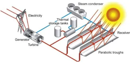
The parabolic trough solar power plant takes its name from the trough-shaped reflector that is used to capture and concentrate the solar heat energy. The collector is much longer than it is wide, and has a parabolic cross section. Each trough is aligned on a north–south axis and provided with a system to allow it to track the Sun across the sky. As it follows the movement of the Sun, the reflector focuses the sunlight onto a solar energy receiver that runs along the length of the trough and is positioned at its focus. These concentrators are sometimes called line focusing solar thermal plants because the sunlight is concentrated along a line.
Closely related to the parabolic trough is the Fresnel reflector, a simplified version of the parabolic trough in which the trough shape is approximated by a series of long, flat—or nearly flat—reflectors that are generally mounted on the ground. The solar energy receiver is mounted separately from the reflectors on a framework that places it above the reflectors. This system is not as efficient at concentrating solar energy as the solar trough, but it is significantly cheaper to construct. The aim of the Fresnel design is to achieve simplicity and low capital cost. However, the technology is less well tested than the more conventional solar trough system.
1.1 Line Focusing Origins
The parabolic trough is the oldest of the modern solar thermal technologies. The first recorded version is that of a Dr. Maier of Aalen and a Mr. Remshalden of Stuttgart, who developed a system based on a parabolic trough collector to generate steam. Their system was followed in 1912–13 by a facility built in Cairo by U.S. inventor Frank Shuman. The plant used tracking solar troughs to generate steam for a steam engine, although the initial plan was for the plant to generate electricity.1 The project comprised five collectors, each 62 m long and 4 m in width. The steam that the collectors were able to produce was equivalent to a generating capacity of 41 kW.
The Fresnel reflector system is based on a similar principle to the Fresnel lens that was originally developed for lighthouses by the French physicist Augustin-Jean Fresnel. The earliest example of a Fresnel reflector for concentrating solar power was developed by an Italian, Giovanni Francia, who patented his work in 1962. A prototype based on his design was built in France in 1964. The technology did not thrive then, but it was picked up again in Australia in the 1990s, where a large-scale demonstration project was built. Since then plants have also been constructed in the United States and in Spain.
1.2 Parabolic Trough Technology
A parabolic trough is a special type of solar concentrator that has a parabolic cross section (it is parabolic in two dimensions) but is linear in the third dimension. The result is that the parabolic shape is extended linearly to make a long reflector. The shape of the reflector causes sunlight to be concentrated along a line at the focus of the parabola, a line that runs along the length of the trough. A heat receiver, normally a specially constructed pipe, is positioned exactly at this focus so that it can absorb the heat from the Sun. A heat transfer fluid is pumped through the pipe and carries the heat away. In most plants this fluid passes through a heat exchanger where it heats water to steam; the steam is used to drive a steam turbine generator. A schematic of a parabolic dish power plant is shown in Fig. 4.1.
A PARABOLIC DISH POWER POINT
II. METHODOLOGY
2.1. FRESNEL LENS
Optimal transmittance condition of prism (OTCP) hows when light goes 88 through a prism, if incident edge, emergent edge and the light path inside of prism can form an 89 isosceles triangle and the light is the base of the isosceles triangle. As the result, the incident angle 90 is equal to the emergent angle, the reflectivities are equivalent in two interface, and the total 91 reflectivity is smallest. Also, reference [15] came up with a proposal that the transmittance of s92 vibration light should be chose to be a design target and the following analysis will depend on it. 93 (When light goes through the transparent media from one to another, the incident light and emergent 94 light are coplanar within the normal plane. The complete vibration of natural light could be separated 95 into p-polarized light and s-polarized light. The amplitude of p-polarized light is parallel to the 96 normal plane and s-polarized light is perpendicular to it). As for cylindrical Fresnel lens, the incident 97 angle is increasing along with the position from the center to the edge. Here use OTCP to constrain 98 the edge-prism of the Fresnel lens. As Fig shows, considering to design a cylindrical Fresnel lens 99 with aperture width w=1300mm and the transmittance in the edge is no less than 80% (Relative 100 refraction index, n=1.59), the maximum incident angle should no more than 40°, according to 101 reference.
The bulk of material between the refracting surfaces has no effect (other than increasing absorption losses) on the optical properties of the lens.
In a Fresnel (point focus) lens the bulk of material has been reduced by the extraction of a set of coaxial annular cylinders of material, (Positive focal length Fresnel lenses are almost universally plano-convex.)
The contour of the curved surface is thus approximated by right circular cylindrical portions, which do not contribute to the lens’ optical properties, intersected by conical portions called ―grooves.ǁ Near the center of the lens, these inclined surfaces or ―groovesǁ are nearly parallel to the plane face; toward the outer edge, the inclined surfaces become extremely steep, especially for lenses of low f–number. The inclined surface of each groove is the corresponding portion of the original aspheric surface.
EXISTING PROPOSED
TIN = 273+40 =313K TIN = 273+40 =313K
TOUT =273+43 =316K TOUT =273+60 =333K
Glass temperature Glass temperature =
= 400 c 500 c
Boiling Temp Of H2O Boiling Temp Of ethanol
=100 0 c = 78.370 c Heat gained= 600c Heat gained
= 80.950c
Quantity of H2o = Quantity of ethanol
300ml = 500ml
2.2. COMPONENTS USED
Fresnel lens
12V electric generator 12V submerged pump storage tank
ethanol
12V power generator
III. DESIGN DETAILS
CALCULATION:
Heat Transfer Fluid: ETHANOL
Inner Area of the Receiver
= ∗ ∗L
= ∗0.04∗ 1.5
= 0.1885 ²
Volume of the receiver
=² / 4
= ∗ 0.0402 ∗ 1.5 / 4 = 1.885 ∗ 10−3 3
= ∗
= 997.99 ∗ 1.885 ∗ 10−3 = 1.8812 g
Velocity of HTF
Accordingly to the way we chose the dimensions of the receiver, we took a mass flow rate
similar to the once used by since this system has many variables that need to be determined ( =0̇.02 kg/s). Thus, we were able to find the inlet velocity and mass flow rate of HTF in the tube receiver. From the equation of mass flow rate dependency on velocity, we retrieved the latter:
̇= ∗ ∗
= ̇ ∗ 57
= 0.02 997.99 ∗ 0.1885
= 1.063 ∗ 10−4 /
According to Stefan-Boltzmann’s Law, the amount of energy emitted by a body is:
̇= ∗ ∗ ∗ 4
̇is radiation heat transfer
T is the temperature of the body’s surface A is the area of the body
σ is the Stefan-Boltzmann constant = 5.669 ∗ 10−8 / ². 4
The material that is used in the tube receiver is copper which will be black anodized in
order to minimize heat losses. The emissivity of black anodized copper is = 0.88
Assuming that the same DNI that the parabola receives is reflected on the receiver:
̇= ̇
= 1235.4 / ²
Then the temperature at the surface of the receiver is: = ( ̇/ ∗ ) 1/4
= (1235.4 / 0.88 ∗ 5.669 ∗ 10−8 ) 1/4
= 396.69 = 123.67 °C
Reynold’s Number
= ( ∗ ∗ ) /
In a fully developed laminar flow, the average velocity is half the maximum velocity in the centerline. From our CFD simulation using ANSYS, we could find the maximum velocity at the centerline of the tube as well as the average velocity:
= 1.251∗ 10−4 m/s
= 2 = 6.255 ∗ 10−5 / The Reynold’s Number Equation becomes:
= 997.99 ∗ 6.255 ∗ 10−5 ∗ 0.04 / 0.0010016 = 2.493
Calculation of hcopper Nusselt Number:
In a laminar flow and for or a circular cross sectional area with a constant surface heat flux, the Nusselt number is:
= ℎ / = 4.36
Given the thermal conductivity of pure copper: k= 386 W/m.K and the inner diameter of the tube
Din= 0.04 m
The convective heat transfer coefficient:
ℎ = ∗/
ℎ = 386 ∗ 4.36 0.04
ℎ = 42 074 / ².K
Hydrodynamic Entry Length Calculation ℎ laminar = 0.05 Re ℎ = 0.05 ∗ 2.493 ∗ 0.04 ℎ = 4.98 ∗ 10−3 K
Pressure Drop Calculation
A drop in the initial pressure occurs due to the viscosity of the HTF; this drop also called Pressure Loss is the main reason of energy loss in the pipe.
∆ = 1 − 2 ∆ = 32 ∗ ∗ ∗ ²
∆ = 32 ∗ 0.0010016 ∗ 1.5 ∗ 6.255 ∗ 10−5 0.04²
∆ = 1.879 ∗ 10−3
The pressure loss in the receiver is very small which means that most of the pressure drop will come from the head loss in the heat exchanger. The heat exchanger pressure drop will be calculated later in the heat exchanger section.
GENERATOR SPECIFICATION:
• SPEED = 100rpm • VOLTAGE = 12V
VOLTAGE BOOSTER SPECIFICATION:
• VOLTAGE = 12V • POWER = 2W
SUBMERSIBLE PUMP SPECIFICATION:
• VOLTAGE = 12V
• POWER CONSUMPTION = 0.4W to 1.5 W
IV. WORKING PRIINCIPLE
The performance of the optimized cylindrical Fresnel lens will be processed by simulation. During the designing phase, the center wavelength of visible light was chosen to calculate the parameters. In order to investigate its performance on the whole visible light, 160 two factors will be taken into account. One is the parallactic angle of the sun δ, which is caused by 161 non-parallelism of sunlight , showing in Fig.4. Another is the refraction index differences 162 among different wavelength lights. Here predefines two edge rays including near-ultraviolet light 163.
Light from the sunlight is allowed to pass on the top surface of the fresnel lens then the working fluid boils. When the ethanol achieves boiling point temperature at suitable pressure, the process gets initiated. After a period of time ethanol achieves the super heated temperature at temperature greater than 85 degrees and at a pressure greater than 4 bar and is allowed to pass through the small orifice. there is a transparent glass which transmit the steam to the Chanel. The pipings are made using PVC which are highly resistant to heat coefficient. 12V pump is allowed to rotate the working fluid to run the generated.
Finally the powered obtained can be stored in batteries and can also be used for commercial purpose. likewise the actual overall thermal efficiency of the plant is increased as usual
V. FUTURE SCOPE
Sun flower solar system is installed with automation sensors. in order to absorb more solar energy, automation is installed. thi increases the efficiency.
solar cell with integrated boilers are installed to increase the super heated temperature of the ethanol.
REFERENCES
[1]. Andreas Fritsch*, Cathy Frantz, Ralf Uhlig ― Techno-economic analysis of solar thermal power plants using liquid sodium as heat transfer
fluid ―
[2]. Mr. F.B.A. Amin, Prof. A.M. Patil, Prof. H.M. Dange, Comparative Study Of Solar Water Heater With And Without Latent Heat Storage System, International Journal of Advanced Engineering Research and Studies, Vol. II/ Issue III/April-June, 2013/89-92.
[4]. Vikram D, Kaushik S, Prashanth V, Nallusamy N, An Improvement in the Solar Water Heating Systems using Phase Change Materials,Proceedings of the International Conference on Renewable Energy for Developing Countries-2006.
[5]. ApurvSamaiyar, Ashish Gupta, ChandMondal, NitinPaliwal, Design And Fabrication Of PCM Based Thermal Energy Storage Device In Solar Water Heater, B.E Project, NIT- JALANDHAR May 2013
[6]. Al-Jumaily, K.E.J., Al-Kaysi, M.K.A., 1998. The study of the performance and efficiency of flat linear Fresnel lens collector with sun tracking system in Iraq. Renew. Energy 14, 41–48. Boyd,
[7]. D.A., Gajewski, R., Swift, R., 1976. A cylindrical blackbody solar energy receiver. Sol. Energy 18, 395–401. [8]. Davis, A., Kuhnlenz, F., 2007. Optical design using Fresnel lenses: basicprinciples and some practical examples.
[9]. Optik & Photonik 2 (4), 52–55. Fernández-García, A., Zarza, E., Valenzuela, L., Pérez, M., 2010. Parabolic-trough solar collectors and their applications. Renew. Sustain. Energy Rev. 14, 1695– 1721. Forristall, R., 2003. Heat Transfer Analysis and Modelling of a Parabolic Trough Solar Receiver Implemented in Engineering Equation Solver. NREL Technical Report.
[10]. Franc, F., Jirka, V., Maly0 , M., Náblek, B., 1986. Concentrating collectors with flat linear Fresnel lenses. Sol. Wind Technol. 3 (2), 77– Holmgren, M., 2006.
[11]Xsteam for Matlab Available online: (Accessed: June 2015). Ijima, O, 2010. Calibration of pyranometer by Collimation tube method. Radiation Section, Atmospheric Environment Division, Global Environment and Marine Department, Japan Meteorological Agency (JMA), IPC-XI,
Davos, Switzerland. IRENA,
2015. Solar Heat for Industrial Processes: Technology Brief Available online: . Accessed June 2016. Ivancic, A., Mugnier, D., Werner Weiss, G.S., 2014. Solar Heating and Cooling Technology Roadmap. Available online . Kumar,
[12]V., Shrivastava, R.L., Untawale, S.P., 2015. Fresnel lens: a promising alternative of reflectors in concentrated solar power. Renew. Sustain. Energy Rev. 44, 376–390. Leutz, R.,Suzuki, A., 2001. Nonimaging