RESONANT LENGTH CALCULATION AND RADIATION PATTERN SYNTHESIS OF
LONGITUDINAL SLOT ANTENNA IN RECTANGULAR WAVEGUIDE
M. Mondal
Kalpana Chwala Space Technology Cell Department of E & ECE
IIT KGP
Kharagpur-2, India
A. Chakrabarty
Department of Electronics Electrical Communication Engineering IIT KGP
Kharagpur-2, India
Abstract—Main intension is to calculate admittance and radiation pattern of longitudinal shunt slot in rectangular waveguide using Method of Moments (MoM) technique. Resonant length calculation of the slot is a critical parameter in the design of waveguide slot array antenna. All computed results are compared with simulated results. CST Microwave studio is used for the simulation and is totally based on FIT techniques. For computation purpose MATLAB 7.0 is used. The numerical data on transmission and reflection coefficient are evaluated. Method of moment solution is used to calculate resonant length versus slot offset for given waveguide dimension and frequency. E and H
field radiation pattern are calculated for different offset in different frequencies.
1. INTRODUCTION
of the slot is obtained and the solution also provides the resonant length of the slot. The analysis of waveguide longitudinal slot has been carried out by number of workers include the work of Oliner [1], Stevenson [2] and Khac [3]. They work for the effect of the offset of the slot from the centerline of the waveguide. A sinusoidal electrical field distribution along the slot length was assumed. Stegen [5] developed the first theory for longitudinal slots which would permit calculation of the susceptance as well as the conductance. The integral equation for the electric field is solved by the Method of Moments, choosing pulse basis function and point matching technique. Sangster and Lyon [4] used an entire basis with sinusoidal function and concluded that two basis functions are sufficient for the power calculations. Stren and Elliot studied moment method solution for the resonant length. With the help of Stevenson paper in which he established the internal green function for a rectangular waveguide and used those function to analyze scattering from a longitudinal slot excited by an incidentT E10 mode. For design of slotted waveguide array the resonant length must be known very accurately. In the present work attention has been paid to evaluate the electrical characteristic in a rectangular waveguide. The relation between vector potential and electric field [6, 11, 12], radiation pattern is calculated. The analysis is carried out using moment method techniques. The application of aperture field methods permits use of entire domain sinusoidal basis function [14] which gives faster convergence than other current based method. The application of Galerkin techniques leads to symmetric moment matrix which reduces the computation time appreciably. Computed resonant length compare very well with measured results.
2. COMPUTATION OF S PARAMETER OF LONGITUDINAL SLOT ANTENNA
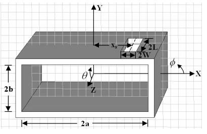
To analyze the structure, the following assumptions are made: • The slot ground plane is of infinite extent.
• There is no variation of electric field along the width of the slot. • Only the transverse component of the magnetic field along the slot
aperture is considered.
• The waveguide is excited by the dominantT E10 mode. The electric field at the slot aperture is expressed as
−−→
E=−u→x M
p=1
Figure 1. Longitudinal slot on the broad wall of a rectangular waveguide.
From the continuity of tangential component of magnetic field at the slot aperture plane, the boundary condition is obtained as follows
Hzinc+Hzint =Hzext
where Hzinc is the z-component incident magnetic field at the slot aperture and for theT E10 mode it can be written as
Hzinc=−jsin
πx
2a
e−jβz
β is the propagation constant ofT E10mode. Hzext is thez-component of the externally scattered magnetic field and by using the plane wave spectrum approach, it is obtained as follows
Hzext = LW
π2kη M p=1 Ep +∞ −∞ +∞ −∞
(k2−k2 z) (k2−k2
z−k2x)1/2
sinc(kxW)
jsinn(kzL). . . p . . . even cos (kzL). . . p . . . odd
pπ 2 1−
2Lkz
pπ 2
×e−jkxxSej{kZz+kXx}dk
xdkz
Galerkin specialization of Method of Moments (MoM) has been used to transform the integral equation into matrix equation. The weighting function is given by
wq(x, y, z)= sin
qπ
2L(z+L)
= 0 elsewhere
Following the procedure of MoM we obtain
[Ep] ={[Lext]−[Lint]}−1[Linc]
where [Ep] is the unknown vector corresponding to the basis coefficients. Waveguide wall thickness has been introduced by treating the slot as stub waveguide.
3. EQUIVALENT CIRCUIT REPRESENTATION
The scattering of a longitudinal slot in the broad wall of a rectangular waveguide is usually modeled by means of equivalent shunt admittance from the measured or computed reflection coefficients Γ. For the fundamental TE(1,0) mode the equivalent normalize slot admittance is obtained as
Y /Y0=−2Γ/(1 + Γ)
The reflection coefficient can be measured quite accurately. It provides a useful basis for comparison with theoretical data. The parameter derived from the reflection coefficient are the normalized admittance and resonant length. The simple shunt model implies that the scattering from the slot is symmetrical, i.e., the back scattering equals the forward scattering. But this is not exactly true for all real slots.
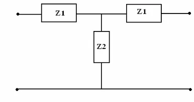
Figure 2. Equivalent circuit of a single longitudinal slot antenna.
Considering an equivalent T-network of the slot, the series (Z1) and shunt (Z2) arm.
Impedances can be determined from the following relations [6], defined by moment method formulations.
Z1=
1 + Γ−T
Z2 =
2T
(1−Γ +T)(1−Γ−T)
MATLAB codes are written to evaluate theS-parameters of the slotted waveguide.
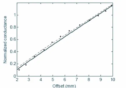
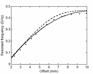
Computation on the basis of the equation of Z1 and Z2 shows that Z1 is negligibly small around resonant frequency of the slot. Therefore, the broad wall longitudinal slot can be represented by shunt admittance. Fig. 3 and Fig. 4 show the variation of resonant conductance with the offset of the slot having length 2L= 16 mm and width 2W = 1 mm. The waveguide is a standard WR90 waveguide (2a = 22.86, 2b = 10.16 and wall thickness t = 1.27 mm). Measured result shows that the resonant conductance increases with the increase of offset value. Computed aperture field on the basis of diagonal matrix and FIT based simulation, shows that the strength of the filed increases with the increase of offset of the slot. As the slot is displaced more and more from the waveguide center line it produces greater interruption to the conduction current and the equivalent magnetic current responsible for radiation into the outer space increases. The variation of resonant frequency of the slot with the change in offset is shown in figures. The figure shows that the resonant frequency of a slot increases with the increase of offset value.
Figure 4. Resonant frequency as a function of slot offset. Solid line: computed, dashed line: simulated, dotted line: measured results. Dimensions are: 2a = 22.86, 2b = 10.16, t = 1.27, 2L = 16, 2w= 1 mm.
4. RADIATION PATTERN
The radiated electric field pattern of the slot can be obtained from [7].
"
E=−∇ ×" F"
where F is the electric vector potential at any point in the space. In spherical coordinate system the electric field
"
E = ur
rsinθ
∂
∂θ (Fθsinθ)− ∂Fθ
∂φ
+uθ
r
1 sinθ
∂Fr
∂θ − ∂ ∂r(rFθ)
+uφ
r ∂
∂r(rFθ)− ∂Fr
∂θ
(b) (a)
Figure 5. (a) E and (b) H-plane radiation patterns of a broad wall longitudinal slot for offset = 3 mm. Solid line: computed, dashed line: simulated with extended ground plane and dotted line: simulated with finite ground plane. Dimensions are: 2a= 22.86, 2b= 10.16,t= 1.27, 2L= 16, 2W = 1 m.
(a) (b)
Figure 6. (a) E and (b) H-plane radiation patterns of a broad wall longitudinal slot for offset = 6 mm. Solid line: computed, dashed line: simulated with extended ground plane and dotted line: simulated with finite ground plane. Dimensions are: 2a= 22.86, 2b= 10.16,t= 1.27, 2L= 16, 2W = 1 mm.
that the slot tends to become a magnetic dipole. Due to lack of some experimental facilities, the measured results are not provided.
is presented. The Taylor distribution for a linear aperture has been considered to design a linear array antenna with specified SLL. The external mutual couplings between the array elements and the finite ground plane effect are considered. For slot coupling case the loaded apertures can be represented by circuit design model. Different procedure specially Fourier series expansion [15] or Fourier transform techniques [16] has been used for slot array calculations.
5. CONCLUSION
In this paper, a single longitudinal slot antenna and it’s computed and simulated results are presented. Resonant frequency, conductance and radiation patterns of an isolated slot are computed assuming the slot ground plane as of infinite extent. It is seen that the strength of the slot aperture electric field and hence the radiation conductance of the longitudinal slot increases with the increase of displacement from the waveguide center line. The simulated radiation patterns of an isolated longitudinal slot shows that the diffraction effects from the edges of finite size ground plane only affects theE-plane radiation patterns of the slot. For liner array antenna, required Taylor array synthesis for getting desired side lobe level (SLL).
REFERENCES
1. Oliner, A. A., “The impedance properties of narrow radiating slots in the broad face of rectangular waveguide, Part I — Theory,”IRE
Trans. Antennas Propagat., Vol. 5, 4–20, Jan. 1957.
2. Stevenson, A. F., “Theory of slots in rectangular waveguides,” J.
Appl. Phys., Vol. 19, 24–38, Jan. 1948.
3. Khac, T. B., “A study of some slot discontinuities in rectangular waveguides,” Ph.D. dissertation, Monash University, Australia, Nov. 1974.
4. Lyon, R. W. and A. J. Sangster, “Efficient moment method analysis of radiating slots in a thick walled rectangular waveguide,” Proc. Inst. Elec. Eng., Vol. 128, Pt. H, No. 4, 197– 205, Aug. 1981.
5. Stegen, R. J., “Longitudinal shunt slot characteristics,” Hughes
Tech. Memo., 261, Nov. 1971.
7. Harrington, R. F., Field Computation by Moment Methods, MacMillan, New York, 1968.
8. Elliott, R. S., Antenna Theory and Design, Prentice-Hall, Englewood Cliffs, NJ, 1981.
9. Stern, G. J. and R. S. Elliot, “Resonant length of longitudinal slots and validity of circuit representation: Theory and experiment,”
IEEE Trans. Antennas Propagat., Vol. 33, 1264–1271, Nov. 1985.
10. Young, J. C., J. Hirokawa, and M. Ando, “Analysis of a rectangular waveguide, edge slot array with finite wall thickness,”
IEEE Trans. Antennas Propag., Vol. 55, No. 3, 812–818, Mar.
2007.
11. Das, S. and A. Chakrabarty, “A novel modeling technique to solve a class of rectangular waveguide based circuit and radiator,”
Progress In Electromagnetic Research, PIER 61, 231–252, 2006.
12. Tiwari, A. K., D. R. Poddar, and B. N. Das, “On the equivalent radius of a radiating slot in impedance calculation,” Progress In
Electromagnetic Research, PIER 74, 47–56, 2007.
13. Khalaj-Amirhosseini, M., “Analysis of longitudinally inhomoge-neous waveguides using the method of moments,” Progress In
Electromagnetics Research, PIER 74, 57–67, 2007.
14. Das, S., A. Chakrabarty, and A. Chakraborty, “Characteristics of an offset longitudinal/transverse slot coupled crossed waveguide junction using multiple cavity modeling technique considering the TE00 mode at the slot aperture,” Progress In Electromagnetics
Research, PIER 67, 297–316, 2007.
15. Park, J. K., J. N. Lee, D. H. Shin, and H. J. Eom, “A full-wave analysis of a coaxial waveguide slot bridge using the Fourier transform technique,” J. of Electromagn. Waves and
Appl., Vol. 20, No. 2, 143–158, 2006.
16. Khalaj-Amirhosseini, M., “Analysis of longitudinally inhomoge-neous waveguides using the Fourier series expansion,”J. of