A Multifunction Automatic Smart Controller
for Solar and Grid System for Household
Utility
Sayali S Kulat
1, N. R. Kulkarni
2PG Student, Department of Electrical Engineering, PES‘S Modern College of Engineering, Pune, India1
Vice Principal, Professor & Head, Department of Electrical Engineering, PES‘S Modern College of Engineering, Pune,
India.2
ABSTRACT:
S
olar energy is a non-depleting, site dependent, non-polluting, and potential source of energy. However it is of unpredictable nature. It is of prime importance to develop a supervisory system which controls and monitors the energy production and also evaluates the consumption. This is necessary so as to maintain a balance between the production and consumption needs.The Photovoltaic (PV) power systems convert sunlight directly into electricity. PV power system installed at a residence can generate electricity which can meet most or his total electricity requirement .Excess power generated during daytime can be used for future need i.e. at night time. Thus the house remains connected to the electrical utility all the times.
The proposed system is called a ‗Multifunction Automatic Smart Controller for Solar and Grid System for Household Utility‘. This consists of a smart controller based design for cost effective operation of solar-grid tied system. The proposed method is cheap, efficient, reliable and cost effective. The system has been tested for the 20 Wattsolar panel with the battery backup storage and its effectiveness is observed. Hardware implementation of Incremental Conductance MPPT using Buck Converter is designed and explained.
KEYWORDS: Incremental Conductance, MPPT, Photovoltaic Module ,SEPI.
I. INTRODUCTION
efficiency of PV systems, some methods are proposed, among which is a new concept called ―Maximum Power Point Tracking‖ (MPPT). All MPPT methods follow the same goal which is maximizing the PV array output power by tracking the maximum power on every operating condition. A switch-mode DC-DC converter is heart of MPPT hardware. A DC-DC converter therefore implemented to produce a constant voltage and deliver maximum power from solar panel to load. The output voltages of dc-dc converters are generally controlled by using a switching concept. IGBT‘s or MOSFET‘S are used for this purpose. For output voltage regulation Pulse width modulation (PWM) is widely used.
II.SYSTEM MODULES
2.1 Maximum Power Point Tracking (MPPT) Methods
The Maximum Power Point Tracking (MPPT) Methods are usually implemented PV modules so as to increase the efficiency of PV modules. The MPPT methods are:
(i) Perturb and Observe Method (ii) Constant Voltage Method
(iii) Incremental Conductance Method
2.1.1 Perturb and Observe Method
Figure 1The Perturb and Observe Method for MPPT
This method of power point tracking follows the procedure of constantly checking the voltage (or current in some systems) and continuing to increase the voltage as long as the power continues to increase. After passing over the maximum power point the power will begin to decrease which the algorithm will interpret as having gone too far and will start decreasing the voltage to compensate. This process continues to iterate until the maximum power point has been reached. Figure 1 provides a graphical representation of this algorithm in operation. One of the disadvantages of the perturb and observe method is that based on the algorithm, the system will continue to oscillate around the maximum power point. This can lead to inefficiencies, especially in situations when the irradiance is low and
2.1.2 Constant Voltage Method
Figure 2 Constant Voltage Method for MPPT
The system will temporarily set the PV current to zero in order to determine the open circuit voltage. Once it has this value it can calculate, based on the specified ratio, what the operating voltage should be and the system can begin moving to that point. There is a specific amount of time, which can be programmed into the system, to wait before isolating the source and repeating the calculation. This method is inherently much less efficient than either the perturb and observe method or the incremental conductance algorithm. The primary advantage of this technique is that it requires much less computational time and is a much simpler algorithm than the previous methods.
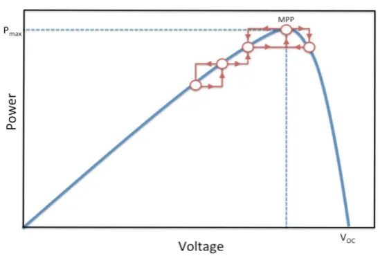
2.1.3 Incremental Conductance Method
Figure3 Basic idea of the Incremental Conductance method on a P–V curve of a solar module
where I and V are the PV array output current and voltage, respectively. The left-hand side of the equations represents the Incremental Conductance of the PV module, and the right-hand side represents the instantaneous conductance. It is obvious that when the ratio of change in the output conductance is equal to the negative output conductance, the solar array will operate at the MPP. In other words, by comparing the conductance at each sampling time, the MPPT will track the maximum power of the PV module. The accuracy of this method is proven in where it mentions that the Incremental Conductance method can track the true MPPs independent of PV array characteristics.
.
2.1.4. Incremental Conductance with Direct Control Method
Conventional MPPT systems have two independent control loops to control the MPPT. The first control loop contains the MPPT algorithm, and the second one is usually a proportional (P) or P–integral (PI) controller. A less obvious, but effective way of performing the Incremental Conductance technique is to use the instantaneous conductance and the incremental conductance to generate an error signal.
And this e goes to zero at MPP; however, it is not zero at most of the operating points. However, the MPPT system of standalone PV is a nonlinear control problem due to the nonlinearity nature of PV and unpredictable environmental conditions, and hence, PI controllers do not generally work well.
In this work, the Incremental Conductance method with direct control is selected. The PI control loop is eliminated, and the duty cycle is adjusted directly in the algorithm. The control loop is simplified, and the computational time for tuning controller gains is eliminated. The feasibility of the proposed system is investigated with a dc–dc converter configured as the MPPT. It was mentioned that the power extracted from PV modules with analog circuitry can only operate at the MPP in a predefined illumination level. Therefore, control action is done using a PIC16F877A which performs various control actions. It generates pulse width modulation (PWM) waveform to control the duty cycle of the converter switch according to the Incremental Conductance algorithm.
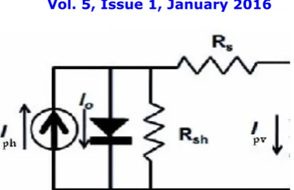
2.2 Photovoltaic (PV) Module
Figure 4 PV cell modelled as diode circuit
The current source Iph represents the cell photocurrent. Rsh and Rs are the intrinsic shunt and series resistances of the cell, respectively. Usually the value of Rsh is very large and that of Rs is very small, hence they may be neglected to simplify the analysis. PV cells are grouped in larger units called PV modules which are further interconnected in a parallel-series configuration to form PV arrays. The photovoltaic panel can be modelled mathematically as given in equations (1) - (4). [1, 8]
Module photo-current:
---(1)
Module reverse saturation current
---(2)
The module saturation current Irs varies with the cell temperature, which is given by
---(3)
The output current of PV module is
---(4)
Where
Vpv is output voltage of a PV module (V) Ipv is output current of a PV module (A) Tr is the reference temperature = 298 K
T is the module operating temperature in Kelvin Iph is the light generated current in a PV module (A) Irs is the cell reverse saturation current (A)
A = B is an ideality factor = 1.6
K is Boltzmann constant = 1.3805 × 10⁻²³ J/K q is Electron charge = 1.6 × 10⁻¹⁹ C
Ego is the band gap for silicon = 1.1 eV K0 is constant
Ns is the number of cells connected in series Np is the number of cells connected in parallel
2.3 SEPI Converter
The single-ended primary-inductor converter (SEPIC) is a type of DC/DC converter allowing the electrical potential (voltage) at its output to be greater than, less than, or equal to that at its input. The output of the SEPIC is controlled by the duty cycle of the control transistor.
Figure 5 The schematic diagram for a basic SEPIC
A SEPIC is essentially a boost converter followed by a buck-boost converter, therefore it is similar to a traditional buck-boost converter, but has advantages of having non-inverted output (the output has the same voltage polarity as the input), using a series capacitor to couple energy from the input to the output (and thus can respond more gracefully to a short-circuit output), and being capable of true shutdown: when the switch is turned off, its output drops to 0 V, following a fairly hefty transient dump of charge.
The schematic diagram for a basic SEPIC is shown in Figure 6. As with other switched mode power supplies (specifically DC-to-DC converters), the SEPIC exchanges energy between the capacitors and inductors in
order to convert from one voltage to another. The amount of energy exchanged is controlled by switch S1, which is typically a transistor such as a MOSFET. MOSFETs offer much higher input impedance and lower voltage drop than bipolar junction transistors (BJTs), and do not require biasing resistors as MOSFET switching is controlled by differences in voltage rather than a current, as with BJTs).
1) Continuous mode
A SEPIC is said to be in continuous-conduction mode ("continuous mode") if the current through the inductor L1 never falls to zero. During a SEPIC's steady-state operation, the average voltage across capacitor C1 (VC1) is equal to the
input voltage (Vin). Because capacitor C1 blocks direct current (DC), the average current through it (IC1) is zero,
making inductor L2 the only source of DC load current. Therefore, the average current through inductor L2 (IL2) is the
same as the average load current and hence independent of the input voltage. Looking at average voltages, the following can be written:
---(5)
Because the average voltage of VC1 is equal to VIN, VL1 = −VL2. For this reason, the two inductors can be wound on the
same core. Since the voltages are the same in magnitude, their effects of the mutual inductance will be zero, assuming the polarity of the windings is correct. Also, since the voltages are the same in magnitude, the ripple currents from the two inductors will be equal in magnitude.
The average currents can be summed as follows (average capacitor currents must be zero): ---(6)
2) Discontinuous mode
A SEPIC is said to be in discontinuous-conduction mode or discontinuous mode if the current through the inductor L1 is allowed to fall to zero.
The resistances in the inductors and the capacitors can also have large effects on the converter efficiency and ripple. Inductors with lower series resistance allow less energy to be dissipated as heat, resulting in greater efficiency (a larger portion of the input power being transferred to the load). Capacitors with low equivalent series resistance (ESR) should also be used for C1 and C2 to minimize ripple and prevent heat build-up, especially in C1 where the current is changing direction frequently.
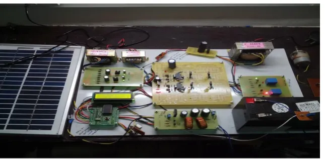
III. SYSTEM ANALYSIS & DESCRIPTION
Figure 6 Block Diagram of the system
To track the Maximum power point, a Hardware section is required which consist of different parts. The figure 7 above shows the block diagram of the system. It consist of Solar Panel ,SEPIC Convertor, Invertor , Microcontroller, Opto Coupler , Liquid Crystal Display , current and voltage measurement unit and driver circuits. The solar panel will harness the solar power which is stored in the battery. The microcontroller switches the supply between the mains and the battery through the relays. The SEPIC convertor maintains the battery voltage and also charges the batter. The microcontroller also provides the PWM pulses at the gate of the MOSFET
The solar panel supplies voltage to the buck boost (sepic convertor) .The buck boost convertor ensures that the voltage is maintained at 12 v .The buck boost convertor supplies the voltage to the battery .Initially the solar panel output is given to the battery. The output of the solar panel is DC hence this DC output will charge the battery as the battery can accept only DC input and provides DC output. The solar panel used in the circuit is of 12V and also the battery used is of 12V.Now this DC output from the battery is given to the inverter circuit which converts the DC signal to AC. The converted AC output is given to the relay which acts as an automatic switch. The output load is connected to the relay, so whenever the relay gets a ON signal from the microcontroller unit , it will turn ON the output load and whenever the input to the relay is OFF, it will turn OFF the output load.
When the battery level goes below a specific value then mains will drive the relay and the relay will then drive the load. Simultaneously the AC supply is converted to DC .The DC voltage will drive the opto coupler which will then trigger the SEPIC convertor and the battery gets charged.
The microcontroller is the heart of the circuit that would provide switching between the AC mains and the battery. Actually both the relays connected in the circuit do not receive the signal directly via the battery and the AC mains instead they are connected to the microcontroller through which they turned ON and OFF the load.
The microcontroller decides the switching:
1. It first checks whether both the battery and the AC mains are available are not. If both are available then it considers the AC mains thereby keeping the battery output for backup. In this period of time the microcontroller checks the battery voltage, if the battery voltage is low then the solar panel charges the battery to the maximum.
2. If the AC mains is not available then it considers the battery voltage which is fully charged.
3. To display the values of input voltage and current and output voltage and current we have connected a LCD to the microcontroller.
V. RESULT AND DISCUSSION
Though numerous rechargeable batteries exist, the most commonly used battery in solar systems is the lead-acid battery. This is mainly because of the price to power ratio is superior to all other types and due to the fact that this is a proven technology. The lead acid battery of 12V is charged using MPPT technique. Table 1 below shows the observations of variation of voltage, current of battery and solar panel with respect to time which has been taken in the third week of December 2015 from 9:00 am to 6:00 pm.
Time
Input voltage
( Volts)
Input
Current
(Ampere)
Power
( Watts)
9 a.m.
13
0.02
0.26
10 a.m.
14.2
0.022
0.31
11 a.m.
15
0.024
0.36
12 noon
15.5
0.028
0.43
01 p.m.
16
0.029
0.46
02 p.m.
17
0.030
0.51
03 p.m.
17.5
0.031
0.54
04 p.m.
15
0.024
0.36
05 p.m.
12
0.015
0.18
06 p.m.
06
0.001
0.006
VI. CONCLUSION
Thus we have been able to design a multifunction automatic smart controller for solar and grid System to be used as household utility where MPPT was tracked effectively by using a SEPIC Converter. Controller algorithm for a smart controller based solar-grid hybrid system has been presented, specifically for effective utilization of power from the Solar PV. All techniques rely on the ability of effective co-operation of different units in the hybrid system and mainly the programming algorithm and interface used with smart controller. The described algorithm is demonstrated with practical observation from the lab. This method can be used as a cheap alternative to save energy even in a Grid tied system and it is expected that the consumer will be encouraged to use this form of energy in place of the grid. Effective use of such an alternative will ease out the burden on the existing grids and will also play a positive role in terms of its effect on the climatic conditions.
Future work may involve developing different Microcontroller based dedicated MPPT controller for solar PV module based on the different algorithm such as observe & perturbation, computational method etc. Future work may involve making the system remote controlled with usage of battery banks to improve the reliability of the system.
REFERENCES
[1] Azadeh Safari, Saad Mekhilef, Simulation and Hardware Implementation of Incremental Conductance MPPT With Direct Control Method Using Cuk Converter, IEEE Transactions on Industrial Electronics, April 2011
[2] Srushti R.Chafle, Uttam B. Vaidya, Z.J.Khan, Design of Cuk Converter With MPPT Technique, International Journal Of Innovative Research In Electrical, Electronics, Instrumentation And Control Engineering, July 2013
[3] Neeraj Tiwari,D. Bhagwan Das, MPPT Controller For Photo Voltaic Systems Using Cuk DC/DC Converter, International Journal of Advanced Technology & Engineering Research, May 2012
[4] Pradeep Kumar Yadav, Comparison of MPPT Algorithms for DC-DC Converters Based PV Systems, International Journal of Advanced Research in Electrical, Electronics and Instrumentation Engineering, July 2012
[5] Trishan Esram, Patrick L. Chapman, Comparison of Photovoltaic Array Maximum Power Point Tracking Techniques, The authors are with Grainger Center for Electric Machinery and Electromechanics at the University of Illinois at Urbana- Champaign. This project was sponsored by the National Science Foundation ECS-01-
34208.
[6] M. Manikanda Prabhu, Dr. A. Mannvannan Modeling And Performance Analysis Of PV Panel Using Incremental Conductance Maximum Power Point Tracking, International Journal of Engineering Research & Technology (IJERT), March 2013
[7] Harsha P.P, Dhanya P.M, Karthika K, Simulation and Proposed Hardware Implementation of MPP Controller for a solar PV System, International Journal of Advanced Electrical and Electronics Engineering, (IJAEEE)
[8] N. Pandiarajan, Ranganath Muthu, Mathematical Modeling of Photovoltaic Module with Simulink, International Conference on Electrical Energy Systems (ICEES 2011), 3-5 Jan 2011
[9] Bidyadhar Subudhi, Raseswari Pradhan, A Comparative Study on Maximum Power Point Tracking Techniques for Photovoltaic Power Systems, IEEE transactions on Sustainable Energy, January 2013
[10] Chih-Yu Yang, Chun-Yu Hsieh, Fu-Kuei Feng, Ke-Horng Chen, Highly Efficient Analog Maximum Power Point Tracking (AMPPT) in a Photovoltaic System, IEEE transactions On Circuits And Systems—I: regular papers, July 2012