Available online:
https://edupediapublications.org/journals/index.php/IJR/
P a g e | 2198An Improvement of Network’s Lifetime Based on p
LEACH
Algorithm for WSN
Mohd Fahad Perwez
Department of Electronics and Communication Engineering World Institute of Technology,
MDU Rohtak Gurugram, India
[email protected]
Abstract:
Applications of Wireless Sensor Network (WSN) have augmented in fields such as area monitoring, air pollution monitoring, environmental sensing etc. Due to power constraints of sensor in the network, sensor is not usually rechargeable or replaceable. Our key focus lies on improvement of network lifetime so that the battery needs not to be replaced soon. For achieving this aim, there is number of algorithm have been proposed to enhance the network’s lifetime and stability period of the WSN. LEACH (Low Energy Adaptive Clustering Hierarchy) is widely accepted cluster-based hierarchical routing protocol in Wireless Sensor Networks. The proposed protocol pLEACH (partition based LEACH) have added facility that it improve the lifetime of the network as compare to traditional LEACH algorithm. pLEACH algorithm firstly divided the network into optimal number of sectors, and then selects the node which have the highest residual energy as the cluster head of each sector with the help of centralized control of BS(Base Station). The simulation results and analysis shows that pLEACH could outperforms the conventional LEACH in terms of the network lifetime, stability period of the network and residual energy of network.
Keywords: LEACH, pLEACH, WSNs, Base Station
1. Introduction
With the recent advancement of sensor technology, wireless sensor networks (WSNs) have been widely used for both civil and military applications. Due to its large application in military reconnaissance, logistics management, environmental monitoring, agriculture and other commercial areas, WSN has become the efficient technology in the field of communication and computer research area. As Sensor nodes depends on battery power supply and Limited energy storage capacity, therefore utilize the energy of nodes proficiently and extend the networks lifetime, has
become a key design objective for wireless sensor network.
In WSNs, we have to save and balance the energy consumption to a great extent. In order to handle such challenges, Heinzelman et al proposed a clustering algorithm called LEACH [1] and LEACH-C [2]. In both methods, energy consumption can be reduced and the lifetime of network is extended. LEACH comprises of two phases: cluster setup phase and steady state phase (data transmission phase). Cluster heads are elected first then the clusters are formed in set-up phase. In steady phase, the cluster head aggregates the data from the other non-cluster head nodes [4].An algorithm pLEACH is purposed in which the whole network area is partitioned into subareas. In each subarea a cluster head is elected to receive data from other cluster member within the subarea and then forward it to the sink node.
The organization of the paper is as follows: Section II discusses previous clustering algorithms, the LEACH protocols. Section III explains the proposed model, partition-based LEACH (pLEACH). Section IV shows the various simulation analysis and comparisons of proposed work. Section V discusses the conclusion and finally the references.
2. Related Work
A. LEACH
Available online:
https://edupediapublications.org/journals/index.php/IJR/
P a g e | 2199adaptive clustering protocol that uses randomization to distribute the energy load evenly among the sensors in the network. This is an energy-conserving routing protocol for wireless sensor network which was proposed by Heinzelman, Chandrakasan and Balakrishnan [1]. In LEACH, sensor nodes form clusters and the cluster heads acts as routers to the base station. This would save energy since the transmissions will only be done by Cluster Heads (CHs) rather than member nodes of cluster. Optimal number of CHs is assumed to be 5% of the total number of nodes [1]. The operation of LEACH made up of several rounds where each round is divided into two phases: the set-up phase and the steady state phase as shown in Figure 2.1
.
Fig.2.1. Time line showing LEACH operation
During the set-up phase, CH selection and cluster formation are performed. In CH selection, each node participates in a CH election process by generating a random value between 0 and 1. If random number of a sensor node is less than a threshold value T(n) then that node becomes CH. The value of T(n) is calculated using Equation 2.1.
T(n)=
{
𝑃
1−𝑃∗(𝑟 𝑚𝑜𝑑𝑃1)
∶ if n ℰ G
0 ∶ 𝑜𝑡ℎ𝑒𝑟𝑤𝑖𝑠𝑒
(2.1)
Where ‘P’ denotes the desired percentage of sensor nodes to become CHs among all sensor nodes, ‘r’ denotes the current round and ‘G’ is the set of sensor nodes that have not participated in CH selection in previous 1/P rounds.
During steady-state phase data are transferred from the nodes to the cluster head and on to the Base station.
B. LEACH-C
LEACH-C [2] is proposed by Heinzelman et al. The conventional LEACH protocol does not guarantee the best possible number of CHs and their current locations [4, 5]. All nodes are required to send their ID, location,
and energy information to the base station during the setup phase of LEACH-C [2]. The base
station is
responsible for assigning the role of
CH to any member node by using its central control algorithm. The centralized control algorithm first specifies the average energy level and then compares that energy level to the energy level of the received signal energy [4]. The base station picks the optimal number of CHs from the nodes with an energy level greater than the average energy level. A list of IDs of these selected nodes is transmitted by the base station to all nodes. From this list, a node having minimum distance from its member nodes is elected as CH of that cluster. The approach used in LEACH-C reduces the energy consumption of CH and member nodes. LEACH-C, a protocol that uses a centralized clustering algorithm and the same steady-state protocol as LEACH.C. Disadvantages of LEACH & LEACH-C
Protocol
In LEACH, the cluster heads are elected in randomization fashion among nodes of specific area. The nodes which have low residual energy have the same priority to those which have high residual energy to be a cluster head this leads to node die first that have low residual energy. Whereas, LEACH-C has improved form of LEACH in which always high residual energy is taken into account uses annealing algorithm to become a cluster head and also to form a better cluster. Besides this, LEACH algorithm at the initialization of every round, each node has to report regarding its residual energy which leads to more energy consumption.
3. Proposed Model
Suppose there are N sensor nodes which are randomly distributed in a circular area with the radius R and collect data in periodical manner. The sink node is located at the center of the area with the coordinate (0, 0). According to the fundamental design of our work, this proposed WSN has the following features:
Available online:
https://edupediapublications.org/journals/index.php/IJR/
P a g e | 2200(b) All nodes can perform data aggregation i.e. fusion.
(c) The transmitting node can adjust the transmit power with the purpose to save energy depending on the distance to the receiver.
In this paper, we use the same network constraint which are specified in [5], Without considering the energy consumption for data fusion, the energy consumption of a cluster head (ECH) node and non
cluster node head i.e member node (ENCH) can be
calculated as (1) and (2) respectively:
ECH = lEelec(
𝑁
𝐾− 1) + lEelec+lєamp𝑑𝑡𝑜𝑆
𝑛 (1)
ENCH = lEelec + lєamp𝑑𝑡𝑜𝐶𝐻𝑛 (2)
Here dtoSis the distance between cluster head and sink
node, dtoCH is the distance between the member node
and cluster head, єamp is Energy consumption of transceiver of amplification circuit, ‘d’ is Transmission distance and ‘l’is The length of packet.
3.1 Partition-based LEACH
Similar to LEACH-C, the centralized cluster head election scheme [6] is used in the proposed algorithm, partition-based LEACH (pLEACH) is based on the centralized cluster head election scheme. The pLEACH algorithm consists of two phases:
(a) The sink node calculates the best possible number [7] of cluster heads for a given network and accordingly partitions the whole network into sectors.
(b) The base station node selects a node with the highest residual energy in each sector as the cluster head. Finally, the base station node broadcasts the elected heads i.e cluster head in each sectors, and all member nodes join its closest cluster head after receiving the broadcast message.
3.2 Partition.
Assuming the ratio of the optimal number of cluster heads to the total number of nodes is ‘P’ (usually, 5%-6% of the total of nodes). If the total number of nodes
is ‘n’, then the total number of cluster heads is n*p in
the specified network.
Partition algorithm:
(a) Each of the node sends its location and residual energy information to the base station node during the initialization step of network [8]
.
(b) The base station node will participates the network area into several subareas according to the optimal number of expected cluster-head (n*p).
(c) The entire network is divided into n*p sectors starting from the X axis. The central angle ‘θ’ between the two lines forming a sector is 2π / (n* p), as shown in Fig.3.1.
(d) The base station node calculates the central angle ‘ω’ of each node in the network according to the location information submitted by each node. Based on central angle of each node ‘ω’, every node is assigned with the sequence number of its sector.
Fig.3.1 Network partition
‘ω’ calculation: Consider that base station node as the origin of polar coordinates, the ‘ω’ of each node can be computed as:
ψ
=tan−1 ⌊𝑋⌋⌊𝑌⌋ , X= Xnode –Xsink, Y=Ynode –Ysink
Switch (node-coordinate)
Available online:
https://edupediapublications.org/journals/index.php/IJR/
P a g e | 2201Case 1: A node in the first quadrant
ω = tan−1 ⌊𝑋⌋ ⌊𝑌⌋
Case 2: A node in the second quadrant
ω = π - tan−1 ⌊𝑋⌋ ⌊𝑌⌋
Case 3: A node in the third quadrant
ω = π + tan−1 ⌊𝑋⌋ ⌊𝑌⌋
Case 4: A node in the fourth quadrant
ω = 2π - tan−1 ⌊𝑋⌋⌊𝑌⌋
}
(e) A list of partition will be organized according to the ‘ω’ of each node. As shown in Fig.3.2.
Fig.3.2 List of partition
The algorithm for developing list of partition is as follows:
For a node in the network
{
If (it is in partition1) // accord ing to the angle
{Put node ID in partition 1 ;}
Else if (it is in partition 2)
{Put node ID in partition 2 ;}
……
Else
{Put node ID in partition K ;}
}
The algorithm partition’s complexity is just O(K*n), where, 0.03*N ≤ K≤ 0.05*N . This low complexity makes it feasible for practical application.
Fig.3.3. Partition rotation
(f) The data transmission amount in each segment may be unequal, resulting in unequal energy consumption for each section. In order to balance the energy distribution, we can rotate the circle a given angle φ (φ <θ ) before each round, as shown in Fig.3.3, which balances the overall energy distribution in each partition. Since, the list of partition has to be changed in each round.
Cluster Head Selection. After partitioning, the next step is the cluster head selection. The algorithm for the cluster head election is:
(a) At the initialization, each node sends a report message regarding its initial energy and location to the base station node. Based on this, the base station node forms matrices of the distance and the residual energy, and then broadcasts the distance matrix.
Distance Matrix:
where,
dijis the distance from node i to j.
Energy Matrix: (E1,..,Ei,…,En), Eiis the initial energy
Available online:
https://edupediapublications.org/journals/index.php/IJR/
P a g e | 2202(b) The cluster heads are chosen by the base station node. Based on the energy matrix (E1,..,Ei,…,En) the
base station selects the node with the highest energy in each sector as a cluster head. If more than one node has the same energy in a sector, the node with the smallest_ID becomes the cluster head. Since one cluster head is elected in each sector only.
(c) After the determination of cluster head, the base station node broadcasts a message to all nodes. By receiving this message, all the nodes identify the concerned cluster heads in the network and joins by using the distance matrix.
(d) For the appointment of cluster heads, the base station node has to know the residual energy of each node. For reporting the residual energy in each round, we recommend adding the current residual energy value in the data packet, as shown in Fig.3.4. Like this, we do not require to report the residual energy separately. It can save energy consumption to the great extent.
Fig.3.4 The format of data packet
(e) After the steady transmission phase, communication is completed. The base station node has to update energy matrix according to the residual energy value in each data packet.
4. Simulation Analysis and Comparison.
In order to evaluate and improve the performance of pLEACH, we have simulated and analyzed the LEACH protocol and pLEACH protocol in terms of network’s lifetime and energy consumption and made a comparison.
4.1. Simulation Parameters
we implemented the simulation using the model mentioned in Section 3.1, uniformly deploying 100 nodes with the same initial energy in a circular area with the radius of 75m. The length of control message and the data packet is 200 bits and 4000 bits respectively. The simulation observes 5002 rounds of
cluster head appointment. Key network parameters for the simulation are as following.
Eelec=50nJ/bit, ℰamp =10pJ/bit/m2. Note: The initial energy of node is 1Joule.
The simulation is done using MATLAB R2013a (64-Bit) version. The nodes are randomly positioned within circular area. The base station is located at coordinate (0, 0) of the deployment area. The total no of nodes for this simulation is 100 (i.e. n=100).
4.2. Simulation results and comparison
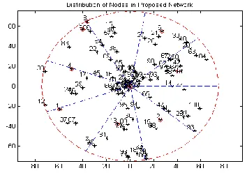
Fig.4.1 shows a WSN with some sensor nodes and a base station. All sensor nodes are shown with star mark and base station with star mark encircled with red color at the centre of the circle with coordinate (0,0). Proposed method works in rounds. Total number of rounds for experiments is 5002. At the start of simulation every node has energy of 1J. Star encircled with red color circle sensor nodes are denoting cluster heads.
Fig 4.1 Distribution of nodes in a proposed model using MATLAB
Available online:
https://edupediapublications.org/journals/index.php/IJR/
P a g e | 2203Fig.4.2.Comparison of number of alive nodes per round between pLEACH and LEACH protocol.
Fig.4.3. shows the comparison of residual energy after each Iteration of LEACH and pLEACH. The residual energy of LEACH after 3368 rounds of leach is null whereas the residual energy of pleach after 3368 rounds is 30.3003 joule out of 100 joule. This shows the proposed protocol outperforms the traditional LEACH in residual energy by 30.30%.
Fig.4.3 Comparison of residual Energy per Iteration of two protocols.
In pLEACH, the clusters heads are uniformly distributed because one cluster head is chosen in every sector. As a result, not only the distance between cluster heads and their member nodes but also the energy consumption becomes balanced. This feature of pLEACH is helpful to improve the lifetime of the whole network about 20%-25% respectively.
5. Conclusion
In this paper, a more improved routing scheme for WSNs is proposed. More focus is presented on efficient method of selection of cluster head by base station on the basis of residual energy of node. The simulation work shows improvement in terms of network lifetime, stability period of the network and residual energy of network.
References
[1] B. P. Heinzelman, A. P. Chandrakasan and H. Balakrishnan, "Energy efficient Communication protocol for wireless microsensor networks," IEEE published in the proceedings of the Hawaii International Conference on System Science, January 4-7, 2000.
[2] B. P. Heinzelman, A. P. Chandrakasan and H. Balakrishnan, "An application specific protocol architecture for wireless microsensor networks," IEEE Transactions on Wireless Communications, vol. 1, no. 4, pp. 660-670, 2002.
[3] A. Yektaparast, F. H. Nabavi, and A. Sarmast, “An improvement on leach protocol (cell-leach),”in Advanced Communication Technology (ICACT), 2012 14th International Conference on, Feb 2012, pp. 992–996.
[4] L. Tao, Q. Zhu and L. Zhang, "An Improvement for LEACH Algorithm in Wireless Sensor Network," in Proceeding of 5th IEEE Conference Industrial Electrical Applications, 2010.
[5] S. K. Singh, M. Singh and D. Singh, "A survey of Energy-Efficient Hierarchical Cluster-based Routing in Wireless Sensor Networks,"
International Journal of Advanced Networking and Application (IJANA), vol. 2, no. 2, pp. 570-580, 2010.
[6] Haosong Gou and Younghwan Yoo, “An Energy Balancing LEACH Algorithm for Wireless Sensor Networks,” Seventh International Conference on Information Technology, pp. 822-827, 2010. [7] W. R. Heinzelman, J. Kulik, and H. Balakrishnan,
Available online:
https://edupediapublications.org/journals/index.php/IJR/
P a g e | 2204dissemination in wireless sensor networks, ” in proceedings of the ACM MobiCom99.