Handover Schemes in Wireless
Communication
Ankit Kumar & Lakshay Sethi
Dronacharya College of Engineering, Gurgaon, India Email: [email protected]
Abstract—
The most vital problems in wireless and
mobile communication technologies
square measure to supply seamless relinquishing once a mobile node (MN) moves between completely different access networks. This communication reveals a survey of various relinquishings at intervals WiMAX and WiFi and conjointly reviewed the assorted seamless handover solutions. The solutions square measure compared supported an inventory of
criteria like relinquishing latency,
relinquishing kind, complexity, born
packets, duplication of events and
measurability to supply a stronger QoS. The comparison reveals the advantage and downsides of every theme to attain seamless football play in next generation wireless networks.
Keywords—
WiMAX (IEEE 802.16), WLAN (IEEE 802.11), Hard Handover, Soft Handover, Fast Base Station Switching, IP Multicast, ARP, MIH (IEEE 802.21), Mobile IP, FMIPv6, HMIPv6, SIP.
1. INTRODUCTION
In the recent years, there has been an huge development in wireless access technologies, to fulfil the need of people to be “Always Best Connected”. There are numerous technologies, networks, systems, applications and devices. These varieties of technology bring a well-known issue to the field of wireless access networks: seamless handover services.
Among several candidate technologies for the numerous wireless broadband
networks, Worldwide Interoperability for Microwave Access (WiMAX, IEEE 802.16 [IEEE1] [IEEE2]) shows promising potentials , where Wireless Local Area Network (WLAN, IEEE 802.11 [IEEE3]) is one of the most used wireless technologies now a days.
WiMAX is a relatively new but very promising standard for wireless communication. It provides the speed of WLAN and the coverage of UMTS (Universal Mobile Telecommunications System). WLAN on the other hand is being developed ever since the mid-eighties. As a result, this standard is far more mature and integrated in today’s society. Personal devices like laptops and mobile phones can use WLAN to establish wireless connections and gain access to, e.g., the internet.
This paper describes seamless handover services, both horizontal and vertical focused on WiMAX and WLAN. Horizontal handoff is caused by the movement of the MS out of the coverage area of the current cell into a new cell of the same type of network. However, vertical handoff in heterogeneous networks is between different systems that use different type of wireless network interface.
The contents of the paper are as follows. In the following section we will describe WiMAX and WLAN and discuss some main handover issues. Section 3 introduces several handover solutions available for
criteria for comparison and eventually use these to compare the solutions. Section 5 concludes the article and we will list some interesting open issues for future work.
2. WIMAX AND WLAN Wireless communication is, by any measure, the fastest growing segment of the communication industry. It is based on radio technology. But when you look beyond the radio waves, you will see that there is a lot more to it. s. GSM (Global System for Mobile communications), GPRS (General Packet Radio Service), UMTS, WLAN and WiMAX are some examples of different technologies, each with their own characteristics. As already discussed, this paper will focus on WiMAX and WLAN. This section will contain a brief overview of WiMAX and WLAN. After this, the main issues concerning seamless handovers will be discussed.
2.1 WiMAX
The fiber optic transport services providing the high bandwidth and data rates is replaced by WiMAX wireless technology all across the world. WiMAX is emerging technology to fulfil the high data rate and QoS requirements of the customers, also it is the cheap deployment of voice services with no need of line of sight wireless channel.
WiMAX signals have the property to adopt the atmospheric conditions everywhere. WiMAX electromagnetic waves also offer the support of adoptive coding and different operation modes, so voice and data services can easily be transported by WIMAX network platform.
WiMAX is a wireless
telecommunication technology based on the IEEE 802.16 standard [IEEE2]. It uses licensed spectrum to provide high speed wireless data transmissions over long distances in many different ways. Nowadays there are two versions which are interesting for common use: A fixed usage model (IEEE 802.16-2004) and A portable usage model (IEEE 802.16e)
[SFC05].
More familiar terms for these standards are Fixed WiMAX (802.16-2004 [IEEE1]) and Mobile WiMAX (802.16e [IEEE2]). By definition, Fixed WiMAX does not support mobility and is therefore not useful for this research. That is why in this paper, the term WiMAX used, is for Mobile WiMAX (802.16e). It provides mobility support at frequency bands between 2 and 6 GHz. Mobile WiMAX introduces OFDMA and supports several key features necessary for delivering mobile broadband services at vehicular speeds greater than 120 km/hr1[MET07].
2.1.1 Architecture
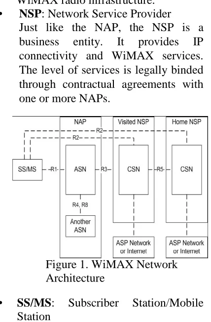
The WiMAX Network Architecture defines a framework consisting of several functional entities and interconnections. Figure1 shows this framework in simplified manner, followed by a description of each entity [INV07].
• NAP: Network Access Provider
A business entity that provides WiMAX radio infrastructure. • NSP: Network Service Provider
Just like the NAP, the NSP is a business entity. It provides IP connectivity and WiMAX services. The level of services is legally binded through contractual agreements with one or more NAPs.
Figure 1. WiMAX Network Architecture
Entity which wants to make a connection to the network.
• ASN: Access Service Network
This is the point of entry for the SS/MS into the WiMAX network. This entity must support a complete set of functions required to connect a client to the network: authorization, authentication, session management, network discovery, IP-address allocation, QoS etc.
• CSN: Connectivity Service Network
The CSN is the part of the network which provides IP connectivity services. It consists typically of routers, servers, proxies, and gateways etc.
providing functions like Internet access and peer-to-peer services.
Besides these entities the architecture also contains a number of interconnections or reference points. The most important and relevant ones are summarized here.
• R1: Protocols between SS/MS
and ASN
including PHY and MAC layers as specified by the 802.16 standard. •R2: Protocols/procedures between
SS/MS and CSN concerning authentication, authorization and IPconfiguration management.
• R3: Control procedures between ASN
and CSN. Provides tunnelling of user data between the two entities.
• R4: Control procedures between ANSs
like MS mobility between different ASNs.
•R5: Control procedures for supporting
roaming from a home NSP to a visited NSP.
• R8: When switching between different
BSs within the same ASN or between different ANSs (which most likely will also involve a switch between BSs) this is an optional reference point to ensure fast and seamless handover through direct transfer of MAC context and data.
Together, the technology and network architecture give a summarized and simplified view of WiMAX networks.
2.2 WLAN
WLAN is a very popular wireless communication technology for short/medium distances nowadays, mostly because it convenient, easy to deploy, easy to manage and because of its low infrastructure costs.
The Wireless Local Area Network (WLAN) is an unlicensed band of 802.11 ISM frequency band. 802.11 is one of the recent communication technologies of IEEE standard. It specifies medium access control (MAC) and physical layer that is why it is called Wireless LAN. It has three widely used types which operates on different frequency bands. These three types are 802.11a, 802.11b and 802.11g.
A typical WLAN network consists of Access Points (APs) and several wireless clients, called Stations (STAs). WLAN supports PMP mode and adhoc mode. Combinations are also possible; this is a so-called hybrid network.
Today, the standard 802.11g, generally referred to as Wi-Fi, has been implemented all over the world. For the remaining part of the paper, when WLAN is used, 802.11g is meant. Just like every other 802.x standard, the MAC and PHY layers are specified. Again, just like WiMAX, de physical layer specifies the modulation scheme used and signalling characteristics for the transmission through the radio frequencies, whereas the MAC layer defines a way accessing the physical layer [MET07].
2.2.1 Architecture
e.g. the Internet.
Furthermore, Wireless Local Area Network instigate as an overlay to the Wired Local Area Network. Lightweight and Autonomous are two discrete architectures used in WLAN environment. Each of the architectures has wide impact on wired LAN architecture. The selection of WLAN architecture is based on the consideration of building, future proof, integrated wired and Wireless LAN to accomplish high return on investment. Both architectures are popular but Lightweight architecture has plus advantages over the WLAN market. 2.2.2 Lightweight Model
Lightweight is the part of WLAN architecture. With most of wireless intelligence which residing at central controlling device, lightweight Wireless Access Point architecture have narrow functionality.
Figure2. Lightweight Architecture Model [BEM06]
Lightweight model is simple. The devices that provide the communication to the end user as Access Layer are identified by lightweight. Distribution layer provide the inter communication and the top layer (Core Layer) of Lightweight model is responsible fast and consistent data between networks.
Wireless Access Point (WAP) resides
at the interface of access layer and provides the communication interface to end user. In lightweight architecture model, the management of operation is easy because it give the permission to WAP from single device, because the lightweight WAP have the knowledge of visibility and attentiveness of the neighbours WAPs. They can observe and if any one of their neighbours becomes the victim of fault it notifies the wireless controller.
Lightweight WAP may be Self-healing because to pay compensation for unsuccessful counterpart, controller commands the neighbouring WAP to regulate their power level, where as in autonomous there is no concept of the visibility of its WAP neighbouring and in this case to perform self healing it cannot adjust the power level. If single WAP is busy or overloaded then in this situation wireless controller can relieve the wireless client to neighbouring WAP. In critical applications such as VoIP, self-healing and load
balancing are important issues. 2.2.3 Autonomous Model
In Autonomous Model WAP is not mandatory as shown in Figure. Autonomous Wireless Access Point sustains the switching and strong security as well as networking function that are indispensable to route the wireless traffic. As in autonomous system there is no concept of the visibility of WAP so it cannot make the load balancing.
Autonomous model cannot differentiate whether nearest WAP is part of WLAN infrastructure or illegal rouge WAP. The difference between the autonomous and lightweight is negligible. The difference is only this that lightweight have one extra component (WLAN controller) [BEM06].
2.3 HANDOVERS
has to move. Seamlessness in this paper is defined as follows: the current session, QoS and Service Level Agreements (SLA) must be maintained during and after handover. In other words, a seamless handover is a handover that is seamless to the user. Obviously this also depends on the kind of service the user is requiring. With real-time applications like videoconferencing or streaming media, the user will probably notice a decrease of the connection. On the other hand, while browsing a website or transferring a file, the user does not have to notice anything of the handover process. The latency and packet loss are the two crucial factors for seamless handover. These two factors have to be as small as possible to make the handover seamless [TTL99].
Before discussing several handover issues, the next part will go into detail about handovers in general first. There can be several reasons why and when a handover should be initiated [RAP06]: • MS current position and velocity
High velocity can result in different handover decisions.
• Link quality
Another BS can deliver a higher quality link (e.g. higher speed, stronger signal, better QoS).
• Load at a BS
When a BS in a subnet is currently overloaded; the network can decide to relocate some MSs.
• Conserving battery power
In order to save battery power, a MS can choose to switch to a closer station to be more energy efficient.
• Context and requirements
When a MS requires different type of service, it can be necessary to switch BS.
There are two types of handovers: horizontal (handovers within the same technology) and vertical (handovers between different network access technologies). Horizontal handovers are Layer-2 handovers (L2HO, also referred to
as ‘micro- mobility’). Here, only the BS is changed and IP-information is maintained. Typically this causes small latency and low packet loss. Vertical handovers are Layer-3 handovers (L3HO, also referred to as ‘macro-mobility’), it also changes the IP attachment point and so IP information is changed too. Because of these changes, latency and packet loss are significantly higher [HPF07]. Besides these differences, there are more problems to consider. This will be discussed in the following sections, starting with horizontal handovers.
2.3.1 Horizontal handover
SSs in WiMAX are referred to as Mobile Subscribers (MS). The difference between a SS and a MS is that a MS can change its BS with a handover mechanism when connected to the network. Both BS and MS can initiate the handover. In most of the cases, MS initiates the handover, because of one of the reasons mentioned in section 2.3. The only logical reason why the network (BS) initiates a handover is when a BS is getting overloaded. With this handover, only layer 2 is involved as the technology stays the same and thus the IP address stays unchanged.
Because WiMAX is based on OFDMA technology, a MS basically uses hard handover (HHO, break-before-make handover) when moving to another BS [SG+05]. During handover, all connections are broken at all layers and no context information is shared between BSs. Therefore, the MS cannot receive and/or transmit any data during handover and packet loss occurs. Latency is on the order of around 1000 ms (milliseconds) or more [SG+05]. This is why seamless handover cannot be realized in this case. But besides hard handover, recent WiMAX standard also supports soft handover (SHO, make-before-break) and Fast BS Switching (FBSS), both supporting seamless handover. These solutions, and on other, will be clarified in section 3.1.
These handovers are more complex because they involve both L2HOs and L3HOs. WiMAX and WLAN use different protocols, different air technologies and have different QoS. Besides these differences there are similarities on some level. Both specify the MAC and PHY layers and use IP-technology to identify the network entities. This is why Mobile IP is developed, and used most of the times to support handovers between different technologies [TTL99] [RMB06] [JRJ07].
Because of the switch of technology, the MS enters another subnet, so its IP address changes too. This can be done in several ways, as the number of solutions in section 3.2 shows.
3. WIMAX/WLAN HANDOVER
SOLUTIONS
A lot of research is already done in the field of handovers. With the new and promising wireless broadband solutions, the capability to support fast and reliable handover is critical for its success. Most solutions provide extensions and/or improvements of the current standards in order to improve certain aspects.
Hereafter, several solutions will be introduced and briefly explained how they work. Of course, these are only a few of the ones available. The solutions will be divided into their applicability; horizontal or vertical handovers.
3.1 Horizontal handover solutions
The WiMAX standard, see [IEEE2] [HPF07], defines three basic handover protocols: Hard Handover (HHO), Soft Handover (SHO) and Fast BS Switching (FBSS). These will be explained here. After that, another solution will be discussed: Enhanced ARP Handover. 3.1.1 Hard Handover
The WiMAX standard specifies the general HHO process as stated in figure 4
[LKU06]. Before handover initiation, the MS and serving BS conduct network topology acquisition, backed up by the backbone network. BS broadcasts the network topology information for a period
of time using MAC message
transmissions. These messages contain network information about neighbouring BSs. Then MS is able to select a candidate BS for handover through scanning. After this, MS associates with candidate target BSs. MS records the obtained information so it can be used for future handovers.
After the topology acquisition, the handover process is performed as follows. MS conducts cell reselection based on the acquired information of the network. Then target BS is decided and handover is initiated. MS synchronizes with new downlink and obtains uplink parameters. Initial ranging process is executed; this may be done contention-based or non-contention based.
Figure 4. WiMAX hard handover process [LKU06]
SHO (Soft Handover, make -before-break handover) is similar to HHO but with one major difference; with SHO a MS is registered to multiple BSs (the Active Set) at the same time. During SHO two or more BSs are sending and receiving the same information to the MS. This way, seamless handover is possible but it is utilizes more resources, see [SG+05]. 3.1.3 Fast BS Switching (FBSS)
With FBSS, the MS is only sending/receiving data to/from one of the BSs in the Active Set. The BSs in the Active Set communicate through the backbone network
to share context information. Based on this context information, handover decisions are made and handovers initiated. Again, seamless handover is possible but more network resources are used [SG+05]. But compared to SHO, fewer resources are used at the MS, because it is connected with only one BS at a time.
3.1.4 Enhanced ARP Handover
ARP stands for Address Resolution Protocol, see [IETF1], which is a very old draft. During the years, several improvements are proposed. It is a protocol which can be used within a subnet to map an IP address to the corresponding MAC address of the device. Then, this address is used to send packets to. This handover solution is an enhanced version of the original ARP protocol. In WiMAX, BSs can act as an ARP proxy in their cell. The BSs send out beacons and buffers packets for an MS. When an MS receives a stronger beacon from another BS, a handover is initiated. Figure 5 shows the handover [TTL99]. This handover process follows the steps described next:
1. MS sends greet-message to new BS with its own address and the address of the old BS.
2. New BS sends an acknowledgement and creates a routing entry for MS. 3. New BS sends notify-message to old
BS together with its address.
4. Old BS deletes MS’s entry and sends buffered packets to new BS along with a notify-ack-message.
5. New BS broadcasts a redirect message to routers to
update the ARP cache.
Because of the limitations of this handover solution to the same subnet, it can only be used for horizontal handovers. Nonetheless, it is a very fast handover technique which claims to complete handover in less than 10 ms [TTL99].
Figure 5. Enhanced ARP Handover [TTL99]
3.2 Vertical handover solutions As stated before, vertical handovers are more complex compared to horizontal handovers. There are several solutions available in literature, but none of them are standardized yet. In this case, vertical handover solutions are applied to WiMAX/WLAN handovers but can sometimes be used in other handovers as well.
3.2.1 Mobile IP
it acquires a care-of-address (COA), which uniquely identifies the MS in the foreign network. This COA is registered at the MS’s HA on the MS’s home network. Traffic is then tunnelled by the HA to the COA of the MS. This way, the change of IP address of the MS is hidden, in order to keep all TCP connections (Telnet, FTP etc.) alive.
This can be done in several ways. Mobile IPv4 basically uses triangular routing, see Figure 6. The MS sends data directly to the corresponding host (CH), whereas data for MS is send through the HA and the FA. The total process takes time and suffers from latency and packet loss. Also, because of triangular routing, packets are sending along paths which can be much longer and therefore less efficient. Mobile IPv6 benefits both from the experiences gained from the development of Mobile IP support in
Figure 6: Mobile IP triangular routing
IPv4 and from the opportunities provided by IPv6. Thus, Mobile IPv6 shares many features with
Mobile IPv4 but it also offers many improvements. The biggest benefit is the support for route optimization. It uses binding updates to inform the CH about the current IP address of the MS so traffic can be sent directly to the MS. Other improvements are described in [IETF3] but will not further be discussed here. 3.2.2 IP Multicast
The IP protocol provides three types of communication: unicast (sending data to a single receiver), broadcast (sending data to all the receivers on a given network) and multicast (deliver the data to a set of selected receivers). In IP Multicast only a single packet is sent by the source.
The network duplicates this packet until all the intended BSs receive the packet. The BSs buffer these packets. The serving BS will forward it to the MS it is meant for. When a handover is initiated, a MS messages to both
old and new BS and the new BS starts to forward the packets to the MS, see [TTL99] [RMB06].
3.2.3 MIH
MIH stands for Media Independent Handover. It is an interworking standard, IEEE 802.21, see [IEEE5], which is being developed to support handovers between any wireless access technologies [DJW07]. MIH defines an extra layer between Layer 2 (IP Layer) and Layer 3 (wireless link layer) in the protocol stack. See Figure 5 for a graphical representation. The MIH layer facilitates messaging among IP and the various wireless
technologies in order to select the appropriate network for handover.
Figure 7. The MIH Function [DJW07]
As can be seen in Figure7, the MIH layer can convey three types of messages: • Events
A lower layer informs a higher layer of an event. Examples are: wireless link quality degrading and handover status.
• Commands
The two layers exchange information. Examples: current QoS, performance information and availability of services.
The standard specifies these messages for different handover combinations. This way, different technologies can communicate efficiently through the MIH layer [DJW07].
3.2.4 FMIPv6
One of the disadvantages of Mobile IP handover is high latency. This latency is defined as the time frame in which the MS is unable to send or receive any packets because of link switching and IP reconfiguration. FMIPv6 stands for Fast Mobile IPv6 Handover see [IETF4]. It is an improved solution of the Mobile IP protocol. Fast Handover provides seamless handover using IPv6 address space and a Layer 2 trigger [PaC03]. Figure 8 shows the operation of the FMIPv6 handover protocol.
Either MS or Old BS may initiate the handover procedure by using the L2 trigger. If MS initiates and old BS receives the trigger, the MS will initiate L3 handover by sending a Router Solicitation for Proxy (RtSolPr) message to the old BS. Otherwise, if old BS initiates, it sends a Proxy Router Advertisement (PrRtAdv) to the MS.
After this, the MS must obtain a new COA, just like with Mobile IP. The difference here is that MS is still connected to the old BS. The old BS validates the new COA and establishes a connection tunnel between old and new BS by sending a Handover Initiate (HI) message. The new BS verifies the new
COA and sends a Handover
Acknowledgement (HACK).
Before disconnecting, the MS should send a Fast Binding Update (F -BU) to update the binding cache with the new COA. When the old BS receives the F-BU message, it must verify the handover with the new BS. Then it begins forwarding
packets from the old COA to the new BS. When the MS connects to the new BS, the new BS starts sending packets to the M S and the handover is completed [PaC03]. 3.2.5 HMIPv6
HMIPv6 is Hierarchical Mobile IPv6 Mobility Management, see [IETF5]. Also, this is an improved solution of the Mobile IP protocol. Hierarchical schemes reduce handover latency. It does so by employing a hierarchical network structure. This structure separates mobility into micro- and macro mobility (see section 2.3). To support this, a special network entity is placed into the edges of the network: the Mobile Anchor Point (MAP).
Figure 8. Fast Mobile IPv6 Handover Protocol [PaC03]
the MAP in order to bind MS’s regional COA to the on -link COA. In addition, the MS sends BUs to its HA and the CNs in order to specify the binding between its home address and the regional COA. 3.2.6 SIP
Session Initiation Protocol, see [IETF6], is an application-layer protocol used to establish and tear down multimedia sessions [WeS99]. Because SIP is a protocol which is handled at the application layer, there is no need for tunnelling of the data stream.
Entities in SIP are users, proxy servers and redirect servers. A user is addressed using an e-mail-like address, e.g. user@hos where ‘user’ is obviously the user and ‘host’ is the domain name. Data is exchanged during the session in some sort of peer-to-peer mode [JRJ07]. SIP defines a number of methods, see table 1.
A SIP user has two functions: listening for SIP messages and sending SIP
messages upon occurring events. The proxy server relays SIP messages, so the use of host names is possible without knowing the IP address. A redirect server returns the location of the host. Both proxy servers and redirect servers accept user registrations, in which the current location of the user is given. If a user goes mobile during a session, it must send a new INVITE to the corresponding host using the same call identifier as in the original call. It should send the new IP address or host name, so the
corresponding host knows where to send the SIP messages to. Also, the mobile user has to reregister the new location to the proxy- and redirect servers.
TABLE1. SIP messages [WeS99]. Message
name Function
INVITE Invite user(s) to a session.
ACK Acknowledgement of an
INVITE message
BYE Release session.
OPTIONS Asks server capabilities.
CANCEL Cancel pending request
[JRJ07] proposes an improvement of the standard SIP protocol. It uses constant destination identifiers so the user does not have to re-invite the correspondent host. Sessions do not need to be terminated every time. The user updates the registry at the SIP servers and packets from the CH are automatically sent to the user.
4. HANDOVER SOLUTION COMPARISON
In order to compare the solutions, a list of criteria is necessary to review each solution. The following list of criteria will be used to compare the solutions:
• Handover latency.
How much time does it take to complete the handover? Solutions are compared based on the time it takes to complete the handover. Obviously, less latency is better.
• Handover type.
Which type of handover is supported by the solution? In this case the only to types relevant are seamless or non-seamless handovers.
• Complexity.
How complex is the solution?
This is measured in terms of the number of needed entities, protocol layers and/or hardware requirements. • Dropped packets.
During handover, packet loss is inevitable. Of course, there is a difference in the number of dropped packets. Again, obviously, less packet loss is better.
• Scalability.
Is the solution applicable with a large number of users? How does this scalability influence the performance? Performance must be maintained as much as possible when more users are added to the domain.
It is important to note that the performance results used in the given comparisons are taken from different papers that each described the different solutions separately. This means that the used network topologies and settings are different and therefore, the performance related comparison given in the following sections could be inaccurate.
4.1 Horizontal Handover SolutionComparison
In this section, horizontal handover solutions will be compared based on the proposed criteria. This will be done by discussing each solution. To provide a clear overview of the differences and in order to make a good comparison, a table is introduced. This table is set up as follows: solutions are placed in rows and the criteria will be put in the columns. To compare the solutions and review them, values are introduced: high, medium and low. In this case, there’s no general good or wrong, but each value must be read within the right perspective. For example: the value ‘high’ for the criteria ‘Handover Latency’ is not good, whereas this value for ‘Scalability’ means the solution scores well. For handover type there are two types: non-seamless; N-S and seamless; S.
Table2 gives an overview of the comparison of horizontal handover solutions. Thereafter, the table will be clarified in the discussion, with an explanation of the choices made.
4.1.1 HHO
According to [LKU06] the HO operation time with HHO and no further improvements lies between 700 ms and 900 ms. This depends mainly on the
cell-load, where 700 ms is reached with a cell load of 0% and 900 ms with a cell load of 50%, see [LKU06]. The handover type is non-seamless because it uses a break-before-make handover. Complexity is low because the HO process is pretty straightforward with just two BSs (old and new) and the MS. Because of the break-before-make nature, it is very likely that packets sent to MS
TABLE2: Horizontal handover solution comparison[JD+08]
nc
yH
an
do
ve
r Type
H
an
d
ov
er
C
o
m
p
le
x
ity pped tsDro packe onati uplic fDso y abilit Scal
HHO high N-S low high low high
SHO med S med med med med
FBSS low S med low low med
ARP low S low low Low high
are dropped because the MS cannot receive any packets during handover. There is no duplication of events, the BSs do not share any context information and MS just sends/receives packets from one BS. Finally, because of the low complexity of the solution, it is scalable; with its limitations in the number of MSs one BS can
serve. But compared to other solutions where BSs have to do a lot more and are overload faster, this solution is scalable. 4.1.2 SHO
relatively large and thus can be noticed by the user. Complexity is also medium, there are more entities involved with the handover. The Active Set contains more BSs compared to the number of BSs with HHO and because the make-before-break nature, the handover process is more complex. Obviously there are less dropped packets because handover is seamless. MS is registered at multiple BSs. Because of this, there is some duplication of events. Last, the solution is scalable just like HHO, but because BSs have to keep more MSs registered, they overload sooner. 4.1.3 FBSS
Fast Base Station Switching is like SHO but because it uses fast-ranging and context sharing, latency is further reduced. According to [SG+05], values vary between 50 and 100 ms, therefore seamless handovers can be supported. Complexity is generally medium, just like the size of the used buffer based on the number of connected MSs.
4.2Vertical handover solution comparison
This section will elaborate about the comparison of vertical handover solutions. The structure of the section will be the same as section 4.1. First, a table is provided to give a clear overview of the comparison, followed by a detailed discussion to explain how the values are justified.
4.2.1 Mobile IP
Due to the fact that Mobile IP uses the HA in the data communication, the Mobile IP latency can be in some situations significant. Without any improvements, and according to [HS+02], the handover latency can reach 5000 ms. The handover is seamless because the IP session is maintained, but it will definitely not go unnoticed by the user. Mobile IP uses a rather complex construction with the HA and COA. Because of the high handover latency, and long paths from CH to MS, the packet dropping probability is high. Because all traffic is tunnelled through the HA, the COA is added to each packet
which causes a lot of overhead, even up to 25%.
This is not really ‘duplication of events’ but surely decreases efficiency. Every MS uses its own HA and acquires its own COA. This might affect the scalability negatively.
SHO, but there is a difference. Complexity at the MS is lower than with SHO, because MS is connected to just one BS. But at the BSs, complexity is slightly higher because they have to share context information about the MSs through the backbone network. But this context sharing combined with lower handover latency also limits packet dropping. Duplication of events is low because BSs communicate current states of MSs through the backbone network, reducing redundancy. Just like with SHO, scalability depends on the BSs. They tend to get overloaded with too much of MSs connected. When this happens, too much background
The MIH layer takes care of communication between the upper and lower layer, resulting in a very efficient solution and minimal duplication of events. Also, the solution is highly scalable since it uses no extra network entities but only an additional layer which is used by all users.
4.2.4 FMIPv6
Fast Mobile IPv6 Handover has improvements regarding regular Mobile IPv6. According to [PaC03], it reduces handover latency to 350 ms. Because of smarter routing; the solution itself is less complex compared to Mobile IP. But these improvements come at extra costs in terms of overhead and signalling costs. Thus, the improvements cause more duplicated events. Scalability can be considered medium, just like the other Mobile IP solutions.
4.2.5 HMIPv6
[HS+02], takes approximately 700 ms to complete. There is an extra physical entity introduced on the edges of the network, the MAP. Next to the MAP, also two COA addresses are needed. This makes the solution more complex compared to IP Multicast but less complex then the MIH or Mobile IP solutions. The same counts for packet-loss. Because of lower latency and less complexity, packet-loss is medium. During handover, duplication of events can occur. It is possible that the new MAP already starts sending packets to the MS while the old MAP is transferring its last, when MS has not informed the old MAP of re-registration. Scalability in this case depends on the number of MAPs, of course with respect to the implementation costs.
4.2.6 SIP
When a MS uses SIP and moves to another domain, the only thing the MS has to do is to re-register at the SIP server. Because of this, the handover delay can be very low. According to [JRJ07], around 50 ms. The direct connection to the CH is maintained through the SIP server, so handover is seamless. SIP is just an application protocol and thus not complex at all. The low latency in this solution means low packet-loss. Scalability is high since redirect servers are used. A redirect server returns the location of the MS. This makes it possible to build highly scalable servers, because these servers only have to return the location of the MS instead of participating in the entire transaction.
5. CONCLUSIONS AND FUTURE WORK
This paper focused on seamless handover. As wireless technologies are emerging, there is a need to be always best connected. This cannot be done without the possibility to roam between different networks and different wireless technologies. The process which facilitates this is called a handover.
As the most promising new wireless access technology, the research first
focused on WiMAX. After exploring the technical details of WiMAX, several horizontal handovers were introduced: Hard Handover, Soft Handover, Fast Base Station Switching and Address Resolution Protocol.
Besides this promising technology, another, very popular technology was considered; WLAN. A combination of WiMAX and WLAN would be ideal in terms of combining the strong aspects of both technologies. That is why vertical handovers between these two technologies were also researched. Here, vertical handover (handover between different technologies) solutions are: Mobile IP, IP Multicast, Media Independent Handover (MIH), Fast Mobile IPv6 Handover (FMIPv6), Hierarchical Mobile IPv6 Mobility Management (HMIPv6) and Session Initiation Protocol (SIP).
All these solutions were reviewed based on a number of criteria. Those criteria are: handover latency, handover type, complexity, dropped packets, duplication of events and scalability.
As a result of this comparison, several conclusions can be drawn. In this paper, the ARP Handover has the best overall score. In case of vertical handover, this is not so easy. There are more issues to consider and different solutions can have several advantages.The solutions which provide the best handover performance is a combination of several. This is backed up by research papers like [HPF07], [SG+05], [LKU06] and [BMN07]. An example is the MIPv6 combined with HMIPv6 and the fast handover mechanism of FMIPv6.
Further research in this area is, logically, to find out how these solutions can work together in an effective and efficient way.
REFERENCES
Networks, Q.B. Mussabbir, W. Yao, Z. Niu, X. Fu, IEEE Transactions on Vehicular Technology vol. 56, issue 6, part 1, Nov. 2007, pp. 3397 – 3407
[BEM06] Bob Elliot, Elsa Mardrigal; ”Choosing the right WLAN Architecture”,
www.panduit.comhttp://www.pand uit.com/groups/MPMW
C/documents/Article/107242.pdf, June 2006.
[CFL04] Spectrum modelling of OFDM signals for WLAN, C. Liu, F. Li, Electronics Letters vol. 40, Issue 22, Oct. 2004 pp. 1431 – 1432. [DJW07] Maintaining QoS During
Handover Among Multiple
Wireless Access Technologies, D. Wright, 6th International Conference on the Management of Mobile Business, 9-11 July 2007, pp. 10-18.
[FYW07]Mobile IPv6 Mobility
Management in Integrated Wi-Fi and WiMAX Networks, S. Yang, J. Wu, IEEE 65th Vehicular Technology Conference, April 2007, pp. 1152-1156.
[HPF07] On the Evolution of Handoff
Management and Network
Architecture in WiMAX, R. Q. Hu, D. Paranchych, M. Fong, G. Wu,
IEEE Mobile WiMAX
Symposium, March 2007, pp. 144-149.
[HS+02] Performance analysis on hierarchical Mobile IPv6 with fast-handoff over end-to-end TCP, R. Hsieh, A. Seneviratne, H. Soliman, K. El- Malki, IEEE Global Telecommunications Conference vol. 3, Nov. 2002 pp. 2488- 2492 [IEEE1] IEEE 802.16-2004, IEEE
Standard for Local and metropolitan area networks Part 16: Air Interface for Fixed Broadband Wireless Access Systems.
[IEEE2] IEEE 802.16e-2005, IEEE Standard for Local and
metropolitan area networks Part 16: Air Interface for Fixed and Mobile Broadband Wireless Access Systems Amendment for Physical and Medium Access Control Layers for Combined Fixed and Mobile Operation in Licensed Bands.
[IEEE3] IEEE 802.11, IEEE Standards for
Information Technology
Telecommunications and
Information Exchange between Systems, Local and Metropolitan
Area Network, Specific
![Figure 4. WiMAX hard handover process [LKU06]](https://thumb-us.123doks.com/thumbv2/123dok_us/7826573.1296863/6.595.322.538.474.651/figure-wimax-hard-handover-process-lku.webp)
![Figure 5. Enhanced ARP Handover [TTL99]](https://thumb-us.123doks.com/thumbv2/123dok_us/7826573.1296863/7.595.321.526.282.489/figure-enhanced-arp-handover-ttl.webp)
![Figure 8. Fast Mobile IPv6 Handover Protocol [PaC03]](https://thumb-us.123doks.com/thumbv2/123dok_us/7826573.1296863/9.595.317.539.330.507/figure-fast-mobile-ipv-handover-protocol-pac.webp)
