Kinematic Car Model Driven by Actuators
Kavya Sree Chandran1, Arun S Mathew2PG Student, Dept. of EEE, Mar Baselios College of Engineering & Technology, Trivandrum, Kerala, India1
Assistant Professor, Dept. of EEE, Mar Baselios College of Engineering & Technology, Trivandrum, Kerala, India2
ABSTRACT:Kinematic bicycle model is a common approximation used for vehicle analysis and for deriving control laws. It approximates the mobility of the car. The vehicle model is represented in terms of its position in xy coordinates, orientation with respect to x axis and the steering wheel angle. This model has two inputs, one is the linear velocity required for the forward motion of the vehicle and other is the steering angle for the direction changes. In this paper two actuators are used to provide inputs to the model in order to drive the vehicle. A PID controlled DC motor is one of the actuator that gives the linear velocity input and a PID controlled Stepper motor is the other one that outputs the steering angle. Matlab/Simulink software is used for simulations throughout the work.
KEYWORDS: Kinematic bicycle model, PID, DC motor, Stepper motor, Steering angle.
I.INTRODUCTION
A commonly used model for a four-wheeled vehicle is the kinematic bicycle model. The kinematic bicycle model, as the name indicates looks like a bicycle. This model approximates the front two wheels into a single wheel and similarly the back two wheels into a single one at the centre of front and rear axles.
A separately excited DC motor is used to provide forward moving speed for the vehicle. In separately excited DC motor both field magnet and armature have seperate power supply. Two types of Seperately excited DC motors are Armature controlled DC motor and Field controlled DC motor. An Armature controlled DC motor has its field current constant and the motor torque is controlled by armature current, the speed of motor is varied by changing armature voltage in the constant torque region. In Field controlled DC motor the armature current is constant and field current controls the motor torque. In general the separately excited DC motor has independent control over supply voltage and magnetic flux and this allows the setting of the required torque at any angular speed with greater flexibility.
Stepper motor act as steering motor and gives the angle to which steering has to be rotated. Stepper motors have a central gear-shaped iron piece surrounded by multiple toothed electromagnets. An external driver is required to energize the electromagnets. The working is as follows: first, power is given to one of the electromagnet and it attracts the gear's teeth magnetically towards it. When the next electromagnet is powered, the first one is turned off and the gear rotates to align with the next one and this process continues. This is how the motor shaft turns and each of these rotations are known as a step. There are three basic types of stepper motors: Permanent magnet(PM), Hybrid and Variable reluctance(VR) stepper motor. Permanent magnet motors have a permanent magnet as the rotor and electromagnets as stator. They operate based on the attraction or repulsion between the rotor and the stator. In variable reluctance motors, a plain iron is used as rotor and they operate in such a way, so that minimum reluctance occurs with minimum gap, and the rotor points are attracted toward the stator magnet poles. Hybrid stepper motors are a combination of PM and VR motors and have maximum power in a small package size.
II.
KINEMATIC BICYCLE MODELThe kinematic model equation is given below:
̇ =
̇ =
̇ =
̇ = ---(1)
where (x,y) = position of vehicle in xy plane, = vehicle heading angle relative to x-axis, = vehicle steering angle, L = distance between front and rear wheel axles, = linear driving velocity input and = steering angular velocity input.
The two velocity inputs u1 and u2 are the variables available for motion control. It is assumed that the wheels have no
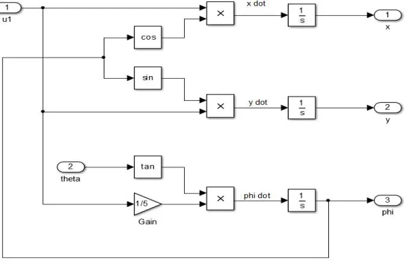
lateral slip and only the front wheel is steerable.The Mathematical model representation of kinematic bicycle model in Matlab/Simulink is presented below.
Fig. 1 Vehicle Kinematic Simulink model
III.ACTUATORS
Figure below shows the simplified equivalent circuit representation of armature controlled separately excited DC motor.
The equivalent circuit consists of two independent circuits, armature circuit and field circuit. The loads are connected to the armature circuit as shown in the figure. The mathematical model of the motor consists of electrical and mechanical equations describing its physical properties. The equations are
i. The armature circuit equation:
= + + − − − − − − − − − − − − − − −(2)
where, Vt = applied terminal voltage to the motor or armature voltage in Volt, Eb = emf induced in the armature
winding or back emf in Volt, La = armature inductance in Henry, ia = armature current in Ampere and Ra = armature
resistance in Ohm.
ii. Back emf equation:
= − − − − − − − − − − − − − − − − − − − − − − −(3)
where, = motor constant, k = machine constant, = magnetic flux and = motor speed in rad/sec.
iii. The equation of mechanical part:
= = + + − − − − − − − − − − − − −(4)
where, = electromagnetic torque in Nm, J = moment of inertia in kgm2, B = viscous friction coefficient in Nm-sec and = Load torque in Nm.
The block diagram of the mathematical model of DC motor described in equation(2), (3) and (4) implemented in Matlab/Simulink is presented in Figure 3.
The stepper motor transfer function used for simulation is 3.839/(0.004s2+0.34s+1).
IV.OVERALL SYSTEM
The block diagram of overall system is shown below.
Fig. 4 Block diagram of proposed system
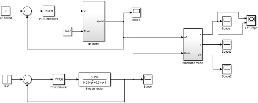
Figure below shows the simulink block of the overall system with a reference linear velocity of 9m/s and reference steering angle of 0.5 radians.
Fig. 5 Simulink representation of overall system
V. SIMULATION RESULTS
The specifications of DC motor used for simulations are Vt = 230V, Tload = 100Nm, La = 0.0065H, = 4.212, Ra =
Fig. 6 Linear velocity input of kinematic model
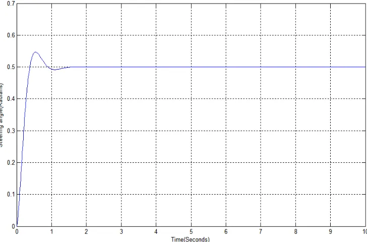
Fig. 7 Steering angle input of kinematic model
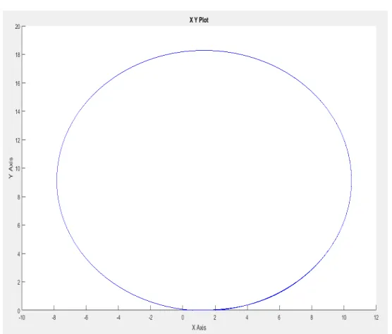
Fig. 8 Path traced by the kinematic car model
VI.CONCLUSION
This paper presents a kinematic car model driven by actuators. Separately excited dc motor and stepper motor are the actuators used. PID controller is implemented to control the speed and position of motors. The controlled linear velocity and rotor position is provided as input to the kinematic car model. The path traced by the car model is same as the expected trajectory.
REFERENCES
[1] Mohammed Ahmed, Mehmed Yu ksel, “Design and Implementation of a Path Tracking Steering Controller for EO Smart Connecting Car” in
Proc. Of World Cong. on Multimedia and Computer Science, 2013.
[2] Jarrod M. Snider, “Automatic Steering Methods for Autonomous Automobile Path Tracking” Robotics Institute Carnegie Mellon University
Pittsburgh, Pennsylvania, February 2009.
[3] Guoqiang Chen & Xianguang Shang, “Simulation used in education for a separately excited DC motor”, World Transactions on Engineering
and Technology Education , Vol.12, No.1, 2014.
[4] Ibrahim Al-Abbas, Rateb Issa and Hussein Sarhan, “Separately Excited DC Motor Parametric Control Using Electronic Workbench”,
International Journal of Engineering Research and Development, Volume 2, Issue 3, PP. 51-58, July 2012.
[5] Waleed I. Hameed and Khearia A. Mohamad, “Speed Control of Separately Excited DC Motor Using Fuzzy Neural Model Reference
Controller”, International Journal of Instrumentation and Control Systems (IJICS) Vol.2, No.4, October 2012.
[6] Aniket B. Kabde and A. Dominic Savio, “Position control of stepping motor”, International Journal of Advanced Research in Electrical,
Electronics and Instrumentation Engineering, Vol. 3 issue 4, April 2014.
[7] Bindeshwar Singh, R.P. Payasi, K.S. Verma, Varun Kumar, and Satyarth Gangwar, “Design of Controllers PD, PI &PID for Speed Control of
DC Motor Using IGBT Based Chopper”, German Journal Of Renewable And Sustainable Energy Research (GJRSER),Vol. 1, Issue.1, pp.
29-49, 2013.
[8] Aditya Pratap Singh, Udit Narayan and Akash Verma, “Speed Control of DC Motor using Pid Controller Based on Matlab”, IISTE , Vol.4,