International Journal of Scientific Research in Computer Science, Engineering and Information Technology © 2017 IJSRCSEIT | Volume 2 | Issue 3 | ISSN : 2456-3307
Gesture Controlled Bot
Mitali Daga, Chandrakant Sahu, Tabassum Khan, Ruchi Soni, M. Vishal Kumar, Nainika Singh
Rathore, Shailendra Singh
Department of Electronics and Telecommunication, Student of RSR- RCET, Bhilai, Chhattisgarh, Punjab, India
ABSTRACT
A robot is usually an electro-mechanical machine that is guided by computer and electronic programming machine . Many robots have been built for manufacturing purpose and can be found in factories around the world. Designing of the latest inverted ROBOT which can be controlling using an Accelerometer based gesture controlled Bot using microcontroller. The proposed electronics system recognizes a particular hand gesture that will be performed in front of webcam & transmitted respected signals wirelessly through RF module. Depending on the received signals the robotic arm which is followed by AVR microcontroller performs the receptive motions at the receiver section. This robots can be reprogrammable and can be interchanged to provide multiple applications.
Keywords : Hand Gesture , AVR Microcontroller , Embedded System.
I.
INTRODUCTION
During the last some decades, with the increase in population and economic transition, the use of electronics in India have changed in a significant way. With the increasing urbanization, industrialization, motorization and changing lifestyles large number of inventions have been made. Lets discuss something related with Embedded Systems.
A gesture controlled robot using an accelerometer is one kind of robot which can be operated by the movement of hand by placing an accelerometer on it. This project is divided into two parts transmitter device and receiver device. Where a gesture device works as a transmitter device and a robot works as a receiver device.When a transmitting device (accelerometer) is placed on the hand, then it will send signals to the robot for the required operation.
Embedded Systems
An Embedded System is a combination of computer hardware and software, and perhaps additional mechanical or other parts, designed to perform a specific function. An embedded system is a microcontroller-based, software driven, reliable, real-time control system,
autonomous, or human or network interactive, operating on diverse physical variables and in diverse environments and sold into a competitive and cost conscious market.An embedded system is not a computer system that is used primarily for processing, not a software system on PC or UNIX, not a traditional business or scientific application. High-end embedded & lower end embedded systems. High-end embedded system.
Advantages are Unmanned robotics and gesture controlled robotic devices are being actively developed for both civilian and military use to perform a variety of dull dirty and dangerous activity . In many application of controlling robotic gadget it becomes quite hard and complicated when there comes the part of controlling it with remote or many different switches. The concept of using gestures to control machine with the movement of hand which will simultaneously control the movement of robot which is a benefit.Cost of production is very cheap.
Design and Implementation
can be found in factories around the world. A Gesture Controlled robot is a kind of robot which can be controlled by your hand gestures not by old buttons.You just need to wear a small transmitting device in your hand which included an acceleration meter.This will transmit an appropriate command to the robot so that it can do whatever we want. The transmitting device included a comparator IC for analog to digital conversion and an encoder IC(HT12E) which is use to encode the four bit data and then it will transmit by an RF Transmitter module.
At the receiving end an RF Receiver module receive's the encoded data and decode it by an decoder IC(HT12D). This data is then processed by a microcontroller (P89V51RD2) and finally our motor driver to control the motor.
II.
METHODOLOGY
The task performed step by step are as follows:-
1. P.C.B. Layout
The entire circuit can be easily assembled on a general purpose P.C.B. board respectively. Layout of desired diagram and preparation is first and most important operation in any printed circuit board manufacturing process. First of all layout of component side is to be made in accordance with available components dimensions.
The following points are to be observed while forming the layout of P.C.B.
Between two components, sufficient space should be maintained.
High voltage/max dissipated components should be mounted at sufficient distance from semiconductor and electrolytic capacitors. The most important points are that the
components layout is making proper compromise with copper side circuit layout. Printed circuit board (P.C.B.s) is used to
avoid most of all the disadvantages of conventional breadboard. These also avoid the use of thin wires for connecting the components; they are small in size and efficient in performance.
2. Preparing Circuit Layout
First of all the actual size circuit layout is to be drawn on the copper side of the copper clad board. Then enamel paint is applied on the tracks of connection with the help of a shade brush. We have to apply the paints surrounding the point at which the connection is to be made. It avoids the disconnection between the leg of the component and circuit track. After completion of painting work, it is allowed to dry.
3. Drilling
After completion of painting work, holes 1/23 inch(1mm) diameter are drilled at desired points where we have to fix the components.
4. Etching
After etching, the P.C.B. is kept in clean water for about half an hour in order to get P.C.B. away from acidic, field, which may cause poor performance of the circuit. After the P.C.B. has been thoroughly washed, paint is removed by soft piece of cloth dipped I thinner or turbine. Then P.C.B. is checked as per the layout.
5. Soldering
Soldering is the process of joining two metallic conductor the joint where two metal conductors are to be join or fused is heated with a device called soldering iron and then as allow of tin and lead called solder is applied which melts and converse the joint. The solder cools and solidifies quickly to ensure is good and durable connection between the jointed metal converting the joint solder also present oxidation.
6. Soldering And Desoldering Techniques
These are basically two soldering techniques. Manual soldering with iron.
Mass soldering.
7. Soldering With IRON
The surface to be soldered must be cleaned & fluxed. The soldering iron switched on and bellowed to attain soldering temperature. The solder in form of wire is allied hear the component
to be soldered and heated with iron. The surface to be soldered is filled, iron is removed and joint is cold without disturbing.
8. Solder Joint are Supposed To
Provide permanent low resistance path.
Make a robust mechanical link between P.C.B. and leads of components.
Allow heat flow between component, joining elements and P.C.B.
Retain adequate strength with temperature variation. The following precaution should be taken while
soldering:
Use always an iron plated copper core tip for soldering iron.
Slightly for the tip with a cut file when it is cold. Use a wet sponge to wipe out dirt from the tip before
soldering instead of asking the iron.
Tighten the tip screw if necessary before iron is connected to power supply.
Clean component lead and copper pad before soldering.
Apply solder between component leads, P.C.B. pattern and tip of soldering iron.
Iron should be kept in contact with the joint for 2-3 seconds only instead of keeping for very long or analog data while moving in X,Y,Z direction or may be X,Y direction only depend's on the type of the sensor.Here is a small image of an Accelerometer shown. We can see in the image that their are some arrow showing if we tilt these sensor's in that direction then the data at that corresponding pin will change in the analog form.
The Accelerometer having 6 pin-
2- GND- We simply connect this pin to the ground regulators include some automatic protection from excessive current (over load protection) and overheating (thermal protection). Many of fixed voltage regulator ICs has 3 leads. They include a hole for attaching a heat sink if necessary.
Figure 4. Voltage Regulator
3) DESCRIPTION
These voltage regulators are monolithic circuit integrated circuit designed as fixed voltage regulators for a wide variety of applications including local, on card regulation. These regulators employ internal current limiting, thermal shutdown, and safe-area compensation. With adequate heat sinking they can deliver output current in excess of 1.0 A. Although designed primarily as a fixed voltage regulator,
these devices can be used with external components to obtain adjustable voltage and current.
4) FEATURES
1. Output current in Excess of 1.0 A 2. No external component required 3. Internal thermal overload protection 4. Internal short circuit current limiting 5. Output transistor safe-area compensation 6. Output voltage offered in 2% and 4% tolerance 7. Available I n surface mount D2PAK and
standard 3-lead transistor packages Previous commercial temperature range has been extended to a junction temperature range of -40 degree C to +125 degree C.
5) POWER SUPPLY
The circuit uses standard power supply comprising of a step-down transformer from 230Vto 12V and 4 diodes forming a bridge rectifier that delivers pulsating dc which is then filtered by an electrolytic capacitor of about 470µF to 1000µF. The filtered dc being unregulated, IC LM7805 is used to get 5V DC constant at its pin no 3 irrespective of input DC varying from 7V to 15V. The input dc shall be varying in the event of input ac at 230volts section varies from 160V to the transformer delivers 12V at 220V input it will give 8.72V at 160V.Similarly at 270V it will give 14.72V.Thus the dc voltage at the input of the regulator changes from about 8V to 15V because of A.C voltage variation from 160V to 270V the regulator output will remain constant at 5V.
6) MICROCONTROLLER
Features
• High-performance, Low-power AVR 8-bit Microcontroller
• Advanced RISC Architecture
– 131 Powerful Instructions – Most Single-clock Cycle Execution
– 32 x 8 General Purpose Working Registers – Fully Static Operation
– Up to 16 MIPS Throughput at 16 MHz – On-chip 2-cycle Multiplier
• Nonvolatile Program and Data Memories
– 32K Bytes of In-System Self-Programmable Flash
• Speed Grades
– 0 - 8 MHz for ATmega32L – 0 - 16 MHz for ATmega32
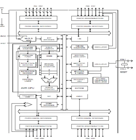
7) ATmega32
The ATmega32 is a low-power CMOS 8-bit microcontroller based on the AVR enhanced RISC architecture. By executing powerful instructions in a single clock cycle, the ATmega32 achieves throughputs approaching 1 MIPS per MHz allowing the system designer to optimize power consumption versus processing speed.
Block Diagram
Figure 5. Block Diagram Atmega32
Pin Descriptions
VCC Digital supply voltage. GND Ground.
8) TRANSFORMER
Transformer is a major class of coils having two or more windings usually wrapped around a common core made from laminated iron sheets. It has two cols named primary and secondary. If the current flowing through primary is fluctuating, then a current will be inducted into the secondary winding. A steady current will not be transferred from one coil to other coil.
Figure 6. Transformer
9) DIODE
The diode is a p-n junction device. Diode is the component used to control the flow of the current in any one direction. The diode widely works in forward bias.
Figure 7. Diode Symbol
When the current flows from the P to N direction. Then it is in forward bias. The Zener diode is used in reverse bias function i.e. N to P direction. Visually the identification of the diode`s terminal can be done by identifying he silver/black line. The silver/black line is the negative terminal (cathode) and the other terminal is the positive terminal (cathode).
APPLICATION
Diodes: Rectification, free-wheeling, etc Zener diode: Voltage control, regulator etc.
RESISTORS
A resistor is a two-terminal electronic component designed to oppose an electric current by producing a voltage drop between its terminals in proportion to the current, that is, in accordance with Ohm's law:
V = IR
Figure 8. Resistors
10) Potentiometers
A common element in electronic devices is a three-terminal resistor with a continuously adjustable tapping point controlled by rotation of a shaft or knob. These variable resistors are known as potentiometers when all three terminals are present, since they act as a continuously adjustable voltage divider. A common example is a volume control for a radio receiver.
11)Capacitors
A capacitor or condenser is a passive electronic component consisting of a pair of conductors separated by a dielectric. When a voltage potential difference exists between the conductors, an electric field is present in the dielectric. This field stores energy and produces a mechanical force between the plates. The effect is greatest between wide, flat, parallel, narrowly separated conductors.
Figure 9. Types of Capacitor
12) LED
LEDs are semiconductor devices. Like transistors, and other diodes, LEDs are made out of silicon. What makes an LED give off light are the small amounts of
chemical impurities that are added to the silicon, such as gallium, arsenide, indium, and nitride.
When current passes through the LED, it emits photons as a byproduct. Normal light bulbs produce light by heating a metal filament until it is white hot. LEDs produce photons directly and not via heat, they are far more efficient than incandescent bulbs.
Figure-10 (a) Typical LED Figure-10 (b) Circuit symbol
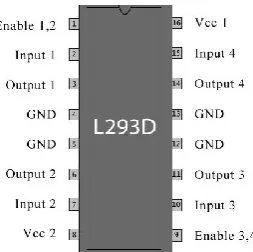
13) Motor Driving Circuit:
The DC gear motor is used in the robot. To build the motor drive circuit first we chose LM324 and L293D.But in the circuit we used L293D IC .It is a 16 pin chip called L293D. It can drive 2 DC motors. We connected the IC with arduino uno. Then we programmed it as per it is required. By the following figure the IC is narratively describe
Figure 11. Circuit Diagram
III. CONCLUSION
IV. REFERENCES
[1]. Aswath S, Chinmaya Krishna Tilak, Amal Suresh and GaneshaUdupa, "Human Gesture Recognition for Real Time Control of Humanoid Robot", International Journal of Advances in Mechanical and Automobile Engineering (IJAMAE), Vol-1, Issue 1, PP.96-100, (2014). [2]. Shruthi B. N, Shivraj, Sumathi S, "Hand Gesture
Based Direction Control of Robocar using Arduino Microcontroller", International Journal of Recent Technology & Engineering(IJRTE), Volume-3, Issue-3,PP.-32-35, July 2014.
[3]. Vicky Somkuwar, RoshanGabhane, Sandeepkakde, "Design and Implementation of Gesture Controlled Robot using Flex sensor and Accelerometer".
[4]. GauravGautam, AbhijeetAshish, Anil Kumar, Avdesh, "Wirelessly Hand Glove Operated Robot", International Journal of AdvancedResearch in Electronics and Communication Engineering (IJARECE), Volume-3, Issue-11,PP.-1546-1547, November 2014.
[5]. Harish Kumar Kaura, VipulHonrao, SayaliPatil, PravishShetty, "Gesture Controlled Robot using Image Processing", International Journal of AdvancedResearch in Artificial Intelligence (IJARECE), PP.-69-77, Vol-2, No.-5[2013]. [6]. http://www.eleinmec.com/datasheets/ds_holtek_
ht12d.pdf