CSEIT1846150 | Published – 08 May 2018 | May-June 2018 [ (4 ) 6 : 793-802 ]
National conference on Engineering Innovations and Solutions (NCEIS – 2018)
International Journal of Scientific Research in Computer Science, Engineering and Information Technology
© 2018 IJSRCSEIT | Volume 4 | Issue 6 | ISSN : 2456-3307
1
Solution for Effect of Zero Sequence Currents on Y-Y
Transformer Differential Protection
Goutham Pramath H1, Shaik Nadeem2 , Sunitha N S3, Narendra kumar k4 1 M.Tech student, AIT, Bangalore, Karnataka, India
2Application manager – ABB, Karnataka, India
3Asst.prof, AIT, Bangalore, Karnataka, India
4Sr. Test Engineer-ABB, Karnataka, India
ABSTRACT
In this paper, Transformer Differential protection mal-operations during external faults due to zero sequence current circulation on one side of the transformer is described with an example 132/33kV 60MVA Y-Y transformer. A simplest and modern solution is recommended with the comparison of conventional technology. Differential protection is a unit protection, which should not issue trip for external faults.
When a single phase fault occurred in a transmission line, a small part of zero sequence current feeding from remote end will take a path from one side of the transformer connected to this line. Generally this current is higher than minimum pick-up of Transformer Differential protection. Since there will be no reflected current on other side of the transformer corresponding to this fault current, transformer differential protection can issue trip when this zero sequence current is higher than pick-up value. This scenario is simulated in MiPower software by considering HV side of the transformer connected to the grid via a transmission line and LV side is connected to strong, weak and no source cases to observe zero sequence current flow in transformer. These results are verified with manual calculations also.
Generally zero sequence currents during external faults will cause mal operations of transformer differential protection for Yd and Dy type transformers. But this paper explains a different scenario with Y-Y transformers differential protection mal operation for eternal transmission line faults. Recently this problem is facing by many of the solar plant substations even with YN-yn transformers and generating plants. Hence a solution is prepared with numerical relay of ABB make RET670 and prepared solution is tested in the laboratory for the disturbance took place in a 132kV substation using Omicron injection unit. Conventional solution during electromechanical and static relays with interposing delta connected CT to filter zero sequence currents for external faults is also described in this paper.
I.
INTRODUCTION
Power system has evolved from many years and it is increasing day to day. There are many components orequipments in power system which are provided with proper protection such as Generators, Transformers, Reactors, Lines, Busbars and
transformers and the power transformer. Internal electrical faults are very serious and will cause immediate damage. Short circuits and earth faults in windings and terminals will normally be detected by the differential protection. Interturn faults are flashovers between conductors within the same physical winding. It is possible to detect interturn faults differential protection if sufficient number of turns is short-circuited. Interturn faults are the most difficult transformer winding fault to detect with electrical protections. A small interturn fault including just a few turns will result in an undetectable amount of current until it develops into an earth or phase fault. For this reason it is important that the differential protection has a high level of sensitivity and that it is possible to use a sensitive setting without causing unwanted operations during external faults. It is important that the faulty transformer be disconnected as fast as possible. As the differential protection is a unit protection it can be designed for fast tripping, thus providing selective disconnection of the faulty transformer. The differential protection should never operate on faults outside the protective zone.
II.
MALOPERATION OF TRANSFORMER
DIFFERNTIAL PROTECTION
A Transformer Differential protection compares the current flowing into the transformer with the current leaving the transformer [1]. A correct analysis of fault conditions by the differential protection must take into consideration changes due to the voltage, current and phase angle caused by the protected transformer. Traditional transformer differential protection functions required auxiliary transformers for correction of the phase shift and ratio. The numerical microprocessor based differential algorithm ass implemented in the IED compensates for both turn-ratio and the phase shift internally in the software. No auxiliary current transformer is necessary.
The differential current should theoretically be zero during normal or external faults if the turn-ratio and the phase shift are correctly compensated. However, there are several different phenomena other than internal fault that will cause unwanted and false differential currents. The main reason for unwanted differential current may be.
Mismatch due to varying tap changer position
Different characteristics, loads and operating conditions of the current transformers Zero sequence currents that only flow on one
side of the power transformer Normal magnetizing currents Magnetizing currents
Overexcitation magnetizing currents
A proper connection of the CTs or emulation of such a connection in a digital relay addresses the phase shift problem. A very complex problem is that of discriminating internal fault currents from the false differential currents caused by magnetizing inrush and the transformer Overexcitation.
1) INRUSH CURRENTS
Magnetizing inrush current in transformers comes about because of any sudden difference in the magnetizing voltage. Although typically considered because of energizing a transformer, the magnetizing inrush might be likewise caused by
•Event of an external fault,
• Voltage recuperation in the wake of clearing an external fault,
• Change of the character of a fault (for instance when a phase to-ground fault develops into a phase to- phase to-ground fault).
•Out-of-stage synchronizing of an associated generator.
and is in this way experienced by the differential off as a "false" differential current. The hand-off, be that as it may, must stay stable amid inrush conditions. Also, from the stance of the transformer life-time, stumbling out amid inrush conditions is an extremely unwanted circumstance (breaking a current of an unadulterated inductive nature produces high overvoltage that may risk the protection of a transformer and be a circuitous reason for an internal fault).
The main characteristics of inrush currents are followed by
Generally inrush currents contains dc offset, odd harmonics, and even harmonics
Regularly made out of unipolar or bipolar pulses, isolated by interims of low current values.
High values of unipolar inrush current pulses diminish gradually.
Time constant is regularly considerably more prominent than that of the exponentially decaying Dc offset of fault currents.
A second harmonic content begins with a low value and increases as the inrush current reduce.
2) OVER EXCITATION CONDITION
Over excitation of a transformer could cause unnecessary operation of transformer differential relays. This situation may occur in generating plants when a unit-connected generator is separated while exporting VARs [2]. The resulting sudden voltage rise impressed on the unit transformer windings from the loss of VAR load can cause a higher than nominal volts per hertz condition and, therefore, an Over excitation event. This could also occur in transmission systems where large reactive load is tripped from a transformer with the primary winding remaining energized.
When the primary winding of a transformer is overexcited and driven into saturation, more power appears to be flowing into the primary of the
transformer than is flowing out of the secondary. A differential relay, with its inputs supplied by properly selected CTs to accommodate ratio and phase shift, will perceive this as a current differential between the primary and secondary windings and, therefore, will operate. This would be an undesirable operation, as no internal fault would exist, with the
triples) may be effectively cancelled in transformer windings, then, the fifth harmonic can be used as a restraining or a blocking quantity in the differential relay in order to discriminate between the over-excitation and the faulty state.
3) CT SATURATION
The effect of CT saturation on transformer differential protection is double-edged. For external faults, the resulting false differential current may produce relay mis-operation. In some cases, the percentage restraint in the relay addresses this false differential current. For internal faults, the harmonics resulting from CT saturation could delay the operation of differential relays having harmonic restraint or blocking.
The main characteristics of CT saturation are the following.
1. CTs reproduce faithfully the primary current for a given time after fault inception. The time to CT saturation depends on several factors, but is typically one cycle or longer.
3.When the DC offset dies out, the CT has only AC saturation, characterized by the presence of odd harmonics in the secondary current.
Differential relays perform well for external faults, as long as the CTs reproduce the primary currents correctly. When one of the CTs saturates, or if both CTs saturate at different levels, false operating current appears in the differential relay and could cause relay maloperation. Some differential relays use the harmonics caused by CT saturation for added restraint and to avoid maloperation.
4) ZERO SEQUENCE CURRENTS
A Differential protection may operate undesirably due to external earth-faults in cases where the zero sequence current can flow on only one side of the power transformer, but not on the other side. This is the case when zero sequence current cannot be properly transformed to the other side of the power transformer. Power transformer connection groups of the Yd or Dy type cannot transform zero sequence current. If a delta winding of a power transformer is earthed via an earthing transformer inside the zone protected by the differential protection there will be an unwanted differential current in case of an external earth-fault. The same is true for an earthed star winding. Even if both the star and delta winding are earthed, the zero sequence current is usually limited by the earthing transformer on the delta side of the power transformer, which may result in differential current as well.
The above mentioned zero sequence current flow generally occur in Yd or Dy type transformers which cannot transform the zero sequence currents from one side to other side and causes the operation of transformer Differential relay for the faults external to the transformer protected zone. But in this paper, a special scenario is discussed where the zero sequence currents flow only on one side of the transformer in Yn-yn type transformer for SLG fault on the transmission line.
When a SLG fault occurred in a transmission line connected to transformer HV side, portion of the fault current fed from the remote end of the transmission line will take a path from transformer HV side. During this situation there will be no reflected current on LV side of the transformer. This current on HV side generally be higher than transformer Differential protection pick-up (0.2*In = 20% rated current) hence Differential protection will issue a trip.
Below simulations can give clear understanding of zero sequence current flow on only one side of the Yn-yn
transformer for the fault near to the transformer and far away from the transformer
1. SIMULATION OF ZERO SEQUENCE CURRENT IN A PRACTICAL NETWORK
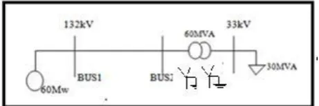
The single line diagram of the practical system with source of 60MW connected to the 132/33kV, 60MVA (YN-yn) grounded transformer through a 132kV transmission line of length 19km. The LV side of the transformer is connected to a lumped load of 30MVA as shown in fig1. Mipower simulation tool is used for the network construction.
Figure 1. Single line diagram
1) Case1. SLG Fault at bus 1(Far from the transformer)
Figure 2. SLD showing SLG fault at bus 1
A SLG fault at bus-1 is simulated using short circuit analysis with results of fault current is shown in Figure3.
Figure3. Simulation result for SLG fault at bus-1
Total fault current = 14.826kA
Fault current flow in transformer 132kV winding = 0.396kA 132kV side rated current at 60MVA = 262A Differential protection pick up = 20% of (Irated at 132kV side)
=52.5 A
Hence Differential protection goes to trip
Sequence network of the above simulation study is drawn and shown in Figure4. In this Figuretotal fault current is If and the fault current flowing through the transformer is If2 and balance current If1 is completed the path without the transformer.
Figure4. Sequence network for SLG fault at bus-1
Total fault current (If) and fault current via transformer (If2) calculations are shown below. These calculations are given in support of above simulation
3∗ ℎ
If = 1+ g2+ 0∗{ 0+ 0}…...(1)
+ 0+ 0 If = 0.0395- j14.8227
If = 14.822kA at an angle -89.8
Fault current fed from the transformer If2= If*{ + TL0+ TR0}
If2 = 0.3711kA at an angle 1.6982
2) Case2. SLG Fault at bus 2 (near to the transformer)
A SLG fault at bus 2 is simulated using the short circuit analysis as shown in Figure5.
Figure 5. SLG fault at bus 2
he fault current at bus 2 is calculated by considering the fault current feeding from the source and the fault current from the HV side of the transformer as shown in the Figure6.
simulation small amount of fault current completes the path through the transformer HV winding. The fault current for practical case is calculated from the sequence network diagram as shown in Figure6.
Figure 6. Simulation result for SLG fault at bus-2
Total fault current = 5.394kA
Fault current flow in transformer 132kV winding = 0.812kA 132kV side rated current at 60MVA = 262A Differential protection pick up = 20% of (Irated at 132kV side)=52.5 A
Hence Differential protection goes to trip
Sequence network of the above simulation study is drawn and shown in Figure4. In this Figuretotal fault current is If and the fault current flowing through the transformer is If2 and balance current If1 is completed the path without the transformer.
Figure 7. Sequence network for SLG fault at bus-1
Total fault current (If) and fault current via transformer (If2) calculations are shown below. These calculations are given in support of above simulation.
3∗ ℎ
If = 1+ 1+ 2+ 2+ 0+ 0 ( 0)……… (2)
0+ 0+ 0 If = 1.177-j5.269
If = 5.398kA at an angle -77.40
Fault current fed from the transformer
If2 = If * { +
} + TL0+ TR0
If2 = 0.7625kA at an angle -10.8089 3) Comparison table
The above cases can be summarized with a comparison table giving the information about the fault current by manual calculation and simulation result for practical case.
Table 1. comparison table of fault current contributions at Bus-1 & Bus-2
Manual Simulation CASE calculation Results
Total fault current IF =14.822kA IF =14.826kA at bus-1
Total fault current IF =5.398kA IF =5.394kA at bus-2
Fault current on
HV side of IF =371.1A IF =396.43A transformer(case-1)
Fault current on
From the above section it is proved by the simulation result and manual calculations that zero sequence current flow on HV side of the transformer only, which does not have reflected value on the LV side of transformer. This differential current seen by the relay is higher than then pickup value set and transformer differential protection issues trip signal for the fault external to the protected area.
III. ELIMINATION OF ZERO SEQUENCE
CURRENTS
To avoid unwanted trips for external earth-faults, the zero sequence currents should be subtracted on both side of the protected power transformer even for Y-Y grounded transformers. This will avoid mal operation of differential protection wherever the zero sequence currents can flow at external earth -faults. The zero sequence currents can be explicitly eliminated from the differential currents and common bias current calculation by special, dedicated parameter settings, which are available for every individual winding.
Elimination of the zero sequence component of current is necessary whenever.
1. The protected power transformer cannot transform the zero sequence currents to the other side.
2. The zero sequence currents can only flow on one side of the protected power transformer
In most cases, power transformers do not properly transform the zero sequence current to the other side. A typical example is a power transformer of the star-delta type, for example YNd1. Transformers of this transformer, but not on the other side. This results in false differential currents consisting exclusively of the zero sequence currents. If high enough, these
false differential currents can cause an unwanted disconnection of the healthy power transformer. They must therefore be subtracted from the fundamental frequency differential currents if an unwanted trip is to be avoided.
For delta windings this feature shall be enabled only if an earthing transformer exists within the differential zone on the delta side of the protected power transformer. Removing the zero sequence current from the differential currents decreases to some extent the sensitivity of the differential protection for internal earth -faults. In order to counteract this effect to some degree, the zero sequence current is subtracted not only from the three fundamental frequency differential currents, but from the bias current as well. It shall be noted that if the zero-sequence currents are subtracted from the separate contributions to the total differential current, then the zero-sequence component is automatically eliminated from the bias current as well.
1. Algorithm to eliminate zero sequence currents in numerical relays
The fundamental frequency differential current is a vectorial sum (sum of fundamental frequency phasors) of the individual phase currents from the different sides of the protected power transformer.
Before any differential current can be calculated, the power transformer phase shift, and its transformation ratio, must be accounted for. Conversion of all currents to a common reference is performed in two steps.
all current phasors are phase-shifted to (referred to) the phase-reference side, (whenever possible the first winding with star connection)
Where.
1.is the resulting Differential Currents
2.is the current contribution from the W1 side 3.is the current contribution from the W2 side Values of the matrix A, B and C coefficients depend on.
1.The Power transformer winding connection type, such as star (Y/y) or delta (D/d)
2. The Transformer vector group such as Yd1, Dy11, YNautod5, Yy0d5 and so on, which introduce phase displacement between individual windings currents in multiples of 30°.
3.The Settings for elimination of zero sequence currents for the individual windings.
The fundamental frequency differential currents are in general composed of currents of all sequences, that is, the positive-, the negative-, and the zero-sequence currents. If the zero-sequence currents are eliminated, then the differential currents can consist only of the positive-, and the negative-sequence currents. When the zero-sequence current is subtracted on one side of the power transformer, then it is subtracted from each individual phase current.
The site DR is transplayed in the lab as inputs to the omicron kit to the relay. The results of testing without and with solution are shown in below Figs 9, 10.
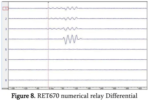
Figure 8. RET670 numerical relay Differential protection settings
To confirm the trip form transformer differential protection numerical relay, a Disturbance recorder file is taken form 132/33kV substation exactly matching to above simulation studies. The DR file is transplayed in laboratory using ABB RET670 (Transformer Differential relay) Numerical relay and omicron injection kit which is used to inject the voltage and current values to the relay for testing. In present case the HV and LV current values for injection are taken from a real disturbance at 132/33kV substation where the transformer Differential protection tripped. When the DR file received from the site is transplayed in laboratory, omicron injects the HV and LV current values corresponding to Disturbance took place in substation. Hence the behavior of numerical relay RET670 will be same as that of relay available at site. The recorded disturbance contained flow of zero sequence currents in HV side of the transformer which tripped differential relay for the fault on the transmission line which was external to the protected zone.
In PCM software settings, the differential relay with zero sequence current elimination is activated as shown in Fig 8.
Figure 9(b). Binary signals triggered for the disturbance at site (After solution)
From the figure 8(a) & 8(b), it is observed that the zero sequence currents flows on HV side of the transformer and no reflected current flows on LV side of the transformer. Hence differential relay trips as it sees a differential current higher than pick-up value of relay.
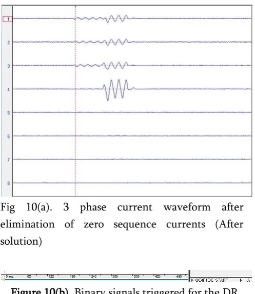
Fig 10(a). 3 phase current waveform after elimination of zero sequence currents (After solution)
Figure 10(b). Binary signals triggered for the DR Transplayed at lab (After solution)
Referring to the figs-9(a) & 9(b), it can be verified that the zero sequence currents are eliminated from the fundamental frequency differential currents of 3 phases and the differential protection relay doesn’t trip for the external faults outside the protected zone due to the zero sequence current contribution. Solution for conventional electromechanical/static
relays to eliminate zero sequence currents will be achieved by using Interposing CT’s
Figure 11. Interposing CT
In the above Figure 11, CT’s are connected in delta, otherwise interposing CT’s are used which will be connected in delta to remove zero sequence current.
IV.
CONCLUSION
Transformer Differential protection is a unit protection which should operate for the faults between the HV side CT and LV side CT used for Differential protection. One of the frequent reason of transformer Differential undesired operation is elimination of zero sequence currents on star side of the transformer for Yd and Dy type of transformers as per the recommendations from most of the relay manufacturers but in this paper a different concept is taken with Yn-yn transformer where zero sequence currents can be easily transformed from one side of the transformer to the other side. Simulations and manual calculations are carried out for an external fault to the transformer and shown that there is a possibility of zero sequence currents on only one side of the transformer, which can be resulted in Differential protection trip.
Disturbance Recorder file, RET670 (ABB transformer protection numerical relay and omicron kit) to confirm the satisfactory of solution suggested in this paper.
V.
REFERENCES
[1] CIGRE-Modern techniques for protecting, controlling and monitoring power transformers-463, working group-B5.05-june 2011
[2] IEEE guide for the protection of network transformers, IEEE Std c37.108_2007
[3] Preventing Transformer mis-operations for external faults, Rene Aguilar, Megger, Odessa, Texas [email protected]
[4] Power Transformer Protection Improvements With Numerical Relays, CIGRE Study Committee B5 Colloquium Calgary, Canada September 14 16, 2005