Article
1
Open Source Waste Plastic Granulator
2
Arvind Ravindran 1, Sean Scsavnicki 1 , Walker Nelson 1 , Peter Gorecki 1 , Shane Oberloier 2,
3
Theresa K. Meyer 3, Andrew R. Barnard 1 , Joshua M. Pearce 2,3,4,*
4
1 Department of Mechanical Engineering–Engineering Mechanics, Michigan Technological University,
5
Houghton, MI, 49931; [email protected]@[email protected]@mtu.edu
6
7
2 Department of Electrical & Computer Engineering, Michigan Technological University, Houghton, MI,
8
49931; [email protected]@mtu.edu
9
3 Department of Material Science & Engineering, Michigan Technological University, Houghton, MI, 49931;
10
[email protected]@mtu.edu
11
4 Department of Electronics and Nanoengineering, School of Electrical Engineering, Aalto University, Espoo,
12
Finland, FI-00076; [email protected]
13
14
* Correspondence: [email protected]; Tel.: +01-906-487-1466
15
16
Abstract: In order to accelerate deployment of distributed recycling by providing low-cost feed
17
stocks of granulated post-consumer waste plastic, this study analyzes an open source waste plastic
18
granulator system. It is designed, built and tested for its ability to convert post-consumer waste, 3-D
19
printed products and waste into polymer feedstock for recyclebots of fused particle/granule printers.
20
The technical specifications of the device are quantified in terms of power consumption (380 to 404W
21
for PET and PLA, respectively) and particle size distribution. The open source device can be
22
fabricated for less than USD$2000 in materials. The experimentally-measured power use is only a
23
minor contribution to the overall embodied energy of distributed recycling of waste plastic. The
24
resultant plastic particle size distributions were found to be appropriate for use in both recyclebots
25
and direct material extrusion 3-D printers. Simple retrofits are shown to reduce sound levels during
26
operation by 4dB-5dB for the vacuum. These results indicate that the open source waste plastic
27
granulator is an appropriate technology for community, library, makespace, fab lab or small
28
business-based distributed recycling.
29
Keywords: 3-D printing; additive manufacturing; distributed manufacturing; distributed recycling;
30
granulator; shredder; open hardware; fab lab; open-source; polymers; recycling; waste plastic;
31
extruder; upcycle; circular economy
32
33
1. Introduction
34
The open-source release of the self-replicating rapid prototyper (RepRap) 3-D printer [1-3]
35
greatly expanded access to additive manufacturing (AM) because of several orders of magnitude
36
reduction in costs [4]. As open-source RepRap 3-D printers spawned hundreds of clones, fused
37
filament fabrication (FFF) enabled a shift in the trend from centralized to consumer (or prosumer)
38
distributed manufacturing [4-8]. Consumers now use RepRaps or pre-built desktop 3-D printers to
39
manufacture all manner of products from toys to household items less expensively than purchasing
40
them from conventional brick and mortar or online retailers [9-11]. The peer-reviewed business
41
literature now recognizes this potential shift in manufacturing [12-14], which is brought on not only
42
by the open source sharing of 3-D printer designs, but now more importantly because of millions of
43
freely shared digital designs of other products that are 3-D printable [9]. Any level of consumer from
44
scientific research funders to arthritis patients [15] can earn a high return on investment (ROI) [16]
45
for distributed manufacturing with commercial polymer 3-D printing filament based on downloaded
46
substitution values [17]. However, commercial 3-D printing filament is still sold for roughly an order
47
of magnitude more than the cost of the raw materials of virgin plastic pellets. This has reduced
48
adoption of AM at the prosumer level [18]. There are two methods to overcome this artificial cost
49
barrier for wider spread distributed manufacturing: 1) use distributed recycling to make filament and
50
2) skip the entire process of fusing filament into a 3-D printed object by printing directly from
51
polymer granules, shards or particles.
52
3-D printing filament can be manufactured economically using distributed means with an open
53
source waste plastic extruder (often called a recyclebot) [19]). Recycling is a well-known
54
environmental benefit and performing distributed recycling of plastic waste into filament decreases
55
the embodied energy of filament by 90% compared to traditional centralized filament manufacturing
56
using fossil fuels as inputs [20-22]. Using distributed recycling fits into the circular economy
57
paradigm [23-26] as it eliminates most embodied energy and pollution from transportation between
58
processing steps. Many open source commercial and non-commercial recyclebots have been
59
developed [27] including a 3-D printable version [28]. Many research groups and companies have
60
demonstrated that pre-consumer and post-consumer waste polymers can be recycled into 3-D
61
printing filaments, including:
62
• polylactic acid (PLA) [28-32]
63
• acrylonitrile butadiene styrene (ABS) [24,33-36],
64
• high-density polyethylene (HDPE) [19,37,38],
65
• polypropylene (PP) [38],
66
• polystyrene (PS) [38],
67
• polyethylene terephthalate (PET) [39],
68
• linear low density polyethylene (LLDPE) and low density polyethylene (LDPE) [40],
69
• elastomers [8],
70
In addition, filaments can be made from polymer composites using carbon reinforced plastic [41] and
71
various types of waste wood [42,43]. Unfortunately, each melt-solidification degrades the mechanical
72
properties of the resultant 3-D print [44,45] recycling is limited to about five cycles [46,47] without
73
use some means of reinforcement or blending with virgin materials. The potential for such distributed
74
recycling could be either completely distributed (where the consumer recycles their own plastic in
75
their home or business) or part of a local closed-loop supply chain [48].
76
The second method, however, eliminates the need for filament entirely as 3-D printers have been
77
developed that can print directly from particles, pellets, flakes, regrind, or shreds of recycled plastic.
78
These fused particle fabrication (FPF) or fused granular fabrication (FGF) 3-D printers and are
79
becoming established in the academic [49-54], maker [55-57], and commercial venues (e.g. GigabotX,
80
PartDaddy, Cheetah Pro, David, Erecto-Struder, etc.). FPF/FGF printing is possible with recycled
81
materials [58-60] as is using FGF printing of molds for distributed injection molding of larger replicate
82
products [60].
83
Both the widespread deployment of distributed recycling with recyclebots and FPF/FGF are
84
being restricted because of the lack of accessibility of low-cost pelletizers and choppers to turn
post-85
consumer plastic products into polymer feedstock. In general, these are large industrial machines not
86
conducive for makerspaces, fab labs, research or consumer use because of their high throughputs,
87
noise and capital costs. In order to provide a low-cost tool for making polymer feedstock from
post-88
consumer waste this study follows the open-source hardware design paradigm [61,62], which has
89
proven so successful for 3-D printing in general. An open source waste plastic granulator system is
90
designed, built and tested for its ability to convert post-consumer waste, D printed products and
3-91
D printer waste into polymer feedstock for recyclebots of FGF/FPF printers. Then the technical
92
specifications of the device are quantified in terms of power consumption and particle size of the
93
output. In order for the device to operate in a fab lab (or similar environment) a noise reduction
94
system is added and analyzed. The results are presented and discussed.
95
2. Design Concept
The design of the open source waste plastic granulator system is divided into four separate
sub-97
systems, each responsible for parts of the machine that serve a specific function:
98
1. Power Transmission: This system encompasses all machine parts needed to convert the electrical
99
energy being input to the system into mechanical energy, as well as transmit that mechanical
100
energy to the plastic cutting/granulation system.
101
2. Plastic Cutting/Granulation: This system is the one that directly interacts with the plastic in order
102
to cut it into small chunks. It is responsible for cutting plastic as well as ejecting granules after
103
they have reached a uniform size.
104
3. Material Guidance/Structural: This system involves any parts that keep the plastic feedstock
105
inside of the proper cutting area during operation or guide the feedstock during its journey. It
106
includes the hopper chute, the hopper lip, the granulation chamber lip, any mechanism used to
107
hold the hopper to the granulation chamber, and the upper surfaces of the granulation chamber.
108
4. Electrical: This system encompasses all of the components required to convert electrical energy
109
from mains power into rotational energy, as well as any other electrical peripherals present on
110
the machine. This includes the electrical box, safety switches, circuit board, motor, and a
111
microcontroller.
112
Together, these systems operate all with the end goal of transforming plastic recyclables into
113
usable 3-D printing feedstock in the form of granules (or particles). The main concepts and parts in
114
each sub-system will be described but the full open hardware details including the bill of materials
115
(BOM), drawings for custom parts, CAD files, build instructions and design reports of previous
116
versions are housed at the Open Science Framework [63].
117
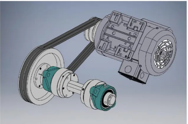
2.1. Power Transmission System
118
The power transmission system transfers rotational mechanical energy from the motor spindle
119
to the cutting rotor shaft. As a first step towards designing this subsystem of the machine the design
120
team made the decision that a one-phase AC motor would be used to supply mechanical power to
121
the machine. This method of mechanical power delivery is the most reliable and easiest way for an
122
individual to drive a machine from their home circuitry. Pulleys and belts are used to convey power
123
to the cutting rotor; belts are not only inexpensive when compared to a gearbox, but are also more
124
user friendly since they are easy to install, maintain and adjust once assembled. An isolated view of
125
the 3-D model for the power transmission subsystem and all of its components can be seen in Figure
126
1.
127
128
Figure 1: Power transmission system design of the open source waste plastic granulator.
129
As seen in the Figure 1, the parts of the power transmission system are as follows: AC Motor,
130
pulleys, belts, flange-mount bearings, rotor shaft, quick-disconnect (QD) bushings, and weld-on hubs
(plus mounting hardware). The motor selected to drive the granulator is a 1.5 HP motor with a
132
spindle speed of ~1800 RPM. On a previous version of the open source waste plastic granulator, the
133
optimal rotor speed for cutting was found to be around 750 RPM [62]; this speed was also used for
134
this design as well, leading to a set ratio of pulley diameters of about 1:2.4. A 3.95” (100.33 mm)
135
diameter pulley was chosen to connect to the motor spindle using a quick-disconnect style bushing.
136
An 8.75” (222.25 mm) diameter pulley was used to attach to the cutting rotor shaft, also with a
quick-137
disconnect bushing. Both pulleys have two channels for v-belts to ensure there is no slippage during
138
operation. In order to keep the cutting rotor shaft spinning about its major axis two large
flange-139
mount bearings were used. In order to connect the shaft to the cutting rotor, QD bushings were used
140
in conjunction with weld-on hubs to clamp to the shaft. These components were then bolted to the
141
cutting rotor so that the blades would spin with the shaft (see Figure 2).
142
2.2. Plastic Cutting System
143
The plastic cutting subsystem is, out of all of the subsystems, the most directly related to the
144
overall function of the machine as it is responsible for transforming plastic waste/recyclables into
145
granules of a specific size. In order to do this, the design team picked out many different forms that
146
would satisfy the subsystem’s purpose, and compared them using a decision matrix (details of which
147
are found in the OSF database [62]). From the decision matrix, the best option was found to be the fly
148
knife design, consisting of two large rotating blades (fly knives) that pass close to a fixed blade during
149
operation (Figure 2). Shear force on the plastic between the blades is the main cutting method.
150
151
Figure 2: Plastic cutting system design of the open source waste plastic granulator.
152
The plastic cutting system, consists of four separate components (plus mounting hardware).
153
Two blade arms will connect to the cutting rotor shaft (shown in Figure 2) and will spin with the
154
shaft. Connected to either end of each blade arm in the configuration shown below are two fly knives,
155
which will contact the plastic within the cutting chamber and shear through it. To help with the
156
cutting of the plastic granules, there are two more pieces in this system that both interact with the
157
rotating fly knives, the granulation screen and the bed blade. As the fly knives rotate in the
158
granulation chamber they will pass very close to the fixed bed blade on the right side of Figure 2.
159
This is where the large pieces entering the cutting chamber will be sheared for the first time. In
160
our design, all stress-bearing components related to this large cutting force were designed to be able
161
to cut ⅞” (22.2 mm) cubes of nylon mill stock. Once large pieces have been cut for the first time by
162
the bed blade, they will accumulate on the surface of the granulation screen. The clearance between
163
the tip of the fly knives during rotation and the inside of the screen in ~⅛” (3 mm), which means that
164
any larger granules will get pinched between the screen and the blade and be sheared to a smaller
165
size. Once the granules are smaller than ~¼” (6 mm) in all dimensions they are pulled through the
166
holes located in the granulation screen and into a collection chamber by a vacuum. In order to make
the blade arms rotate, as described in Section 2.1, weld-on hubs attached to the shaft were bolted onto
168
the blade arms.
169
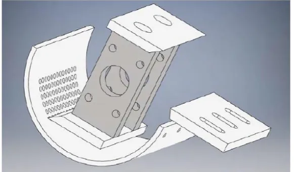
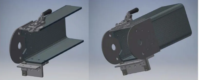
2.3. Material Guidance
170
The material guidance system is responsible for containing the waste plastic both before and
171
after the cutting operation. In addition to guiding materials, this system also serves as the structure
172
upon which all other subsystems are constructed. The feedstock is guided using a sloped tube as
173
shown in Figure 3.
174
175
Figure 3 Material guidance system (cut section and completed) for the open source waste plastic granulator.
176
Overall, the main component used for material guidance is a large steel square tube that not only
177
provides a smooth, enclosed surface for the waste plastic to slide on while it is on its way to be cut,
178
but also a very strong and rigid structure that can be built upon. Attached to this large (8” (203 mm)
179
width) square tube are several other components that support the plastic cutting and power
180
transmission systems. The two large rounded plates attached to the vertical faces of the tube are what
181
hold the bearings from the power transmission system in place. The angle iron on the bottom part of
182
the tube serves two purposes. The larger piece holds the fixed bed blade in place during operation,
183
as well as clamping to the second piece of angle iron shown, which secures the granulation screen in
184
place for cutting. The materials on the top of the tube are all responsible for holding the opposite side
185
of the granulation screen in place and allows the user to disconnect the granulation screen quickly
186
from one side. This system also includes a secondary tube acting as a hopper for funnelling material
187
directly from the user’s hand into the machine as well as a server rack cart that is used to house the
188
main cutting mechanism, however, these components are not shown above for clarity.
189
2.4. Electrical
190
The electrical system in the machine serves three purposes, powering the motor, powering the
191
granule extraction vacuum, and monitoring the power consumption of the machine. These functions
192
are accomplished simply since both the vacuum and the motor require no more than a simple on/off
193
control scheme. Both the vacuum and the motor are connected directly to 120VAC mains power and
194
use simple switches to control them. In addition, an emergency-stop switch is included in the
195
circuitry to cut power to the whole machine if necessary. The final accessory included in the electronic
196
circuit for this machine is a multimeter that provides a digital readout with information on the power
197
consumption of the machine. All of the components in the electrical system were designed to operate
198
using less than 15 Amps during steady-state conditions so that the machine could be run off of a
199
standard in-home wall outlet. A circuit diagram for the electrical system is included in Figure 4.
201
Figure 4: Circuit Diagram for electrical control system of the open source waste plastic granulator.
202
2.5. Peripheral Parts Assembly
203
Together, the four systems described in Section 2.1-2.4 work together to achieve the overall
204
objective of the design of the open source waste plastic granulator. Other than getting the material
205
from place to place, all of the actual manipulation of the plastic to transform it from stock material
206
into feedstock occurs due to the cutting and power transmission systems. An overall view of the
207
machine’s core systems are shown in Figure 5.
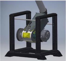
208
209
Figure 5: Overall design setup of the open source waste plastic granulator.
Figure 5 shows the assembly of the three mechanical design systems, including all of the parts
211
explained earlier as well some 3-D printed parts and several parts not shown before. As can be seen
212
in the above picture the server rack cart that was mentioned in the material guidance system is
213
housing the main systems of the granulator. It holds the machine components so that the major axis
214
of the large square tube is angled to allow plastic pieces to slide into the cutting mechanism. To
215
accomplish this, several standard size ½” (12.7 mm)) steel pipes are attached to the server rack using
216
u-bolts. The pipe in the rear (as shown in Figure 5) is attached directly to the bottom of the steel tube
217
using pipe straps, while the pipe in the front is attached via nylon strapping to the eye-bolts shown
218
on the top of the steel tube in the above figure. This is done to allow the builder of the machine to
219
easily add a vibration-dampening spring at the front attachment point to mitigate any rotational
220
imbalance that may be present in the machine. The hopper consists of the large tube sticking out of
221
the top of the server rack as well as a plate that allows it to attach to the back of the square steel
222
tube/main machine body. This allows users to safely place materials into the machine for cutting. The
223
bend that materials will have to pass through in order to get from the machine’s opening to the
224
cutting mechanism ensures that a user cannot accidentally place their hands/arms inside the machine
225
while it is cutting as well as stops granules from flying out of the machine during operation. To
226
highlight the interaction between all three main mechanical systems a cutaway view showing the
227
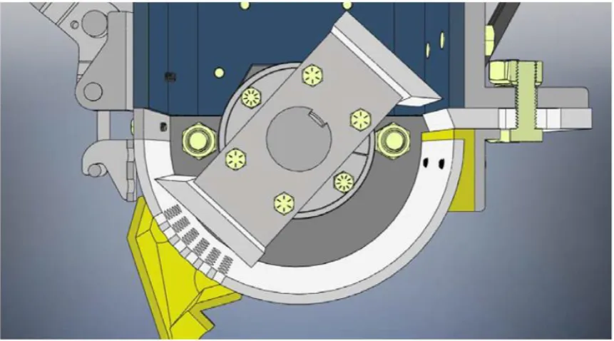
assembled granulation chamber in Figure 6.
228
229
230
Figure 6: Cutaway of mechanical systems in the open source waste plastic granulator.
231
2.4 Cutting Force Design Analysis
232
The cutting operation that takes place during the operation of the granulator is unpredictable so
233
a simulation was run of the cutting forces that occur during the operation of the granulator [62]. These
234
forces are important because they allow for the calculation of the stresses that occur inside the key
235
stress-bearing elements of the design. The method and findings are in the OSF database [62].
236
The stress levels inside the blade arm as well as the fly knife bolts are well below the acceptable
237
level for steel materials. In order to achieve this, it was determined that the blade arms must be made
238
out of ¾ ” (19 mm) x 2.5” (63.5 mm) steel flat stock, and that the bolts must be ⅜ ” - 16 UNC ( 9.525
239
mm) grade 8 hex cap screws. Previous simulations found that a 1/2” (12.7 mm) thick piece of angle
240
iron with side lengths of 3” (76.2 mm) would be suitably strong for this piece. ¼ ” (6.35 mm) - 20 UNC
241
bolts were selected despite being over engineered because they proved inexpensive for this
242
application. After iterating the simulation to find the optimal size for the bed blade mounting bolts,
243
both locations were considered and ½ ” (912.7 mm) -12 UNC grade 8 hex cap bolts were chosen.
Standard fatigue analysis [64] was performed and it was found that the Grade 9 bolts responsible for
245
attaching the fly knife blades to the blade arms are predicted to fail due to fatigue before infinite life.
246
That being said however, the analysis done assumes that a ¾ ” (19 mm) nylon block will enter the
247
machine once every time one knife rotates, which, for normal operation is very unlikely. For normal
248
use the stresses present will never reach the values used for analysis. However, users planning on
249
using this machine for nylon recycling should replace these bolts every month in order to avoid
250
failure due to fatigue. The maximum torque acting on the cutting rotor during operation is slightly
251
less than 1500 N-m, or about 13000 in-lbs. In order to attach the cutting rotor to the shaft two SK type
252
QD bushings were chosen, since each bushing can support a torque of 7000 in-lbs. Together, these
253
two bushings can support a maximum torque of 14000 in-lbs, a torque which should never be
254
exceeded during the normal operation of the machine. In conclusion, the design simulation indicated
255
that the technology as designed would be able to cut a maximum thickness of nylon stock of 3/4”
256
(19 mm), i.e. a cube measuring 3/4” (19 mm) on each side is the largest piece of plastic stock that
257
should be inserted into the machine.
258
3. Material and methods
259
3.1 Technical specifications: Power consumption and particle size
260
The power consumption operating the granulator as measured with an open-source printed
261
circuit board and Arduino Nano attached to the power supply to measure the power output of the
262
while it was processing different materials. During each of the power recording sessions,
263
thermoplastic was inserted at a rate the granulator could handle. This rate is not measured, as it
264
highly depends on the geometry and density of the inserted plastic.
265
266
The AC power measurement board collects data from both input legs of the 220 VAC power
267
input to the control electronics. Each leg’s corresponding voltage is measured by direct connection,
268
and current is measured using 100A non-invasive current transformers. Each leg’s measurements are
269
hooked into a channel of the board where the measurements are made using a dedicated Analog
270
Devices ADE7757 energy metering integrated circuit (IC). The IC meets the IEC61036 accuracy
271
requirements for power measurements. The ADE7757 transmits the wattage signal through its CF
272
pin, and is captured by the on-board Arduino Nano. The values are operated on by a linear calibration,
273
and then written to a microSD card, with time stamps generated by the on-board real time clock.
274
The size characteristics of the particles for the resultant granulated material were quantified
275
using digital imaging and the open source Fiji/ImageJ using techniques discussed previously [60].
276
3.2. Noise reduction
277
Sound pressure levels were measured using a free field array microphone positioned in front of
278
the vacuum inlet of the machine. The measurements were logged using a National Instruments
279
compact DAQ data acquisition system in conjunction with custom LabVIEW software. Multiple
280
positions were considered before finalizing on the position in Figure 7 due to repeatability and high
281
signal-to-noise ratio. All trials were performed using this microphone position Sources of sound in
282
the machine includes the shear cutting mechanism in the granulator and the shop vacuum. Although
283
the microphone location was not in the operator ear position, it was appropriately placed for
284
before/after insertion loss measurements.
286
Figure 7: Sound measurement test setup depicting the microphone in one of the test locations
287
Tests were performed to find the sound pressure levels of the open source waste plastic
288
granulator system including the auxiliary devices such as the vacuum pump and the individual
289
contributions as well. It was determined that the vacuum pump was the loudest source with a distinct
290
peak in the 250 Hz one third octave band. Panel gaps in the enclosure for the granulator provides
291
leakage paths for the sound and hence it was decided to seal these gaps appropriately. The inner
292
lining of the walls were packed with open-celled foam to increase sound absorption and transmission
293
loss as shown in Figure 8.
294
295
296
Figure 8: Granulator panel gaps filled with sound proofing material
297
Using the initial acoustic measurements, an expansion chamber was designed (Figure 9) that
298
could be attached to the 5-gallon bucket shop vacuum, and a 3-D model was produced to utilize PVC
299
and a 3-D printable components to reduce noise from the operation of the device. As 250Hz was the
300
chosen frequency one third octave band for attenuation, the double tuned expansion chamber design
301
was chosen as it provides good transmission loss around the frequency of interest while having good
302
attenuation around the octave bands as well [65]. However, the muffler aids in higher frequency
303
attenuation and by lining the inner walls of the muffler with fiberglass foam.
305
Figure 9: Comparison between CAD of chamber and finished expansion chamber.
306
4. Results
307
4.1 Technical specifications for particle size and energy use
308
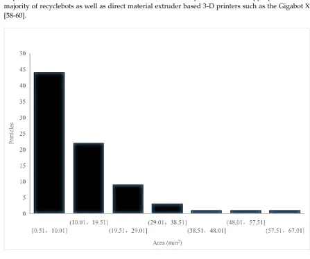
Figure 10 shows the resultant particles and particle size distribution, where it is clear that the majority
309
of particles are fines with total areas under 10 mm2. These particle sizes are appropriate for the
310
majority of recyclebots as well as direct material extruder based 3-D printers such as the Gigabot X
311
[58-60].
312
313
Figure 10. Resultant particle size distribution in mm2 after shredding in the open source granulator.
314
This power draw of the open source waste plastic granulator was processed and its results appear
315
below in a Table 1. The average power varied depending on the type of plastic and would be expected
316
to change based on the type of feedstock (e.g. large solid blocks vs flakes).
Table 1: Power consumption details
319
PLA
(Polylactic acid)
PET
(Polyethylene terephthalate)
Average power 403.6 W 383.9 W
320
4.2 Noise reduction results
321
The noise reduction modifications to the granulator were verified with sound level measurements
322
and are as shown in Figure 11. Compared to the earlier design, a 4dB overall reduction in sound
323
levels was achieved with attenuation at the 250Hz one third octave band particularly. As the focus of
324
the noise reduction was concentrated towards the vacuum, 5 dB reduction was achieved here.
325
326
Figure 11: Results of the sound reduction redesign showing a bar plot of 1/3 octave noise measurements.
327
5. Discussion
328
5.1 Technical specifications for particle size, through put, and energy use
329
The particle sizes demonstrated in Figure 18 are small enough to use in a wide array of recyclebots
330
(both commerical and homemade) as well as for direct printing via FPF/FGF as demonstrated in
[58-331
60].
332
The volumes that the device can process are appropriate for small businesses [13], community
333
centers, libraries, makespaces, and fab labs [59,66] that could potentially become community
334
distributed recycling centers. There are challenges with this approach throughout the world. So
335
although, libraries in Finland for example routinely offer their patrons free 3-D printing services,
336
many countries do not. In addition, the actual reycling process can be challenging due to lack of
337
appropriate information in specific countries. For example, China has a sophisticated recycling
338
symbol system [67] that covers a wide range of waste plastics, the U.S. grous most of its polymers
339
together in only 1 of 7 categories (7- “other”) [68]. In order to have low-cost distributed recycling
waste plastics need to be appropriately labeled. The open source 3-D printer community has already
341
devised a voluntary recycling code based on China’s comprehensive system [68]. To have a more
342
widespread impact and reach a cradle-to-cradle material cycle [69] regulations that demand that
343
manufacturers identify the materials in their products appears necessary [70].
344
The power draw for the open source waste plastic granulator is relatively mild, drawing as much
345
power as 3-4 conventional incandescent light bulbs. Coupling this low power use to the rapid
346
throughput of the technology results in a relatively low embodied energy of electricity for grinding
347
plastic with this machine. This is close to values that have been reported for commercial devices used
348
in previous studies of distributed recycling using additive manufacturing [20,21].
349
5.2 Noise reduction
350
Sealing the exhaust port of the suction vacuum with the muffler did reduce the noise levels
351
experienced, which make the system more amenable to non-production facility based applications
352
like mixed-use fab labs. As stated in the results, a 4 dB overall reduction from the granulator and the
353
suction vacuum combined was obtained and hence the muffler served the intended purpose.
354
However, efforts to control granulator noise were not as successful and this was possibly due to
355
existing panel gaps in the enclosure. They were not sealed off due to need for ease of access. Future
356
work is needed to explore other methods of sound reduction.
357
358
5.3 Future work
359
This technology is an open source technology built on prior designs [71] and will continue to evolve
360
in the traditional open source fashion. There are thus several areas of future work to improve on the
361
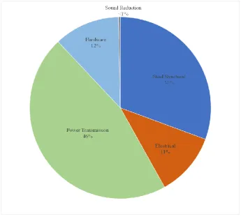
design of the open source waste plastic granulator. First, the cost of the materials for the device is
362
US$1,943.11, which limits its accessibility throughout many applications. The breakdown in the cost
363
of the materials can be seen in Figure 12.
364
365
Figure 12. Cost breakdown of the bill of materials for the open source granulator.
To further drive down costs, additional components should be redesigned to use digital
367
manufacturing technologies, the mass of parts should be minimized to maintain the necessary
368
mechanical integrity (which is most easily done in the reduction of structural steel that makes up
369
nearly a third of the cost), and the volume footprint of the device should be reduced. These costs were
370
for retail purchased materials and would be expected to drop significantly if an open hardware
371
company built the devices at even modest scale.
372
373
6. Conclusions
374
This study successfully demonstrate the designs, build and testing of an open source waste plastic
375
granulator for its ability to convert post-consumer waste, 3-D printed products and 3-D printer waste
376
into polymer feedstock for recyclebots of fused particle/granule printers. The device can be built from
377
open source plans using materials that cost less than US$2000. The device has a power consumption
378
(380 to 404W for PET and PLA, the most common post-consumer plastic waste and most popular
3-379
D printer plastic, respectively). With this device, granules can be produced with a particle size
380
distribution consistent with distributed recycling and manufacturing using open source recyclebots
381
and 3-D printers. Simple retrofits for the open source waste plastic granulator are shown to reduce
382
sound levels during operation by 4dB and 5dB for the vacuum. It can be concluded that the open
383
source waste plastic granulator is an appropriate technology for community, library, makespace, fab
384
lab or small business-based distributed recycling
385
Author Contributions: Conceptualization, Joshua M. Pearce; Data curation, Arvind Ravindran, Sean Scsavnicki,
386
Walker Nelson , Peter Gorecki , Shane Oberloier and Theresa K. Meyer ; Formal analysis, Arvind Ravindran,
387
Walker Nelson , Peter Gorecki , Shane Oberloier , Theresa K. Meyer , Andrew R. Barnard and Joshua M. Pearce;
388
Funding acquisition, Joshua M. Pearce; Investigation, Arvind Ravindran, Sean Scsavnicki , Walker Nelson , Peter
389
Gorecki , Shane Oberloier and Theresa K. Meyer ; Methodology, Arvind Ravindran, Walker Nelson , Peter
390
Gorecki , Shane Oberloier and Theresa K. Meyer ; Resources, Andrew R. Barnard and Joshua M. Pearce;
391
Supervision, Joshua M. Pearce; Validation, Arvind Ravindran, Sean Scsavnicki , Walker Nelson , Peter Gorecki ,
392
Shane Oberloier and Theresa K. Meyer ; Visualization, Arvind Ravindran, Walker Nelson and Peter Gorecki ;
393
Writing – original draft, Arvind Ravindran and Joshua M. Pearce; Writing – review & editing, Arvind Ravindran,
394
Sean Scsavnicki , Walker Nelson , Peter Gorecki , Shane Oberloier , Theresa K. Meyer , Andrew R. Barnard and
395
Joshua M. Pearce.
396
Funding: This research was funded by the Witte Endowment.
397
Acknowledgments: The authors would like to acknowledge technical support from Paul Fraley.
398
Conflicts of Interest: The authors declare no conflict of interest. The funders had no role in the design of the
399
study; in the collection, analyses, or interpretation of data; in the writing of the manuscript, or in the decision to
400
publish the results.
401
References
402
1. Sells, E.; Bailard, S.; Smith, Z.; Bowyer, A.; Olliver, V. RepRap: The Replicating Rapid
Prototyper-403
Maximizing Customizability by Breeding the Means of Production. Proceedings in the World Conference
404
on Mass Customization and Personalization, 2010. Cambridge, MA, USA, 7-10 October 2007.
405
2. Jones, R.; Haufe, P.; Sells, E.; Iravani, P.; Olliver, V.; Palmer, C.; Bowyer, A. RepRap-the Replicating Rapid
406
Prototyper. Robotica 2011, 29 (01): 177–91.
407
3. Bowyer, A. 3D Printing and Humanity’s First Imperfect Replicator. 3D Printing and Additive Manufacturing
408
2014, 1 (1): 4–5.
409
4. Rundle, G., A Revolution in the Making: 3D Printing. Robots and the Future,(South Melbourne: Affirm Press
410
2014).
411
5. Gwamuri, J.; Wittbrodt, B.; Anzalone, N.; Pearce, J. Reversing the Trend of Large Scale and Centralization
412
in Manufacturing: The Case of Distributed Manufacturing of Customizable 3-D-Printable Self-Adjustable
413
Glasses. Challenges in Sustainability 2014, 2(1), 30-40.
414
6. Steenhuis, H.-J.; Pretorius, L. Consumer additive manufacturing or 3D printing adoption: an exploratory
415
study. Journal of Manufacturing Technology Management 2016.
7. Wittbrodt, B.; Laureto, J.; Tymrak, B.; Pearce, J. Distributed Manufacturing with 3-D Printing: A Case Study
417
of Recreational Vehicle Solar Photovoltaic Mounting Systems. Journal of Frugal Innovation 2015, 1 (1): 1-7.
418
8. Woern, A. L.; Pearce, J. M. Distributed Manufacturing of Flexible Products: Technical Feasibility and
419
Economic Viability. Technologies 2017, 5, 71, doi:10.3390/technologies5040071.
420
9. Wittbrodt, B. T.; Glover, A. G.; Laureto, J.; Anzalone, G. C.; Oppliger, D.; Irwin, J. L.; Pearce, J. M. Life-cycle
421
economic analysis of distributed manufacturing with open-source 3-D printers. Mechatronics 2013, 23, 713–
422
726, doi:10.1016/j.mechatronics.2013.06.002.
423
10. Petersen, E. E.; Kidd, R. W.; Pearce, J. M. Impact of DIY Home Manufacturing with 3D Printing on the Toy
424
and Game Market. Technologies 2017, 5, 45, doi:10.3390/technologies5030045.
425
11. Petersen, E. E.; Pearce, J. Emergence of Home Manufacturing in the Developed World: Return on
426
Investment for Open-Source 3-D Printers. Technologies 2017, 5, 7, doi:10.3390/technologies5010007.
427
12. Anderson, P.; Sherman, C.A. A discussion of new business models for 3D printing. International Journal of
428
Technology Marketing 2007. 2(3), pp.280-294.
429
13. Laplume, A.; Anzalone, G.; Pearce, J. Open-source, self-replicating 3-D printer factory for small-business
430
manufacturing. International Journal of Advanced Manufacturing Technology 2015, 85(1), 633-642.
431
14. Laplume, A.; Petersen, B.; Pearce, J. Global value chains from a 3D printing perspective. Journal of
432
International Business Studies 2016, 47(5), 595–609.
433
15. Gallup, N.; Bow, J.K.; Pearce, J.M. Economic Potential for Distributed Manufacturing of Adaptive Aids for
434
Arthritis Patients in the U.S. Geriatrics 2018, 3, 89.
435
16. Pearce, J.M. Return on investment for open source scientific hardware development. Science and Public
436
Policy 2016, 43(2), pp.192-195.
437
17. Pearce, J. Quantifying the Value of Open Source Hardware Development. Modern Economy 2015, 6 (1): 1-11.
438
18. Wohlers Report 2018: 3D Printing and Additive Manufacturing State of the Industry; Annual Worldwide
439
Progress Report, Associates Inc: Fort Collins, CO, USA, 2018.
440
19. Baechler, C.; DeVuono, M.; Pearce, J.M. Distributed recycling of waste polymer into RepRap feedstock.
441
Rapid Prototyp. J. 2013, 19, 118–125, doi:10.1108/13552541311302978.
442
20. Kreiger, M.; Anzalone, G.C.; Mulder, M.L.; Glover, A.; Pearce, J.M. Distributed recycling of post-consumer
443
plastic waste in rural areas. MRS Online Proc. 2013, 1492, 91–96.
444
21. Kreiger, M.A.; Mulder, M.L.; Glover, A.G.; Pearce, J.M. Life cycle analysis of distributed recycling of
post-445
consumer high density polyethylene for 3-D printing filament. J. Clean. Prod. 2014, 70, 90–96.
446
22. Zhong, S.; Rakhe, P.; Pearce, J.M. Energy Payback Time of a Solar Photovoltaic Powered Waste Plastic
447
Recyclebot System. Recycling 2017, 2, 10.
448
23. Unruh, G. Circular Economy, 3D Printing, and the Biosphere Rules. California Management Review 2018, 60,
449
95–111.
450
24. Zhong, S.; Pearce, J.M. Tightening the loop on the circular economy: Coupled distributed recycling and
451
manufacturing with recyclebot and RepRap 3-D printing. Resour. Conserv. Recycl. 2018, 128, 48–58.
452
25. Shonnard, D.; Tipaldo, E.; Thompson, V.; Pearce, J.; Caneba, G.; Handler, R. Systems Analysis for PET and
453
Olefin Polymers in a Circular Economy. Procedia CIRP 2019, 80, 602–606.
454
26. Garmulewicz, A.; Holweg, M.; Veldhuis, H.; Yang, A. Disruptive Technology as an Enabler of the Circular
455
Economy: What Potential Does 3D Printing Hold? California Management Review 2018, 60, 112–132.
456
27. Recyclebot. Appropedia. http://www.appropedia.org/Recyclebot (accessed 08-02-2019).
457
28. Woern, A.L.; McCaslin, J.R.; Pringle, A.M.; Pearce, J.M. RepRapable Recyclebot: Open source 3-D
458
printable extruder for converting plastic to 3-D printing filament. HardwareX 2018, 4, e00026,
459
doi:10.1016/j.ohx.2018.e00026.
460
29. Cruz Sanchez, F.; Lanza, S.; Boudaoud, H.; Hoppe, S.; Camargo, M. Polymer Recycling and Additive
461
Manufacturing in an Open Source context: Optimization of processes and methods. In 2015 Annual
462
International Solid Freeform Fabrication Symposium-An Additive Manufacturing Conference, Austin,
463
TX, USA, 2015; pp. 10–12.
464
30. Cruz Sanchez, F.A.; Boudaoud, H.; Hoppe, S.; Camargo, M. Polymer recycling in an open-source additive
465
manufacturing context: Mechanical issues. Add. Manuf. 2017, 17, 87–105.
466
31. Anderson, I. Mechanical Properties of Specimens 3D Printed with Virgin and Recycled Polylactic Acid.
467
3D Print. Add. Manuf. 2017, 4, 110–115, doi:10.1089/3dp.2016.0054.
468
32. Pakkanen, J.; Manfredi, D.; Minetola, P.; Iuliano, L. About the Use of Recycled or Biodegradable
469
Filaments for Sustainability of 3D Printing. In Sustainable Design and Manufacturing, Smart Innovation,
470
Systems and Technologies;Springer, Cham, Switzerland, 2017; pp. 776–785.
33. Mohammed, M.I.; Mohan, M.; Das, A.; Johnson, M.D.; Badwal, P.S.; McLean, D.; Gibson, I. A low carbon
472
footprint approach to the reconstitution of plastics into 3D-printer filament for enhanced waste reduction.
473
KnE Eng. 2017, 2, 234–241.
474
34. Mohammed, M.I.; Das, A.; Gomez-Kervin, E.; Wilson, D.; Gibson, I. EcoPrinting: Investigating the use of
475
100% recycled Acrylonitrile Butadiene Styrene (ABS) for Additive Manufacturing. Solid Freeform
476
Fabrication 2017. In Proceedings of the 28th Annual International Solid Freeform Fabrication Symposium,
477
Austin Texas, USA August 7-9,,2017.
478
35. Mohammed, M.I., Wilson, D., Gomez-Kervin, E., Vidler, C., Rosson, L. and Long, J., 2018. The recycling of
479
E-Waste ABS plastics by melt extrusion and 3D printing using solar powered devices as a transformative
480
tool for humanitarian aid. Available online: Sffsymposium. engr. utexas. edu/sites/default/files/2018/007%
481
20TheRecyclingofEWasteABSPlasticsbyMeltExtr. pdf (accessed on 19 April 2019).
482
36. Mohammed, M.; Wilson, D.; Gomez-Kervin, E.; Tang, B.; Wang, J. Investigation of closed loop
483
manufacturing with Acrylonitrile Butadiene Styrene (ABS) over multiple generations using Additive
484
Manufacturing. ACS Sustainable Chem. Eng. 2019.
485
37. Chong, S.; Pan, G.-T.; Khalid, M.; Yang, T.C.-K.; Hung, S.-T.; Huang, C.-M. Physical Characterization and
486
Pre-assessment of Recycled High-Density Polyethylene as 3D Printing Material. J. Polym. Environ. 2017,
487
25, 136–145, doi:10.1007/s10924-016-0793-4.
488
38. Pepi, M.; Zander, N.; Gillan, M. Towards Expeditionary Battlefield Manufacturing Using Recycled,
489
Reclaimed, and Scrap Materials. JOM 2018, 70, 2359–2364, doi:10.1007/s11837-018-3040-8.
490
39. Zander, N.E.; Gillan, M.; Lambeth, R.H. Recycled polyethylene terephthalate as a new FFF feedstock
491
material. Additive Manufacturing 2018, 21, 174–182, doi:10.1016/j.addma.2018.03.007.
492
40. Hart, K.R.; Frketic, J.B.; Brown, J.R. Recycling meal-ready-to-eat (MRE) pouches into polymer filament for
493
material extrusion additive manufacturing. Additive Manufacturing 2018, 21, 536–543,
494
doi:10.1016/j.addma.2018.04.011.
495
41. Tian, X.; Liu, T.; Wang, Q.; Dilmurat, A.; Li, D.; Ziegmann, G. Recycling and remanufacturing of 3D
496
printed continuous carbon fiber reinforced PLA composites. J. Clean. Prod. 2017, 142, 1609–1618.
497
42. Pringle, A.M.; Rudnicki, M.; Pearce, J. Wood Furniture Waste-Based Recycled 3-D Printing Filament. For.
498
Prod. J. doi:10.13073/FPJ-D-17-00042.
499
43. Zander, N.E. Recycled Polymer Feedstocks for Material Extrusion Additive Manufacturing. In
Polymer-500
Based Additive Manufacturing: Recent Developments; ACS Symposium Series; American Chemical Society,
501
2019; Vol. 1315, pp. 37–51 ISBN 978-0-8412-3426-0.
502
44. Oblak, P.; Gonzalez-Gutierrez, J.; Zupančič, B.; Aulova, A.; Emri, I. Processability and mechanical
503
properties of extensively recycled high density polyethylene. Polym. Degrad. Stab. 2015, 114, 133–145.
504
45. Hyung Lee, J.; Sub Lim, K.; Gyu Hahm, W; Hun Kim, S. Properties of recycled and virgin poly(ethylene
505
terephthalate) blend fibers. Appl. Polym. Sci. 2012, 128, 2.
506
46. Cruz Sanchez, F.; Lanza, S.; Boudaoud, H.; Hoppe, S.; Camargo, M. Polymer Recycling and Additive
507
Manufacturing in an Open Source context: Optimization of processes and methods. In 2015 Annual
508
International Solid Freeform Fabrication Symposium-An Additive Manufacturing Conference, Austin,
509
TX, USA, 2015; pp. 10–12.
510
47. Cruz Sanchez, F.A.; Boudaoud, H.; Hoppe, S.; Camargo, M. Polymer recycling in an open-source additive
511
manufacturing context: Mechanical issues. Add. Manuf. 2017, 17, 87–105.
512
48. Pavlo, S.; Fabio, C.; Hakim, B.; Mauricio, C. 3D-Printing Based Distributed Plastic Recycling: A
513
Conceptual Model for Closed-Loop Supply Chain Design. In Proceedings of the 2018 IEEE International
514
Conference on Engineering, Technology and Innovation (ICE/ITMC); 2018; pp. 1–8.
515
49. Volpato, N.; Kretschek, D.; Foggiatto, J.A.; da Silva Cruz, C.G. Experimental analysis of an extrusion
516
system for additive manufacturing based on polymer pellets. Int. J. Adv. Manuf. Technol. 2015, 81, 1519–
517
1531.
518
50. Beaudoin, A. JMS-1704: Multihead 3D Printer. Ph.D. Thesis, Worcester Polytechnic Institute Worcester,
519
Massachusetts,2016.
520
51. Whyman, S.; Arif, K.M.; Potgieter, J. Design and development of an extrusion system for 3D printing
521
biopolymer pellets. Int. J. Adv. Manuf. Technol. 2018, 96, 3417–3428, doi:10.1007/s00170-018-1843-y.
522
52. Giberti, H.; Sbaglia, L.; Silvestri, M. Mechatronic Design for an Extrusion-Based Additive Manufacturing
523
Machine. Machines 2017, 5, 29, doi:10.3390/machines5040029.
524
53. Liu, X.; Chi, B.; Jiao, Z.; Tan, J.; Liu, F.; Yang, W. A large-scale double-stage-screw 3D printer for fused
525
deposition of plastic pellets. Journal of Applied Polymer Science 2017, 134, 45147, doi:10.1002/app.45147.
526
54. Volpato, N., Kretschek, D., Foggiatto, J.A. and da Silva Cruz, C.G., Experimental analysis of an extrusion
527
system for additive manufacturing based on polymer pellets. The International Journal of Advanced
528
Manufacturing Technology, 2015. 81(9-12), pp.1519-1531.
55. Horne, R. Reprap Development and Further Adventures in DIY 3D Printing: No More Filament? -Quest
530
for a Universal Pellet Extruder for 3D Printing. Reprap development and further adventures in DIY 3D
531
printing 2014. Available online:
https://richrap.blogspot.com/2014/12/no-more-filament-quest-for-532
universal.html (accessed on 9 August 2018).
533
56. Universal Pellet Extruder. http://upe3d.blogspot.com/
534
57. Braanker, G.B., Duwel, J.E.P., Flohil, J.J. and Tokaya, G.E., Developing a plastics recycling add-on for the
535
RepRap 3D-printer. Delft University of Technology, 2010.
536
58. Woern, A.; Byard, D.; Oakley, R.; Fiedler, M.; Snabes, S.; Pearce, J.; Woern, A.L.; Byard, D.J.; Oakley, R.B.;
537
Fiedler, M.J.; Snabes, S.L.; Pearce, J.M. Fused Particle Fabrication 3-D Printing: Recycled Materials’
538
Optimization and Mechanical Properties. Materials 2018, 11, 1413, doi:10.3390/ma11081413.
539
59. Byard, D.J.; Woern, A.L.; Oakley, R.B.; Fiedler, M.J.; Snabes, S.L; Pearce, J.M. Green Fab Lab Applications
540
of Large-Area Waste Polymer-based Additive Manufacturing Additive Manufacturing 2019, 27, 515-525.
541
60. Reich, M.J.; Woern, A.L.; Tanikella, N.G.; Pearce, J.M. Mechanical Properties and Applications of Recycled
542
Polycarbonate Particle Material Extrusion-Based Additive Manufacturing. Materials 2019, 12, 1642.
543
61. Gibb, A. Building Open Source Hardware: DIY Manufacturing for Hackers and Makers; Pearson Education, 2014;
544
ISBN 978-0-321-90604-5.
545
62. Oberloier, S. and Pearce, J.M., 2017. General Design Procedure for Free and Open-Source Hardware for
546
Scientific Equipment. Designs, 2(1), p.2. doi:10.3390/designs2010002.
547
63. Open source granulator. 2018, Open science framework. https://osf.io/a2tk9/
548
64. Juvinall, R.C. and Marshek, K.M., Fundamentals of machine component design. J. Wiley. 1991.
549
65. Vér, I.L. and Beranek, L.L., Passive Silencers, Noise and Vibration Control Engineering: Principles and
550
Applications, 2nd ed.;John Wiley & Sons, Inc.,2005; ISBN:9780470172568
551
66. Stacey, M., 2014. The FAB LAB network: A global platform for digital invention, education and
552
entrepreneurship. Innovations: Technology, Governance, Globalization, 9(1-2), pp.221-238.
553
67. Standardization Administration of the People’s Republic of China (SAC) GB16288, 2008. Marking of
554
plastics products. Chinese Standard Publishing House, Beijing; 2008.
555
68. Hunt, E. J.; Zhang, C.; Anzalone, N.; Pearce, J. M. Polymer recycling codes for distributed manufacturing
556
with 3-D printers. Resources, Conservation and Recycling 2015, 97, 24–30, doi:10.1016/j.resconrec.2015.02.004.
557
69. McDonough, W.; Braungart, M. Cradle to Cradle: Remaking the Way We Make Things; Farrar, Straus and
558
Giroux, 2010; ISBN 978-1-4299-7384-7.
559
70. Pearce, J.M., Expanding the Consumer Bill of Rights for material ingredients. Materials Today 2018. 21(3),
560
197-198.
561
71. OSHE Granulator MKII, Open Science Framework, Available online: https://osf.io/auswp/ (accessed on
562
July 10, 2018).