LANDSLIDE MONITORING USING GLOBAL POSITIONING SYSTEM AND INCLINOMETER TECHNIQUES
OTHMAN BIN ZAINON
A thesis submitted in fulfilment of the requirements for the award of the degree of Doctor of Philosophy (Geomatic Engineering)
Faculty of Geoinformation and Real Estate Universiti Teknologi Malaysia
iii
DEDICATION
To my beloved parents, Hasnah Binti Ariffin and Zainon Bin Endot (1929‐1998). Thank you for all the sacrifice, the love and courage that you give me all this
while. I could never be at this level if it wasn’t because of you.
To my brothers and sisters. Thank you for for all the encouragement and support and love has been poured.
To my wife Roslina Binti Mohamed Touhid, the one that believes and have faith in me, thanks for the care and the unbreakable love…
To all my children Muhammad Khatimul A’fif, Muhammad Khatimul A’tif, Muhammad Khatimul A’rif, Puteri Darwisyah ‘Afifah, Puteri Farisah
‘Atifah,
Muhammad Khatimul A’kif and Muhammad Khatimul Ahnaf. Make this as an impetus and inspiration for success
to achieve what is desired
A million thanks to my supervisor Prof Sr.Dr. Wan Abdul Aziz Wan Mohd Akib for all the guidance support and the great knowledge you taught me. I really
appreciate it...
I also would like to give my deepest thanks and appreciation to Nor Hadija Binti Darwin and those who have given their support, ideas and comments to
ACKNOWLEDGEMENT
With the name of ALLAH S.W.T., the most gracious and merciful creator.
Alhamdulillah, first of all I am grateful of ALLAH for the guidance and blessing that help me a lot in completing this dissertation. Without the help I received, I never could face the obstacles and challenge while finishing this dissertation.
I would like to give my deepest thanks and appreciation to my supervisor, Prof Sr Dr Wan Abdul Aziz bin Wan Mohd Akib for helping me through my research. He had sacrifice a lot of time to guide me despite his tight and busy schedule. Not only that, he had given me a lot of brilliant idea and supportive comments in making my project successful. Without his support, help and unstoppable guidance there’s no way I could complete my dissertation.
I also would like to thank all those involved in this project either directly or indirectly such as Miss Nor Hadija Binti Darwin, Mr. Azizan, Mr. Hairuddin, Mr. Aszwan, Mrs. Wati, and the entire research team for the effort and assists they gave me through this research. They contributed a lot in giving helping me during field and laboratory work. All the supportive comments and advise really help me a lot.
v
ABSTRACT
ABSTRAK
vii
CONTENTS
CHAPTER TITLE PAGE
DECLARATION ii
DEDICATION iii
ACKNOWLEDGMENTS iv
ABSTRACT v
ABSTRAK vi
CONTENTS vii
LIST OF TABLES xii
LIST OF FIGURES xvi
LIST OF ABBREVIATIONS xxix
LIST OF SYMBOLS xxx
LIST OF APPENDICES xxxi
1 INTRODUCTION 1
1.1 Background 1
1.2 Problem Statement 4
1.3 Aim and Objective of Study 5
1.4 Scope of Study 6
1.5 Research Techniqueology 6
1.6 Significant of Study 7
1.7 Organisation of Thesis 9
2 LANDSLIDE AND INVESTIGATION TECHNIQUES 11
2.1 Introduction 11
2.2 Definition and Causes of Landslides 11
2.3 Landslide Occurrence Factors 16
2.5 Landslide Phenomenon in Malaysia 21
2.6 Landslide Investigation 27
3 SCIENTIFIC TECHNIQUES IN LANDSLIDE DEFORMATION MONITORING 32 3.1 Introduction 32
3.2 Global Positioning System(GPS) 32
3.3 GPS Observation and Processing 36
3.4 GPS Measurement Techniques 41
3.4.1 Static Technique 42
3.4.2 Rapid Static Technique 43
3.4.3 Kinematic Technique 44
3.4.4 Stop and Go Technique 45
3.4.5 Real Time Kinematik (RTK) Technique 48
3.4.6 Real Time Kinematik (RTK) 49
Network Technique 3.5 GPS Technique in Landslide Monitoring 52
3.6 The Usage of Monitoring Monument 53
3.7 Aspects of GPS in the Deformation Survey 53
3.7.1 Network Design 54
3.7.1.1 Precision Criteria 55
3.7.1.2 Reliability Criteria 56
3.7.1.3 Economy Criteria 57
3.7.2 Standards and Specifications of GPS for 57
Deformation Survey 3.8 Concept and Procedures of Deformation Detection 58
3.8.1 Requirement for Deformation Detection 58
3.9 Geotechnical Techniques 60
3.9.1 Extensometer 60
3.9.2 Strainmeter 62
3.9.3 Pendulum 62
3.9.4 Tiltmeter 64
3.9.5 Inclinometer 64
ix
3.11 Network Adjustment 68
3.12 Geometrical Analysis 70
3.12.1 Two Epoch Analysis 72
3.12.2 Test on Variance Ratio 73
3.12.3 Stability Determination by 74
Congruency Test 3.13 Static Deformation Model 77
4 LANDSLIDE INVESTIGATION PROCEDURE AND TECHNIQUEOLOGY 80
4.1 Introduction 80
4.2 First Phase - Reconnaissance 80
4.2.1 Site Selection 83
4.2.1.1Experimental Area: Section 5, 83
Wangsa Maju, Kuala Lumpur 4.2.1.2Existing Sub-surface Investigation 87
4.2.1.3Field Test and Sampling Techniques 88
4.3 Second Phase - Field Investigation 93
4.3.1 Survey Network Design 93
4.3.2 Station Marking 96
4.3.3 Surface Deformation Investigation 98
4.3.3.1 GPS Receiver Testing 99
4.3.3.2 GPS Data Observation 103
4.3.3.3 GPS Data Processing 107
4.3.3.4 GPS Baseline Processing 109
4.3.4 Sub-surface deformation investigation 125
4.3.4.1 Inclinometer Technique 126
4.3.5 Rainfall 127
4.3.5.1 The distribution of rainfall data 128
5 RESULTS AND ANALYSIS 131
5.1 Introduction 131
5.3 GPS Receiver Testing 139 5.4 Control Base Transfer Network 163 5.5 The Processed of Network Adjustment for the 165 Monitoring Station
5.5.1 The Processed Monitoring Station Using 165 GPS Static Technique
5.5.2 The Processed Monitoring Station Using 173 Rapid Static Technique
5.5.3 The Processed Monitoring Station Using 182 Real Time Kinematic Technique
5.5.4 The Processed Monitoring Station Using 185 MyRTKnet Technique
5.6 GPS Monitoring Network Adjustment 188 5.6.1 GPS Baseline Processing 188 5.6.1.1 GPS Baseline Processing Using 189 Static Technique
5.6.1.2 GPS Baseline Processing Using 205 Rapid Static Technique
5.6.1.3 GPS Baseline Processing Using 219 Real Time Kinematic Technique
5.6.1.4 GPS Baseline Processing Using 224 MyRTKnet Technique
5.6.2 Adjusted Coordinates Direct 229 Comparison Results
5.6.3 Displacement Detection 245 5.6.4 Sub-surface Monitoring Using Inclinometer 253 5.6.4.1 Inclinometer Calibration 254 5.6.4.2 Inclinometer Observation 263 5.6.5 Comparison Between GPS and Inclinometer 286
Measurement
6 CONCLUSION AND RECOMMANDATION 291
6.1 Introduction 291
xi
6.3 Recommendations 296
BIBLIOGRAPHY 297
LIST OF TABLES
TABLE NO. TITLE PAGE
2.1 Relative level of destructives for slope movements of
each velocity class (Source: Kehew, 2006) 14
2.2 The causes of landslide (Source: Ramakrishnan et. al., 2002) 15
2.3 The characteristic of landslide incident (Source: Nakamura, 1996) 15
2.4 Surface displacement and their precision (Source: Gili, et. al., 2000) 19
2.5 Major landslides in Malaysia (Source: Shazlin, 2010) 23
2.6 ROM scale category (Source: NASEC Newsletter, 2002) 26
2.7 Comparison of ROM scale degree at various locations in Malaysia (Source: NASEC Newsletter, 2002) 26
3.1 Geotechnical techniques and their geometrical observables 61
4.1 Laboratory test 88
4.2 The suggest number of control point 94
4.3 Coordinate for the GPS control stations 95
4.4 The length of observation session 99
4.5 Trimble 4800 Series Specifications 100
4.6 Topcon Hiper Ga dual frequency receiver 101
4.7 The observation session of GPS campaign 105
4.8 Trimble GPS data processing specification 108
4.9 Landslide risk for daily precipitation data 129
4.10 Landslide risk for continuous precipitation data in monsoon season 130
5.1 Results of the Atterberg limit test taken in May 2005 135
xiii
5.3 Results of the Atterberg limit test taken in May 2009 137 5.4 The plasticity index for the soil sample taken
in May 2005 to May 2009 138
5.5 Mackintosh probe log holes 139
5.6 Coordinate Value for the GNSS Calibration Base at Seremban - Port Dickson Negeri Sembilan Highway 140 5.7 Coordinate Value for the GNSS Calibration Base
at Wangsa Maju,Wilayah Persekutuan Kuala Lumpur 140 5.8 The average coordinates for receiver R1
(GPS Calibration in April 2005) 141 5.9 The average coordinates for receiver R2
(GPS Calibration in April 2005) 142
5.10 The average coordinates for receiver R3
(GPS Calibration in April 2005) 143
5.11 The average coordinates for receiver R4
(GPS calibration in April 2005) 144
5.12 The average coordinates for receiver R1 (GPS calibration in April 2006) 145 5.13 The average coordinates for receiver R2
(GPS calibration in April 2006) 146
5.14 The average coordinates for receiver R3 (GPS calibration in April 2006) 147 5.15 The average coordinates for receiver R4
(GPS calibration in April 2006) 148
5.16 The average coordinates for receiver R1 (GPS calibration in April 2007) 149 5.17 The average coordinates for receiver R2
(GPS calibration in April 2007) 150
5.18 The average coordinates for receiver R3
(GPS calibration in April 2007) 150
5.20 The average coordinates for receiver R5 (GPS calibration in December 2008) 152 5.21 Adjusted Grid Coordinates for A01 and J01 164 5.22 The Adjusted RSO coordinates with G01 and M01 as
reference station – Epoch 1 230
5.23 The Adjusted RSO coordinates with G01 and M01 as
reference station – Epoch 2 230
5.24 The Adjusted RSO coordinates with G01 and M01 as
reference station – Epoch 3 231
5.25 The Adjusted RSO coordinates with A01 and J01 as
reference station – Epoch 1 232
5.26 The Adjusted RSO coordinates with A01 and J01 as
reference station – Epoch 2 232
5.27 The Adjusted RSO coordinates with A01 and J01 as
reference station – Epoch 3 233
5.28 The Adjusted RSO coordinates with G01, M01, A01 and J01 as reference station – Epoch 1 234 5.29 The Adjusted RSO coordinates with G01, M01,
A01 and J01 as reference station – Epoch 2 234 5.30 The Adjusted RSO coordinates with G01, M01,
xv
5.44 Yearly raining distribution for four observation stations
(Period: 2000 to 2009) 283
LIST OF FIGURES
FIGURE NO. TITLE PAGE
1.1 Flowchart of research methodology 8
2.1 Classification of landslides by mechanism, material and velocity 12
2.2 Types of Highland Landslide 12
2.3 Velocity scale for slope movements 13
2.4 The slope profile either man made or natural 16
2.5 Rockfall at Bukit Lanjan blocking the New Klang Valley Expressway in 2003 24
2.6 A huge landslide hit Taman Bukit Mewah, Bukit Antarabangsa Ampang in 2008 24
2.7 Landslide block old road Kuala Lumpur to Rawang in 2009 24
2.8 Landslide classifications in Malaysia 25
3.1 GPS System Configuration 33
3.2 GPS Satellites Constellation 34
3.3 GPS Control Segment 34
3.4 Double Differences Observation 39
3.5 Triple Differences Observation 39
3.6 Flowchart of GPS Processing Phases 41
3.7 An Example of Static Surveying Technique 42
3.8 Rapid Static Survey with Two Reference Receivers and One Roving Receiver 43
3.9 The kinematic GPS surveying technique 44
3.10 The antenna swap procedure for initialising ambiguities 46
3.11 Stop mode in stop and go technique 47
xvii
3.13 Set Up for RTK Survey 48
3.14 RTK-Network Set Up 50
3.15 The Concept of VRS Technique 50
3.16 Malaysian RTK-Network (MyRTKnet) Station Location 51
3.17 The Concept of Landslide Monitoring using GPS Technology 52
3.18 Procedure Deformation Detection by Technique of Congruency Test 59
3.19 An Extensometer Installation Across a Crack 61
3.20 A Strainmeter 62
3.21 Hanging and Suspended Pendulum 62
3.22 Hanging Pendulum 63
3.23 Borehole Tiltmeter 64
3.24 The Principle of Inclinometer 66
3.25 Point Displacement Ellipse 77
4.1 Flowchart of the Monitoring Procedure 81
4.2 Experimental area: Section 5, Wangsa Maju, Kuala Lumpur 84
4.3 Actual Experimental Area 85
4.4 Landslide Occurs on 26th April 2001 85
4.5 Water flowing into the Landslip was diverted using PVC Pipe 86
4.6 The Existing Slope View 86
4.7 Experimental Area 87
4.8 A stream at the experimental area 88
4.9 Mackintosh Probe 88
4.10 The Mackintosh probe is used at WM 28 station 89
4.11 The Mackintosh probe is used at WM 3 station 89
4.12 The collection of disturb soil sample at WM 3 station 90
4.13 The instruments for laboratory soil test 91
4.14 The sample is put on the tray 91
4.15 The tray is placed in the oven to dry the soil 91
4.17 The soil is weigh before test 91
4.18 The soil is mixed with water to make it wet 92
4.19 The test process is carried out using the laboratory equipments 92
4.20 The soil is mixed with water 92
4.21 The soil is cut into a small pieces 92
4.22 The soil is placed in a small tray 93
4.23 The small tray is placed on the weight and the reading is recorded 93
4.24 The configuration of monitoring network 95
4.25 Control station M01 95
4.26 Control station G01 95
4.27 The monitoring monument design 97
4.28 The planting point process at selected point 97
4.29 The monument was plastered with concrete and ready for observation 98
4.30 Trimble 4800 series dual frequency receiver 101
4.31 Topcon Hiper Ga dual frequency receiver 101
4.32 Photographs of the JUPEM’s pillar calibration 102
4.33 A series of GPS pillar calibration 102
4.34 The design of GPS pillar calibration 103
4.35 Satellite visibility and DOP values 104
4.36 GPS observation at station WM2 and WM9 106
4.37 GPS observation at WM5 station 106
4.38 Flowchart of the GPS data processing and analysis procedure 108
4.39 Flowchart of GPS data processing 110
4.40 Interface of GPSAD 2000 113
4.41 Flowchart of deformation processing using GPSAD2000 software 114
4.42 Menu of data input and deformation detection processing 115
xix
4.44 An example of the graphic display for
displacement vector 116
4.45 A folder has been created by the users (e.g. Deform folder) 117
4.46 The 3 files locate in the Deform folder 117
4.47 Example of k01_coordinates.dat files 118
4.48 Example of k01_baselines.dat files 118
4.49 Example of k01_input.dat file 118
4.50 Window for the gps_free_adj.m in the Deform folder 119
4.51 Example of modify the input filename 119
4.52 The debug process in the Matlab software 120
4.53 Example of the network adjustment output 120
4.54 The 5 files locate in the Static_land2_free folder 121
4.55 Example of k01_Q_matrix.dat files 121
4.56 Example of k01_ X_deng_koor.dat files 122
4.57 Example of k02_Q_matrix.dat files 122
4.58 Example of k02_ X_deng_koor.dat files 122
4.59 Example of k01_k02_input.dat files 123
4.60 Example of k01_k02_input.dat files parameters 123
4.61 The main window of the Matlab software and ps_sta_def_anlz.m in the Static_Deform folder 124
4.62 Example of modify the input filename 124
4.63 The debug process in the Matlab software 125
4.64 The Numerical Output File/Final Processing Results, Exp: ko1_ko2_gps_sta_def_ summary_out.dat in the static_Deform Folder 125
4.65 Inclinometer set 126
4.66 Photograph of the inclinometer observation at station Incl (WM3) 127
4.67 Photograph of the inclinometer observation at station Incl5 127
4.68 The location of the rain observation station in Kuala Lumpur 128
5.1 Geological map of Kuala Lumpur
(Source: Chow, 1995) 132
5.2 The lithology of Wangsa Maju area with scale 1:25 000 (Source: Jabatan Penyiasatan Kajibumi, 1993) 132
5.3 BH 3 borehole 133
5.4 The plasticity chart 134
5.5 Plasticity chart for soil sample taken in May 2005 135
5.6 Plasticity chart for soil sample taken in May 2007 136
5.7 Plasticity chart for soil sample taken in May 2009 137
5.8 The standard deviation for receiver R1 (GPS calibration in April 2005) 141
5.9 The standard deviation for receiver R2 (GPS calibration in April 2005) 142
5.10 The standard deviation for receiver R3 (GPS calibration in April 2005) 143
5.11 The standard deviation for receiver R4 (GPS calibration in April 2005) 144
5.12 The standard deviation for receiver R1 (GPS calibration in April 2006) 145
5.13 The standard deviation for receiver R2 (GPS calibration in April 2006) 146
5.14 The standard deviation for receiver R3 (GPS calibration in April 2006) 147
5.15 The standard deviation for receiver R4 (GPS calibration in April 2006) 148
5.16 The standard deviation for receiver R1 (GPS calibration in April 2007) 149
5.17 The standard deviation for receiver R2 (GPS calibration in April 2007) 150
5.18 The standard deviation for receiver R3 (GPS calibration in April 2007) 151
xxi
5.20 The standard deviation for receiver R5
(GPS calibration in April 2008) 153 5.21 The difference coordinates between JUPEM
value and GPS measurement for
receiver R1 (April 2005) 153 5.22 The difference coordinates between JUPEM
value and GPS measurement for receiver R2 (April 2005) 154 5.23 The difference coordinates between JUPEM
value and GPS measurement for receiver R3 (April 2005) 155 5.24 The difference coordinates between JUPEM
value and GPS measurement for receiver R4 (April 2005) 155 5.25 The difference coordinates between JUPEM
value and GPS measurement for receiver R1 (April 2006) 156 5.26 The difference coordinates between JUPEM
value and GPS measurement for receiver R2 (April 2006) 157 5.27 The difference coordinates between JUPEM
value and GPS measurement for receiver R3 (April 2006) 158 5.28 The difference coordinates between JUPEM
value and GPS measurement for receiver R4 (April 2006) 159 5.29 The difference coordinates between JUPEM
value and GPS measurement for receiver R1 (April 2007) 160 5.30 The difference coordinates between JUPEM
value and GPS measurement for receiver R2 (April 2007) 161 5.31 The difference coordinates between JUPEM
value and GPS measurement for receiver R3 (April 2007) 161 5.32 The difference coordinates between JUPEM
value and GPS measurement for receiver R4 (April 2007) 162 5.33 The difference coordinates between JUPEM
value and GPS measurement for receiver R5
(December 2008) 163
5.34 The processed latitude with G01 and M01 as reference station for
5.35 The processed longitude with G01 and M01 as reference station for
epoch 1, epoch 2 and epoch 3 166 5.36 The processed vertical component with G01 and M01
as reference station for
epoch 1, epoch 2 and epoch 3 167 5.37 The processed latitude with A01 and J01
as reference station for
epoch 1, epoch 2 and epoch 3 168 5.38 The processed longitude with A01 and J01
as reference station for
epoch 1, epoch 2 and epoch 3 169 5.39 The processed vertical component with A01 and J01
as reference station for epoch 1, epoch 2 and epoch 3 170 5.40 The processed latitude component with G01, M01,
A01 and J01as reference station for
epoch 1, epoch 2 and epoch 3 171 5.41 The processed longitude component with G01, M01,
A01 and J01 as reference station for
epoch 1, epoch 2 and epoch 3 172 5.42 The processed vertical component with G01, M01,
A01 and J01 as reference station for
epoch 1, epoch 2 and epoch 3 173 5.43 The processed latitude component with
G01 and M01 as reference station for
epoch 4 and epoch 5 174 5.44 The processed longitude component with
G01 and M01 as reference station for
epoch 4 and epoch 5 175
5.45 The processed vertical component with G01 and M01 as reference station for
epoch 4 and epoch 5 176
5.46 The processed latitude component with A01 and J01
xxiii
5.47 The processed longitude component with A01 and J01 as reference station for
epoch 4 and epoch 5 178 5.48 The processed vertical component with A01 and J01
as reference station for epoch 4 and epoch 5 179 5.49 The processed latitude component with G01,M01,
A01 and J01 as reference station for epoch 4 and epoch 5 180 5.50 The processed longitude component with G01,M01,
A01 and J01 as reference station for epoch 4 and epoch 5 181 5.51 The processed vertical component with G01,M01,
A01 and J01 as reference station for epoch 4 and epoch 5 182 5.52 The processed latitude component for epoch 6 and
epoch 7 183
5.53 The processed longitude component for epoch 6 and
epoch 7 184
5.54 The processed vertical component for epoch 6 and
epoch 7 185
5.55 The processed latitude component for epoch 8 and
epoch 9 186
5.56 The processed longitude component for epoch 8 and
epoch 9 187
5.57 The processed vertical component for epoch 8 and
epoch 9 187
5.58 The GPS baseline result with G01 and M01
as the reference stations 189
5.59 The GPS baseline result with A01 and J01
as the reference stations 190
5.60 The GPS baseline result with G01,M01,
A01 and J01 as reference stations 190
5.61 Residual plot for GPS baselines processing
with reference stations G01 and M01 191 5.62 Redundancies graph for the GPS baselines
5.63 External reliability for the GPS baselines
with G01 and M01as reference stations 194 5.64 Internal reliability of horizontal and vertical
component for the GPS baselines with
G01 and M01 as reference stations 195 5.65 Residual plot for GPS baselines processing
with reference stations A01 and J01 196 5.66 Redundancies graph for the GPS baselines
with A01 and J01 as reference stations 197 5.67 External reliability for the GPS baselines
with A01 and J01 as reference stations 198 5.68 Internal reliability of horizontal and vertical
component for the GPS baselines with A01 and J01
as reference stations 200
5.69 Residual plot for GPS baselines processing with
reference stations G01, M01, A01 and J01 201 5.70 Redundancies graph for the GPS baselines
with G01, M01, A01 and J01 as reference stations 202 5.71 External reliability for the GPS baselines
with G01, M01, A01 and J01 as reference stations 203 5.72 Internal reliability of horizontal and vertical
component for the GPS baselines with G01, M01,
A01 and J01 as reference stations 205 5.73 The GPS baseline result with G01 and M01
as the reference stations 206
5.74 The GPS baseline result with A01 and J01
as the reference stations 207
5.75 The GPS baseline result with G01, M01, A01 and J01
as the reference stations 207
5.76 Residual plot for GPS baselines processing with
reference stations G01 and M01 208 5.77 Redundancies graph for the GPS baselines with
xxv
5.78 External reliability for the GPS baselines with
G01 and M01 as reference stations 210 5.79 Internal reliability of horizontal and vertical
component for the GPS baselines with G01 and M01
as reference stations 211
5.80 Residual plot for GPS baselines processing with
reference stations A01 and J01 212 5.81 Redundancies graph for the GPS baselines with
A01 and J01 as reference stations 213 5.82 External reliability for the GPS baselines with
A01 and J01 as reference stations 213 5.83 Internal reliability of horizontal and vertical
component for the GPS baselines with A01 and J01
as reference stations 214 5.84 Residual plot for GPS baselines processing with
reference stations G01, M01, A01 and J01 215 5.85 Redundancies graph for the GPS baselines with
G01, M01, A01 and J01 as reference stations 216 5.86 External reliability for the GPS baselines with
G01, M01, A01 and J01 as reference stations 217 5.87 Internal reliability of horizontal and vertical
component for the GPS baselines with G01, M01,
A01 and J01 as reference stations 218 5.88 The GPS baseline result with M01 as the
reference stations 219
5.89 Residual plot for GPS baselines processing
with reference stations M01 220 5.90 Redundancies graph for the GPS baselines with
G01 and M01 as reference stations 221 5.91 External reliability for the GPS baselines 222 5.92 Internal reliability of horizontal and vertical
5.95 Redundancies graph for the GPS baselines 226 5.96 External reliability for the GPS baselines 227 5.97 Internal reliability of horizontal and vertical
component for the GPS Baselines 228 5.98 Coordinate differences of horizontal component 237 5.99 Coordinate differences of vertical component 239 5.100 Coordinate difference for horizontal component
with G01 and M01 as references station
for epoch 4 and 5 240
5.101 Coordinate difference for horizontal and vertical component with A01 and J01 as references station
for epoch 4 and 5 241
5.102 Coordinate difference for horizontal and vertical component with G01, M01, A01 and J01 as
references station for epoch 4 and 5 242 5.103 Coordinate difference for horizontal and vertical
component for epoch 6 and 7 243
5.104 Coordinate difference for horizontal and vertical
xxvii
5.120 The inclinometer reading for epoch 1, epoch 2
and epoch 3 campaigns at Incl1 (WM3) 264 5.121 The inclinometer reading for epoch 1, epoch 4
and epoch 5 campaigns at Incl1(WM3) 265 5.122 The inclinometer reading for epoch 1, epoch 6
and epoch 7 campaigns at Incl1(WM3) 265 5.123 The inclinometer reading for epoch 1, epoch 8
and epoch 9 campaigns at Incl1(WM3) 267 5.124 The inclinometer reading for all epoch
at Incl1 (WM3) 267
5.125 The inclinometer reading for epoch 1, epoch 2
and epoch 3 campaigns at Incl2 268 5.126 The inclinometer reading for epoch 1, epoch 4
and epoch 5 campaigns at Incl2 269 5.127 The inclinometer reading for epoch 1, epoch 6
and epoch 7 campaigns at Incl2 270 5.128 The inclinometer reading for epoch 1, epoch 8
and epoch 9 campaigns at Incl2 271 5.129 The inclinometer reading for all epoch at Incl2 272 5.130 The inclinometer reading for epoch 1, epoch 2
and epoch 3 campaigns at Incl3 (WM21) 273 5.131 The inclinometer reading for epoch 1, epoch 4
and epoch 5 campaigns at Incl3 (WM21) 273 5.132 The inclinometer reading for epoch 1, epoch 6
and epoch 7 campaigns at Incl3 (WM21) 274 5.133 The inclinometer reading for epoch 1, epoch 8
and epoch 9 campaigns at Incl3 (WM21) 275 5.134 The inclinometer reading for all epoch at Incl3 (WM21) 276 5.135 The inclinometer reading for epoch 1, epoch 2
and epoch 3 campaigns at Incl4 (WM23) 277 5.136 The inclinometer reading for epoch 1, epoch 4
and epoch 5 campaigns at Incl4 (WM23) 277 5.137 The inclinometer reading for epoch 1, epoch 6
5.138 The inclinometer reading for epoch 1, epoch 8
and epoch 9 campaigns at Incl4 (WM23) 278 5.139 The inclinometer reading for all epoch at Incl4 (WM23) 279 5.140 The inclinometer reading for epoch 1, epoch 2
and epoch 3 campaigns at Incl5 280 5.141 The inclinometer reading for epoch 1, epoch 4
and epoch 5 campaigns at Incl5 281 5.142 The inclinometer reading for epoch 1, epoch 6
and epoch 7 campaigns at Incl5 281 5.143 The inclinometer reading for epoch 1, epoch 8
and epoch 9 campaigns at Incl5 282 5.144 The inclinometer reading for all epoch at Incl5 282 5.145 Yearly raining distribution for four observation
stations from 2000 to 2010 284 5.146 The monthly raining distribution at
Bukit Antarabangsa observation station 284 5.147 The cumulative rainfall for the period of 2005 to 2009 286 5.148 Inclinometer reading and GPS results versus time at
Incl1 (WM3) 287
5.149 Inclinometer reading and GPS results versus time at Incl2 287 5.150 Inclinometer reading and GPS results versus time
at Incl3 (WM21) 288
5.151 Inclinometer reading and GPS results versus time
at Incl4 (WM23) 288
xxix
LIST OF ABBREVIATIONS
RTK - Real Time Kinematic
RMS - Root Mean Square
GPS - Global Positioning System
DOP - Dulation of Precision
VRS - Virtual Reference Station
GPSAD2000 - GPS Adjustment and Deformation Detection 2000 RTCM - Radio Technical Commission for Maritime Services
GSM - Global System for Mobile Communication
GPRS - General Packet Radio Services
NMEA - National Marine Electronics Association DGPS - Differential Global Positioning System
EDM - Electronic Distance Measurements
m - Meter
mm - Millimeter
cm - Centimeter
LIST OF SYMBOLS
A - The design matrix b - The misclosure vector
^
x
C - Covariance matrix
^
d
Q - Cofactor matrix
I - identity matrix
l - The vector of observations
o
l - Vector of computed observation n - Number of observations
u - Number of parameter W - The weight matrix
x - The vector of unknown parameters
2 ^ 1 ^
x
,
x
- The vector of corrections to the approximate values ^v
- The vector of residuals^
x - The vector of corrections
2
o
σ
- A priori variance factor ^xxxi
LIST OF APPENDICES
APPENDIX TITLE PAGE
A The Standards and Specifications of
GPS Deformation Survey 312 B The Information of BH 3 Borehole 315 C The Information of BH 4 Borehole 316 D The Information of BH 6 Borehole 317
E The Laboratory test 318
F The Mackintosh result 319 G The difference coordinates between JUPEM
value and GPS measurement for receiver R1
CHAPTER 1
INTRODUCTION
1.1
Background
Landslide is considered as one of the worst natural phenomenon that threat
human life and property all over the world, including Malaysia. As one of the
developing country, Malaysia has grown with rapid economic development over the
last decades. These have necessitated the cutting of many hill slopes in order to
maximize land utilization Hui (1999). Thus, the development of highlands area such
as housing, highway and golf course construction and intensive forest logging have
resulted in frequent occurrences of landslides. Therefore, an efficient and effective
monitoring technique should be established in order to detect the rate of movement,
size and the direction of the landslide. Assessment of real landslide occurrences
includes the efforts to monitor land movement continuously. Brennan (1999) had
categorized landslide research into three important phases:
a.
Defining and classification of landslide,
b.
Monitoring activities for landslide, and
c.
Analysis and movement trend (deformation modelling).
This study focuses on the effective methods of GPS observation and data
processing techniques, the trend analysis between GPS and inclinometer technique to
detect deformation of slope and to produce suitable monitoring procedure using GPS
and inclinometer application. This chapter briefly introduces the background of the
research followed by problem statements, objectives and the statement of scopes of
2
Landslide in non-horizontal position will encourage several gravitational force
components to act upon them and force the land to slide when other external factors
such as water, trigger the displacement. The land movement will occur when the inner
layer or the outer layer of the earth is exposed to natural slipping motion. The earth
will develop an unstable area outlined by a weak line named slip plane. Tubbs (1975)
appointed that if there is any disruption along the slip plane area that would endanger
the stability of the earth, and then a landslide will occur.
Landslide
brings destructiveness and
prominent geo-hazard that continuously
affecting many tropical countries, especially in the monsoon season. For the past 25
years, rainfall has induces many landslides throughout Malaysia that strikes the
citizens, especially near the hillside areas where several properties are damaged,
human death and injuries have been reported. For example, landslide tragedy that
occurred at Genting Highland on 30 June 1995 had killed 20 lives and more than 20
persons injured. Similarly, the landslide incident occurred in North-South near
Gua
Tempurung
had caused extremely big loss and the cost of repair amount to ten million
Ringgit Malaysia
(Utusan
Malaysia
,
2002a). The landslide incident at
Kampung
Pasir, Hulu Klang
in 31 Mei 2006 had killed four persons and caused a lot of property
damage (Bernama, 2008). According to Marzita (2000), there are more than 100 areas
in Peninsular Malaysia and 149 areas along the North South Highway that has been
identified as the potential area of landslide.
Generally, there are various types of investigation and instrumentation being
used to monitor landslide phenomena. The main investigations are geological
structure, surface deformation, ground water and geotechnical. According to
Nakamura (1996), the landslide boundaries, size and the movement directions can be
determined by the surface deformation investigation using various type of
measurement which include extensometer, tiltmeter, field-based geodetic method such
as precise levelling, close range photogrammery, aerial photographs, and by
satellite-based method such as Global Positioning System. Geological survey relies on
probing, geophysical analysis and the evaluation of slide plane using the geotechnical
instruments depending on the accuracy and magnitude requirements. Investigation of
pressure, and ground water logging, geothermal survey, and geophysical logging
Nakamura, (1996).
Usually, the easy way to define landslide evolution and analyses of any
kinematics movement is to carry out survey works on the land surface. In many cases,
survey work must be carried out more effectively especially from the aspect of time
and cost. Research on landslide phenomena need continuously effort especially the
deformation monitoring on existing landslide location from many aspect. This will
help to decrease risk of landslide tragedies. Landslide phenomena are always
correlated with the changes of the slope land or the failure of slope land.
Nowadays, Global Positioning System (GPS) has become a useful tool for the
positioning of object. Robustness of GPS equipments, its reliability and its
ease-of-use are some of the factors why GPS system is popular in survey works. With
emerging of new GPS technology, many positioning methods and sophisticated
software have been developed to collect field data efficiently whether for real-time
purposes or post-processing purposes. Thus, GPS technology has became more
progressive and has been applied in survey jobs, engineering surveys and other
mapping purposes. GPS is beneficial in enabling deformation monitoring.
According to Forward (2002), GPS has several advantages over the other
types of technology:
i.
GPS operates 24-hour in any weather conditions.
ii.
GPS works without direct visibility between two points with the
minimal user interaction.
iii.
GPS observation allows large number of acquisition with high speed
and resolution.
iv.
GPS can monitor large areas with three-dimensional (3D) positioning
information.
In landslide research, GPS technology can be a tool to provide 3D coordinates
for monitoring point. In this type of research, establishment of stable monitoring
monuments are vital to ensure the success of such research. The monuments played an
4
deformation and to obtain more satisfied results, it is better to combine the
geotechnical with GPS methods in landslide monitoring Kalkan
et al.
, (2002),
Yalçınkaya and Bayrak (2002a and 2002b).
1.2
Problem Statement
Recently, landslide phenomenon has become a serious problem in Malaysia.
This phenomenon occurred due to uncontrolled development especially at hilly terrain
such as Penang, Kuala Lumpur, etc. The landslide tragedies have killed many people
and also destroy the facilities such as buildings, roads, recreational park, houses,
bridges and others. This phenomenon also causes a major socio economic impact on
people and their whole live. All these tragedies were triggered by heavy rain.
Therefore, real time rainfall values are valuable indicator of the risk level of
landslides at the hilly terrain. As a result, preventing and reducing landslide effects
can be solved by monitoring and solving the landslides mechanism Kalkan
et al.
,
(2002).
In the pass, there are various types of instruments and methods that have been
used to monitor landslide phenomena such as geological methods, geodetic methods,
and geotechnical methods. All the investigations are carried out before and after any
landslide tragedy. However, in Malaysia, the investigation is only carried out
immediately after the incident occurred by the government sectors such as the
Mineralogy and Geological Survey Department of Malaysia (JMG), Department of
Public Worker (JKR) and other private sectors such as Malaysian Public Worker
Institutes (IKRAM). Although the zonation of landslide is already known where is the
prone area, but when it happen is unknown? They mostly used the geological method
and geotechnical methods using the inclinometer techniques on the landslide area
where sometime it is hard to assessable to the prone are. This will take longer time to
identify the rate of landslide movement. In many cases, measurements must be
efficient in terms of time and budget. Hence, to overcome this problem, this study
investigates an appropriate procedure on the effectiveness of GPS observation and
one of the latest surveying technologies that has been proven very reliable to monitor
landslide phenomenon. GPS methods provides satisfying result of the landslide
behaviour, however, it provides limited information on the surface movement
(Chrzanowski, 1986).
The GPS technique is capable of providing 3D coordinates in single or multi
epoch observation and can be used to determine displacement through the recognized
displacement coordinate relationship. This study also investigates the techniques to
quantify the 3D GPS coordinates into deformation magnitude and direction. Beside
that, these studies also investigate whether the achievable value is a significant
deformation or vice-versa.
Generally, the geotechnical method such as inclinometer technique gives
limited information of the sub-surface of deformable body, which are capable of
providing measurement in one-dimension (Hill and Sippel, 2002). Additionally,
geotechnical instruments are expensive or very costly and could only use limited
number and location. Normally, geotechnical instrument could not be installed at the
most critical site and the installation required significant effort. In order to have a
better and more detail information on the characteristics of landslide, GPS survey
method should be whenever possible to complemented with geotechnical method such
as inclinometer technique (Kalkan
et al.
, 2002). The combination of these techniques
can define the mechanisms and the processes of landslide as well as the relationship
between the physical soil and the slope stability. Based on these techniques,
appropriate procedure for landslide monitoring is produced in this study.
1.3
Aim and Objective of Study
The main aim of the study is to determine the effectiveness of GPS and inclinometer
techniques to monitor landslide deformation. Therefore, the following objectives are
presented to achieve the aim: -
6
b.
To determine the magnitude of horizontal and vertical displacement of
the study area periodically by using GPS and geotechnical methods.
c. To evaluate the effectiveness of GPS technique in monitoring
positioning station for purpose of landslide deformation. The
procedure focuses on the use of few GPS technique such as static, fast
static, real time kinematic and real time kinematic network
(MyRTKnet).
d.
To investigate an appropriate procedure on the effectiveness of GPS
and inclinometer observation and make comparative analysis between
GPS and inclinometer for landslide displacement trend.
1.4
Scope of Study
Landslide studies require high precision measurements and proper structural
deformation networking and analysis technique due to it slow moving nature. The
geotechnical data and the satellite data system through the GPS technologies are
capable of giving deformation conditions of the slope for safety purposes. The method
of GPS employed for this study is the static, fast static, real time kinematic and real
time kinematic network positioning mode, while for the geotechnical techniques, the
data were taken using the Mackintosh Probe method, laboratory test and inclinometer
investigation technique. These two methods are reliable, accurate and efficient for
landslide monitoring deformation.
1.5 Research
Methodology
Landslide researches need continuous monitoring efforts in order to keep track
of the land movement evolutions in certain landslide locations. This session discusses
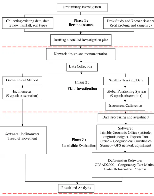
in brief the experimental research for landslide monitoring. There are three phases in
this research methodology as shown in Figure 1.1. The first phase includes the
reconnaissance, topographic investigation and preliminary analysis of existing
geotechnical data such as boring result. The methodology starts by carried Literature
review on GPS technology and geotechnical and their applications in landslide
monitoring. This followed by choosing the suitable landslide location which is
relevant to the research scopes. Next, soil probing using Macintosh probe techniques
and soil sampling test in laboratory work was carried out at the landslide area.
Second phase is field investigation which includes set up monitoring networks
design with respect to the specified monitoring technique. Than followed by the
determination of control stations and plant monitoring stations location on the study
area. Next is the field measurements that involve the GPS technique such as static,
fast static, real time kinematic and real time kinematic network positioning mode and
inclinometer techniques at the control and monitoring stations within certain epochs
(after completing the monuments at the test sites).
Third phase is landslide assessment that includes the strategies of data
processing and deformation analysis. The processing and analysis of GPS data is done
to detect any deformation between first epoch and rest of the epochs using
deformation software such as GPSAD2000 and Static Deformation Program. While,
for the inclinometer data are processed and analysed using In-Site software. This
followed by the detection of deformation based on geotechnical data using
inclinometer instrument. Finally, the rate of displacement from both GPS and
inclinometer techniques are compared and analysed.
1.6
Significant of Study
The contribution of this study is summarized as follows. Firstly, the precise GPS
survey techniques are utilized to provide sub-centimetres precision for the slope
stability analysis. Secondly, the suitability and effectiveness GPS techniques are
utilized in deformation detection for landslide monitoring in Malaysia. The method of
deformation applied in this study provides a perspective to the relevant authority or
8
Preliminary Investigation
Deformation Software:
GPSAD2000 – Congruency Test Method
Static Deformation Program
Desk Study and Reconnaissance
(Soil probing and sampling)
Drafting a detailed investigation plan
Geotechnical Method
Inclinometer
(9 epoch observation)
Software: Inclinometer
Trend of movement
Satellite Tracking Data
Global Positioning System
(9 epoch observation)
Data processing and adjustment
Instrument Calibration
Phase 3 :
Landslide Evaluation
Phase 2 :
Field Investigation
Software :
Trimble Geomatic Office (latitude,
longitude,height), Topcon Tool
Office – Geographical Coordinates
Starnet – GPS network adjustment
Data Collection
Phase 1 :
Reconnaissance
Collecting existing data, data
review, rainfall, soil types
Network design and monumentation
Result and Analysis
The GPS and inclinometer techniques implemented in this study will provides
better information of position changes in horizontal and vertical. The processing
strategy of the technique should be obtained for true deformation without error or
bias. This study customizes data processing algorithm for deformation which can
provides a precise result. The benefit of this approach is that it verifies the reliability
of the GPS technique for precise application such as landslide deformation
monitoring.
The other contribution is to apply GPS and inclinometer techniques result for
deformation monitoring in order to give an early result of the area that prone to
landslide phenomenon. This could give benefit to the people at the surrounding area
for an early prevention step and to reduce the damage caused by landslide.
1.7
Organisation of Thesis
This thesis consists of six chapters, appendices and a list of references.
Chapter 1 explains the related introduction of this study including background of
study, objectives, scopes and contribution of the study.
Chapter 2 discusses the issues of landslide phenomenon in detail, including the
definition of landslide phenomenon in various perceptions, existing characteristics of
landslide, and its connection with slope failure, landslide occurrence factors, the
investigation methods and the examples of landslide phenomenon and the
investigation methods in Malaysia.
Chapter 3 explains in depth the details of the scientific methods in landslide
monitoring such as the instrumentation that being used in this study which are GPS
and inclinometer. A detail explanation of both techniques is discussed. This include a
discussion reviewing the GPS segment; the error sources involved in using GPS;
positioning method and mechanism; processing differenced data; baseline solution;
GPS dilution and GPS processing packages. Summaries of basic concept and
10
concepts and methods of deformation analysis, types of network monitoring and
techniques used for deformation monitoring are also discussed in this chapter.
Chapter 4 focuses on the observation procedure and research methodology.
The observation procedure consists of network configuration, control network,
monument design, types of GPS observation, and number of inclinometer casing
based on the landslide rank from the ROM scale that has been developed Marzita
(2000). This chapter also explained the operational scheme of combining the GPS and
geotechnical methods for the landslide investigation. The implementation and
application of the operational procedures using both GPS and geotechnical method at
one existing landslide area that has been chooses as a sample. The detail explanation
of the network design, monitoring campaign, processing and others related processes
are discussed in this chapter. In the first sub-chapter, the preliminary study of the
types of soil and laboratory test is highlighted in this chapter. The next section covers
the network design and designation of the monitoring points. This chapter also briefly
presents the observation procedures and analyses of processing GPS data for
deformation monitoring landslide phenomenon using few GPS processing packages
such as Trimble Geometry Operations (TGO), Topcon Tools and STARNET
software.
Chapter 5 explains the results and discusses the work accomplished. The
analysis consists of GPS network adjustment, GPS network deformation analysis,
processing strategy using GPSAD2000 and Static Deformation Software, and the
inclinometer detection.
Finally, Chapter 6 draws an overall conclusion and some important
recommendation to future investigation of landslide monitoring in Malaysia. These
BIBLIOGRAPHY
Abdul Majid, A. K. and Ghazali, D. (1995).
The Intergration of GPS and GIS
. Final
Report Research Project UPP Vot 60699.
Abd. Majid, S., Sum, C. W. and Ferdaus, A. (1998).
Gelongsoran Tanah Di Bukit
Antarabangsa, Hulu Kelang, Selangor
. Geological Survey Department
Malaysia. Minstry of Primary Industries.
Abidin, H. Z. , Adreas, H, Gamal M., Surono and Hendrasto, M. (2004a).
On the use
of GPS survey method for studying land displacements on the landslide prone
areas.
FIG Working Week. Athens Greence. May 2004.
Abidin, H. Z. , Adreas, H, Gamal M., Surono and Hendrasto, M. (2004a).
On the use
of GPS survey method for studying land displacements on the landslide prone
areas.
FIG Working Week. Athens Greence. May 2004.
Abidin, H.Z., Adreas, H, Gamal M., Djaja R., Murdohardono D., Rajiyowiryono H.
(2006).
Studying Landsubdsidence of Bandung Basin (Indonesia) Using GPS
Survey Method
. Survey Review.Vol.38,No.299.January.pp 397-405.
Absolute Instrument Systems, (2011). Direct & Inverted Pendulum. Available at:
http://www.aisys.com.sg/items/
Ahmad F. N. (2009).
MyRTKnet
. MAP ASIA 2009. August 18 - 20, 2009. Singapore.
Aimil, Ltd (2011). Hanging Pendulum. Available at
http://www.aimil.com/products.aspx? ProductID=114
Amir, H., Fatt, C. L., Hui, T. K. (1999). Rainfall And Erosion Study in Cameron
Highlands. In. Roslan, Z.A and Tew, K. H. (edit.).
Compilation of Presented
Research Papaers On Soil Erosion Issues In Malaysia.2
ndEdition
. VT Soil
Erosion Research & Concultancy. Selangor. 1 – 24.
Armenakis, C and Faig, W., (1988). Slope monitoring by integrating
photogrammetry with predicted data.
Proceedings of the 5
thInternational (FIG)
Symposium On Deformation Measurement and 5
thCanadian Symposium on
Mining Surveying and Rock Deformation Measurements
. Fredericton, New
298
Ashok, W. (2001).
GPS/GIS in India
. Applied Field Data System Inc. Houston.
Ashtech (1997).
GG24
TMOEM Board and Sensor. GPS + GLONASS Reference
Manual
. No. 630098, Revised Version B, Sunny, CA: Ashtech.
Askury, A. K. (1999a).
Laporan Tinjauan Awal Kejadian Tanah Runtuh di Bukit
Besar, Kuala Terengganu
. Jabatan Penyiasatan Kajibumi Malaysia
Terengganu. No.Laporan: Eng Geo/TRG 1/1999.
Askury, A. K. (1999b).
Laporan Kegagalan Cerun di km 69.54, Jalan raya Timur
Barat, Gerik, Perak
. Jabatan Penyiasatan Kajibumi Malaysia Terengganu.
No.Laporan: Eng Geo/TRG 5/1999.
Askury, A. K. (1999c).
Laporan Geologi Kejuruteraan terhadap kejadian tebing
runtuh di km 71.83, Jalan raya Timur Barat, Gerik, Perak
. Jabatan Penyiasatan
Kajibumi Malaysia Terengganu. No.Laporan: Eng Geo/TRG 4/1999.
Azfar, N.A. (2010).
Geotechnical Instrumentation for Monitoring Purpose of Majlis
Peperiksaan Malaysia.
Tesis Sarjana Muda. Fakulti Kejuruteraan Awam.
Universiti Teknologi Malaysia. Johor.
Berita Harian (2002), Pembangunan Cerun Bukit Terdedah Pelbagai Risiko. 28
November 2002.
Bernama
(2008). Sejarah Tanah Runtuh di Hulu Klang dan Sekitarnya. 06 Disember
2008. Received 3 March 2003. http://www.bernama.com/bernama/v3/bm/
news_lite.php? id=376746
Bhandari, R.K. (1988). Special lecture: Some practical lessons in the investigation
and field moniroting of landslides. In Landslide, Bonnard, C. (Edit.).
Proceedings of the 5
thInternational Symposium on Landslides
. 10 – 15 July.
Vol.3. A.A.Belkema: Netherlands. 1435 – 1458
Bong C. N. (2000).
GPSAD2000 – Sistem Perisian Untuk Pelarasan Vektor GPS,
Pengenanan Deformasi Dan Analisis Visualisasi
. Tesis Sarjana. Fakulti
Kejuruteraan dan Sains Geoinformasi. Universiti Teknologi Malaysia. Johor.
Brabb, E.E. (1984). Innovative Approaches To Landslide Hazard Mapping.
Proceedings IV International Symposium Landslides
, Toronto, v.1, 307-324.
Brabb, E.E. (1989). Landslides: Extent and economic significance in United State.
Brand, E. W. (1989). Occurrence and significance of landslides in Southeast Asia.
Landslides: Extent and Economic Significance. Brabb, E.E. and Harrod, B. L.
(Edit.).
Proceedings of the 28
ThInternational Geological Congress: Symposium
on Landslides
. A.A.Balkema: Netherlands. 303 – 324.
Brennan, M. E. (1999).
Remote Sensing Techniques Applied To Landslide Studies
.
USGS Geological Survey Geologic Hazards Landslide.
Carrara, A., Cardinali, M., Guzzetti, F., dan Reichenbach, P., (1995). GIS-Based
Techniques For Mapping Landslides Hazard.
Geografical Information System
in Assessing Natural Hazards
, Academic Pub., Dordrecht, Netherlands.
Caspary, W.F. (1987).
Concepts of Network and Deformations Analysis
. University
of New South Wales: Monograf.
Cheng, H. H. (2000). Photogrametric Digital Data Processing of Tsao-Lin Big
Landslide. Received 3 March 2003. http://www.gisdevelopment.net/
aars/acrs/2000/ps1/ps102pf.htm
Chen, Y.Q. and Chrzanowski, A. (1986). An overview of the physical interpretation
of deformation measurements. Deformation Measurement Workshop, MIT,
Boston, Oct.31-Nov,1.Proceedings (MIT),pp 207-220.
Chrzanowski, A., dan Secord, J.M. (1983). Report of The Ad Hoc Committee on The
Analysis of Deformation Surveys.
Proceedings of The FIS XVII International
Congress
. June 19-28. Sofia, Bulgaria: Pape No. 605.2.
Chrzanowski, A (1986). Geotechnical and Other Non-Geodetic Methods in
Deformation Measurements.
Proceedings Deformations Measurements
Workshop: Modern Methodology in Precise Engineering and Deformation
Survey – II
. Bock, Y (Edit.). Massachusetts Institute of Technology.112 – 152.
Chrzanowski, A., Chen, Y. Q. and Secord, J.M (1986). Geometrical Analysis of
Deformation Surveys.
Proceedings Deformation Measurements Workshop:
Modern Methodology in Precise Engineering and Deformation Surveys – II
.
Cambridge. Massachusetts Institute of Technology, 170-206.
Coffey (Malaysia) Sdn. Bhd. (2001).
Slope failure report. Section 5, Wangsa Maju,
Kuala Lumpur.
300
Coe, J.A., Godt, J.W., Ellis, W.L., Savage, W.Z., Powers, P.S., Varnes, D.J.,
Tachker, P. (2000).
Seasonal Movement of The Slumgullion Landslide As
Determined From GPS Observation July 1998 – July 1999
. Open File Report
00-101. U.S Geological Survey.
Coe, J.A., Ellis, W.L., Godt, J.W., Savage, W.Z., Savage, J.E., Michael, J.A., Kibler,
J.D., Powers, P.S., Lidke, D.J. and Debray, S. (2003).
Seasonal Movement of
The Slumgullion Landslide Determined From Global Positioning System
Surveys and field instrumentatiuon July 1998 – March 2002
. Journal of
Engineering Geology. Vol 68. pg 67-101.
Corbeanu, H., Brikowski, T. and Aiken, C. (2000). Landslide Monitoring in
Romania.
GPS world
. March. 38 – 42.
Craig, R. F. (1993). Mekanik Tanah Edisi Keempat. Universiti Teknologi Malaysia.
Crozier, M. J. (1986).
Landslides : Cause, Consequences & Environment
. Croom
Helm. London. UK.
Cruden, D. M. et.al. (1989). Landslides: Extent and economic significance in
Canada. Landslides: Extent and Economic Significance. Brabb, E.E. and
Harrod, B. L. (Edit.).
Proceedings of the 28
ThInternational Geological
Congress: Symposium on Landslides.
A.A.Balkema: Netherlands. 1 – 24.
Dana H. P. (1994). Global Positioning System Oveview.
Department of Geography,
University of Texas at Austin. Received 11 March 2003.
http://www.colorado.edu/geography/gcraft/notes/gps/gps_f.html
Donald, W. T. (1975).
Causes, Mechanisms, and Prediction of Landsliding In
Seattle
. Dissertation. University of Washington.
Dunnicliff, J. (1988).
Geotechnical Instrumentation for Monitoring Field
Performance
. A Wiley-Intersciences Publication. New York. USA.
Durham Geo-Enterprises (2011). Soil Strainmeter. http://www.slopeindicator.com/
instruments/soilstrainmeter.html
Erol S., Tait M., Erol B., and Ayan T. (2004).
1-D and 3-D analysis of deformations
in engineering structures using GPS and terrestrial data
. In Int. Federation of
Surveyor (FIG) INGEO 2004. Regional Central and Eastern European Conf. on
Eng. Surveying. Bratislava, Slovakia.
Forward, T.A (2002).
Quasi-Continuous GPS Steep Slope Monitoring. A
Multi-Antenna Array Approach.
Ph.D Thesis, Curtin University of Technology, pp
Fujii Y. and Shinde, Y. (2006).
Four dimensional monitoring of ground subsidence
in Kawasaki, Japan by repeated GPS survey
. In 3
rdInt. Assoc. of IAG/12
thInt.
FIG Symp, Baden.
Gassner, G., Wieser, A., Brunnerm F. K.,. (2002). GPS Software Development For
Monitoring of Landslide.
Proc. FIG XXII. Deformation Measurement and
Analysis II.
Congress Washington. D.C. m.s. 12.
Gili, J. A., Corominas, J. and Rius, J. (2000). Using Global Positioning System
techniques in landslide monitoring.
Engineering Geology
. 167 – 192.
Gobbet, D.J. (1964). The Lower Paleozoik Rock of Kuala Lumpur.
Malaysia
Federal Museums Journal
, 9, m/s 67-79.
Gue, S. S. and Tan, Y.C.(2002). Mitigating the Risk of Landslide on Hill-Site
Development in Malaysia. Sarawak. July 22 – 25.
WEC
. 1 – 9.
Halim, S. and Mohd, S. I. (2003). An Interface For Deformation Detection Using
STARNET. International Geoinformation Symposium 2003. Kuala Lumpur
Malaysia 22-24 October.
Halim, S. and Bong, C. N. (2000). GPSAD2000- A Software System for GPS
Baseline Adjustment, Deformation Detection and Visualization Analysis.
Proceeding of 4
thAsia Pasific Structural Engineering & Construction
Conference (ASPEC 2000)
. Kuala Lumpur. 13-15 September 2000.
Halim, S. (1997). A Flexible Analysis Procedure for Geometrical Detection of
Spatial Deformation. The Photogrammetric Record. Volume 15. Issue 90. Pp
841-861.
Hamlee, I. dan Frederik, T. (2000).
Siasatan Kestabilan Cerun di Sepanjang
Jalanraya dari Km 14 higga Km 66 Tambunan – Kota Kinabalu Sabah.
dlm.
(Khoo Kay Khean, ed.). Volume 1. Jabatan Mineralogi dan Geosains Malaysia.
Hasan J., Azhari M., and David C. (2010)
The Malaysia Real-Time Kinematic GNSS
Network (MyRTKnet) In 2010 and Beyond
. Proceeding of FIG Congress
2010.Sydney, Australia, 11-16 April 2010.
Hill, C. D. and Sippel, K. D. (2002). Modern Deformation Monitoring: A Multi
Sensor Approach.
FIG XXII International Congress
. Washington: USA.April
19-26.1–12.
302
Hoftman, W.B. (1992). GPS – theory and practice. Springer, Wien New York.
Hothem, L.D. (1986). Subsidence Studies With GPS: Planning and Field Operation
Aspects. In:
Proceedings Deformation Measurement Workshop Modern
Methdology in Precise and Deformation Surveys – II
. Oct.31-Nov.1. Ed. By
Yehuda Bock. Massachusetts Institute of Technology. Cambridge. MA:
397-415.
Hui, T.K, (1999).
Production of Malaysian Soil Erodibility Nomograph in Relation
to Soil Erosion Issues
. VT Soil Erosion Research & Concultancy. Selangor.
Hunt, R. E. (1984).
Geotechnical Engineering Investigation Manual
. McGraw-Hill
Book Company. New York. USA.
Hutchinson, J.N. (1988). General report: Morphological and geotechnical parameters
of landslides in relation to geology and hydrogeology. In Landslide, Bonnard,
C. (Edit.).
Proceedings of the 5
thInternational Symposium on Landslides
. 10 –
15 July. Vol.1. A.A.Belkema: Netherlands. 3 – 36.
Intergovernmental Committee On Surveying & Mapping (ICSM), (2011). Surveying
For Mapping – Section 4, Surveying Using GPS and Conclusion. Available at:
http://www.icsm.gov.au/mapping/surveying4.html
Intec Marketing Services (2010). Soil Testing Equipment Mackintosh Probing Kit.
Available at: http://www.intec.com.my/product/soilequip/soil.html
Jabatan Penyiasatan Kajibumi Malaysia (1975).
Peta Hidrogeologi Semenanjung
Malaysia.
Cetakan Pertama. Skala 1:50,000.
Jabatan Penyiasatan Kajibumi Malaysia (1993).
Bedrock Geology of Kuala Lumpur:
Geological Map Peninsular Malaysia Wilayah Persekutuan.
Series L8010.
Scale 1: 25000
Jabatan Ukur dan Pemetaan Malaysia (1989).
Peta Topografi
. Kuala Lumpur. Siri
L7030. Lembar 3666. Skala 1:50,000.
Jabatan Ukur dan Pemetaan Malaysia (2003). Tapak Ujian EDM & GPS
Semenanjung Malaysia dan Wilayah Persekutuan Labuan. Pekeliling Ketua
Pengarah Ukur dan Pemetaan. 2003.
Jasmi, A. T., Azlikamil, N. and Zainal, A. H. (2001). Landslide Hazard Zonation
Mapping of Selangor.
Buletin Ingenieur
. Quartery 1/4 March. 26 – 40.
Jasmi, A. T. (2000).Landslide Hazard Zonation Mapping Using Statistical Approach.
In The, G. H., Periera, J. J. and Ng, T. F.
Proceedings of Annual Geological
Conference 2000
. Geological Society of Malaysia. 235 – 240.
Kalkan, Y., Baykal, O., Alkan, R. M., Yanalak, M., and Erden, T. (2002).
Deformation Monitoring with Geodetic and Geotechnical Methods: A case
study in Ambarli Region.
International Symposium on GIS. Istanbul
. Turkey.
Sept.23-26.1 – 12.
Kane, W. F. and Beck, T.J. (1999). Advance in slope instrumentation : TDR and
remote data acquisition systems.
Field Measurements In Geomechanics, 5
thInternational Symposium on Field Measurement in Geomechanics.
Singapore.
101 – 105.
Kelly, J. (2000). PPS versus SPS: Why Military Applications Require Military GPS.
GPS World. January 2000.
Khamarrul, A. R. (2004).
Analisa Deformasi Tanah Runtuh Menggunakan Teknologi
GPS.
Tesis Sarjana. Fakulti Kejuruteraan dan Sains Geoinformasi. Universiti
Teknologi Malaysia.
Kehew, A.E. 2006.
Geology for Engineers and Environmental Scientists
. 3rd
Edition. Prentice.
Kelly, J. T. (2000).
Military – Precision or Standard: PPS versus SPS?
GPS World.
January 2000. Pp 28–35.
Kovari, K. (1988). General Report: Methods