WIRELESS SESOR ETWORK
FOR SMART POWER MAAGEMET
MOHD SHAHRIZAL BI RUSLI
WIRELESS SENSOR NETWORK FOR SMART POWER MANAGEMENT
MOHD SHAHRIZAL BIN RUSLI
A project report submitted in partial fulfilment of the requirement for the award of the degree of
Master of Engineering (Electrical – Electronics and Telecommunication)
Faculty of Electrical Engineering Universiti Teknologi Malaysia
iii
iv
ACKOWLEDGMET
Alhamdulillah, praise be to Allah, the Most Merciful and the Most Compassionate. It is by God’s will, I was able to complete this project within the stipulated time. This thesis wouldn’t have been more successful without the help and guidance of so many people. The most important person is none other than my supervisor, Dr. Mohd Nasir bin Ibrahim. He had always been there to guide me with patience throughout the progress of my project. Be it understanding the system design to the verification process, his support throughout this project has been the most encouraging.
I would also like to extend my appreciation to the following people: my father, Rusli Yusof, my mother, Mariam Hashim, my sister, Maisarah and my brother, Muhammad Haziq for their strong support throughout my studies.
My fellow colleagues, Asmida, Mohd Adib, Samsul, Mohd Sarfudin, Zaharah, Syaári, Salman, Mastura and others whose cooperation have been imperative in ensuring the success of the project, was also of great help. They have
always been there whenever problem arises. Working with them taught me a lot about hardware design and how to troubleshoot problems.
v
ABSTRACT
vi
ABSTRAK
Wireless Sensor etwork merupakan aplikasi perhubungan tanpa wayar yang terkenal pada masa kini sejajar dengan perkembangan teknologi yang pesat. Antara contoh aplikasi yang menggunakan teknologi ini termasuklah kawalan automatik, bacaan meter secara automatik, pengurusan kuasa elektrik dan sebagainya. Wujudnya sistem ini dapat memberikan kemudahan, meningkatkan keberkesanan kerja dan menyediakan pengurusan sistem yang teratur. Matlamat projek ini adalah untuk membangunkan sebuah sistem pengurusan kuasa elektrik bersepadu. Sistem komunikasi dibangunkan menggunakan jaringan radio frekuensi (RF) tanpa lesen di mana komunikasi antara unit kawalan utama dan cawangan pengesanan adalah berasaskan penggunaan arus elektrik yang dikesan oleh setiap cawangan tersebut. Penerimaan data oleh unit kawalan utama dari cawangan pengesanan boleh dilakukan secara round robin ataupun interrupt service routine (ISR). Pengiraan arus dan kuasa elektrik yang berkadaran dengan nilai yang diterima dilakukan oleh unit kawalan utama dan seterusnya disimpan di pangkalan data unit kawalan itu sendiri. Unit ini mampu berkomunikasi dengan sebanyak mana cawangan pengesanan yang ada selagi jaraknya adalah dalam lingkungan 40 meter bagi kawasan tertutup dan 120 meter di kawasan terbuka tanpa halangan. Pembangunan perisian dan peranti elektronik sistem dilakukan secara serentak untuk mengoptimumkan masa yang
diambil bagi melengkapkan projek. Antara langkah-langkah penentusahan sistem yang diambil termasuk penyenggaraan peranti pengesan arus yang digunakan dan ujikaji pengukuran arus beberapa perkakasan elektrik seperti alat pengubah voltan
vii
TABLE OF COTETS
CHAPTER TITLE PAGE
DECLARATIO ii
DEDICATIO iii
ACKOWLEDGMET iv
ABSTRACT v
ABSTRAK vi
TABLE OF COTETS vii
LIST OF TABLES x
LIST OF FIGURES xi
LIST OF ABBREVIATIOS xiv
1 ITRODUCTIO
1.1 Introduction 1
1.2 Problem Statements 3
1.3 Objectives 4
1.4 Scope of Project 4
1.5 Sensor Node Features 6
1.5.1 Wireless Sensor Network for
Smart Power Management System Specifications 7
1.5.2 System Requirements 7
viii
2 LITERATURE REVIEW
2.1 WSN in Power Management 9
2.2 Current Measuring Devices 13
2.2.1 Hall-Effect Current Monitoring Clamp
and Voltage Meter 13
2.2.2 Fluke Current Clamp 14
2.3 Hardware Specifications 15
2.3.1 Hall-Effect Current Sensor, CSLA2CD 16
2.3.2 PIC16F877A (28-Pin 8-Bit CMOS
FLASH Microcontrollers) 17
2.3.3 XBee OEM series 2 RF Modules 19
2.4 Software Specifications 22
2.4.1 Visual Basic .NET 23
2.4.2 Proteus 7 Professional 23
2.4.3 Mikroelektronika (MikroC PRO) 24
2.4.4 PICkit 2 v2.55 Compiler 24
2.4.5 X-CTU Software 24
3 METHODOLOGY
3.1 Introduction 26
3.2 Hardware Development 30
3.2.1 WSN for Power Management
Sensor Node Circuit Design 30
3.2.2 WSN for Power Management
Main Controller Circuit Design 34
3.3 Software Development 36
3.3.1 Visual Basic 6.0 .NET 37
3.3.1.1 COM Port Function 37
3.3.1.2 Request Measurement Function 38
3.3.1.3 dataProcess Function 38
3.3.1.4 listNodeDetails Function 39
3.3.1.5 Timer Function 39
ix
3.3.3 Proteus 7 Professional 42
3.3.4 MikroElektronika (MikroC PRO) 44
3.3.5 PICkit 2 v2.55 46
3.3.6 X-CTU Software 50
4 RESULTS AD DISCUSSIO
4.1 Introduction 57
4.2 Circuit Testing 58
4.2.1 Output Voltage Range of
Hall-Effect Current Sensor, CSLA2CD 58
4.2.2 Program Testing of
Data Frame Set in Hyperterminal 60
4.2.3 Test USART in Proteus 7.0 Professional 62
4.2.4 Basic Test of Wireless Communication
using XBee Module 66
4.3 Programming of Wireless Sensor Network
for Power Management 66
4.3.1 PIC Programming 67
4.3.2 Visual Basic .NET Programming 72
4.4 Achievement of Project 76
4.5 Problems and Constraint During Project 79
5 COCLUSIO AD RECOMMEDATIOS
5.1 Introduction 80
5.2 Conclusion 80
5.3 Limitations of the Project 81
5.4 Suggestions for Future Works 82
REFERECES 84
x
LIST OF TABLES
TABLE O. TITLE PAGE
2.1 Comparison of wireless devices 11
2.2 PIC16F877A pin-out description 18
2.3 Pin assignment for XBee OEM series 2 RF Module 20
xi
LIST OF FIGURES
FIGURE O. TITLE PAGE
1.1 General system diagram 5
1.2 Functional block diagram 6
2.1 Demand-side management with
peak flattening and averaging 10 2.2 Comparison among wireless devices
in terms of data rate, cost/complexity
and power consumption 12 2.3 ZigBee protocol in OSI layer 13 2.4 Hall-Effect current monitoring clamp 14 2.5 Fluke current clamp 15 2.6 USB data acquisition, LabJack 15 2.7 Hall-Effect Current Sensor, CSLA2CD 16
2.8 PIC16F877A 17
2.9 PIC16F877A pin configuration 18 2.10 XBee OEM series 2 RF Module 20
2.11 API frame 21
2.12 Various mode of operation for
XBee OEM RF Module 22
3.1 System design flow 27
xii
3.4 Sensor node circuit design 32
3.5 PCB layout of sensor node circuit 33
3.6 WSN for Power Management sensor node block diagram 33
3.7 WSN for Power Management sensor node circuit 34
3.8 Main controller block diagram 35
3.9 Main controller schematic diagram 35
3.10 Main controller layout circuit 36
3.11 XBee module for the main controller 36
3.12 Form window 40
3.13 Code window 41
3.14 MySQL database 42
3.15 Design of main circuit using ISIS 7 Professional 43
3.16 Simulation of circuit using ISIS 7 Profesional 44
3.17 PCB layout of main circuit using ARES 7 Profesional 44
3.18 Mikroelektronika (MikroC PRO) 45
3.19 PICkit 2 v2.55 46
3.20 USB programmer detection 47
3.21 PIC microcontroller detection 48
3.22 Loading .hex file 49
3.23 Successful code writing into PIC microcontroller 50
3.24 Connecting XBee module to PC 51
3.25 Setup X-CTU 51
3.26 PCB setting tab 52
3.27 Modem detection 53
3.28 Modem Configuration tab 54
3.29 Syntax of AT command 55
xiii
4.1 Measurement of output voltage
from CSLA2CD sensor 59 4.2 Graph Volt versus Ampere of CSLA2CD 60 4.3 Request frame from the main controller 61 4.4 Response frame from sensor node 61 4.5 Output voltage received from sensor node 61 4.6 Data received at Hyperterminal 62 4.7 Connection from PIC to PC 63 4.8 USART connection in PROTEUS 64 4.9 Flowchart of simulation 65
4.10 Simulation result 65
4.11 Communication between two PCs 66 4.12(a) Request flowchart for WSN
for Power Management 71
4.12(b) Response flowchart for
WSN for Power Management 71
4.13 GUI window when system initialized 77 4.14 GUI window after connected to COM port
and measurement value received 78 4.15 Database pwr_mgmnt with two linked tables 78 5.1 Basic connection for power single-phase,
2-wire – direct connect to
xiv
LIST OF ABBREVIATIOS
ADC - Analog-to-Digital Converter
ADRESL - Address Low Register
ADRESH - Address High Register
API - Application Programming Interface
GEAR - Geographic and Energy Aware Routing
GUI - Graphical User Interface
IC - Integrated Chip
I/O - Input / Output
ISM - Industrial, Scientific and Medical
ISR - Interrupt Service Routine
LOS - Line-of-Sight
MAC - Medium Access Layer
OSI - Open System Interconnection Reference
PC - Personal Computer
PHY - Physical Layer
RAM - Random Access Memory
RF - Radio Frequency
UART - Universal Asynchronous Receiver / Transmitter
USART - Universal Synchronous / Asynchronous
Receiver / Transmitter
USB - Universal Serial Bus
VB .NET - Visual Basic .NET
WAMR - Wireless Automated Meter Reading
CHAPTER 1
ITRODUCTIO
1.1 Introduction
It is expected that in future, the demand for energy will escalate and this will
require either new source of energy or new power plant constructions. And the cost
of providing power is also increasing due to higher fuel prices and increases in the
cost of construction and capital expenses. People are even now investigating other
natural sources as new energy sources of power plant such as coal, wind, solar and
fuel cells to ensure that global energy supply could be increased and maintained.
However, one important basic way of preserving the energy supply that has
been ignored by the researchers is the management of power distribution. This is a
very important subject in the area of energy conservation. Wireless sensor network
(WSN) can be greatly utilized in the area of demand-side management. It can slow
down or decrease maximum energy consumption to increase energy efficiency. One
way of realizing it is by setting the system to monitor and control low power and
2
In the case of excessive demand of electrical supply, some basic appliances
are critically in need of power and should be allowed to operate. A system that can
differentiate between high power and low power usage can be created at every sensor
node and allows only low power devices to be ON for that particular period.
This is where WSN comes in. By controlling the appliances with minimum
anticipation of users, it can greatly improve energy efficiency and utilities by
creating load management. Wireless communication protocol is used to realize this
system. WSN is a collection of wireless nodes with sensing capabilities, which is
distributed in a bounded area and is used to monitor either physical or environmental
conditions. These nodes can communicate with one another and use each other as a
path through the network in order to communicate with a controller or even a
gateway.
One obvious advantage this system has over the existing conventional wired
systems is the last-mile connectivity. In term of advantages WSN can offer above all
other wireless sensor network is that it offers power management for multiple
industries, wireless automated meter reading (WAMR) and electric systems
monitoring.
This project is focusing on developing a power management system using
WSN. It consists of a microcontroller, a standard wireless module as well as sensing
elements that can communicate wirelessly with the control unit for monitoring. The
communication is in full duplex mode. The communication will consist of data
transfer that controls the node operations. PIC16F microcontroller is used as the
controller at each node, XBee series 2 module (with ZigBee protocol) is chosen as
the wireless protocol, Hall-effect sensor from Honeywell Inc. is used as a sensing
3
The advantage of using this PIC16F is that it is a 8-bit microcontroller that
provides extra features that do not require major changes of pin configuration when
future works is to be done, apart being the most common and widely used
microcontroller. As for XBee, the main advantage is that it requires very less amount
of power so it can be operated from battery. Power consumption has been of interest
for WSN since the system is required to endure as long as possible with small power
consumption. So, choosing the XBee as wireless protocol is believed to be the best
choice.
1.2 Problem Statements
There are three problem statements carried out of this project:
1. Having automated power management system will make efficient energy
consumption, speed and reduced personnel intervention in making
decision and most importantly monitoring the activity at the sensing
nodes.
2. For intelligent house application, the main controller can optimize the use
of electrical energy throughout the house by wireless sensor network
which will provide information of energy consumption for each part of
the house. Conventional houses do not apply this.
3. In most housing areas, meter reading is still done manually. Having
wireless automated meter reading implemented in place will reduce
4
1.3 Objectives
There are three objectives of this project:
1. The main controller in the wireless sensor network using unlicensed
frequency will identify and monitor current flow activity at each sensing
node to make the efficient use of power.
2. This project also strives at understanding current measurement in sensor
nodes. Power consumed in the network can be calculated depending on
the implementation of the WSN.
3. To design and build an efficient sensor node that will automatically
measure current flow of a particular device, so that it can make efficient
power management.
1.4 Scope of Project
This project consists of two parts that are the sensing node and the main
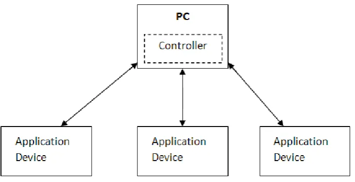
controller unit. As shown in Figure 1.1, a group of application devices are connected
to a main controller which monitors the activity of measured parameters at each
sensing node. In the sensing node part, it has several functioning devices such as
hall-effect current sensor, microcontroller and the X-Bee series 2 RF module (acts as
transmitter and receiver). The controller unit consists of X-Bee series 2 RF module
(also acts as transmitter and receiver), serial interface board, personal computer with
Visual Basic.Net (VB.NET) program and MySQL database.
The idea of this project is to implement wireless protocol communication
using Zigbee wireless protocol which applies unlicensed frequency band of 2.4GHz
5
series 2 RF module. Current measurement in assigned devices is done by Hall-Effect
current sensor placed in the sensor node. The measurement data will then be injected
into the PIC microcontroller for monitoring purpose. The microcontroller will
process the data and transmit it to the main controller wirelessly via transceiver XBee
series 2 RF module. However, measurement request must initially come from the
main controller unit. Upon receiving the response data from a particular sensor node
via another transceiver XBee series 2 RF module, manipulation of data will take
place using Visual Basic .NET and the data is then stored in MySQL database.
Figure 1.1: General system diagram
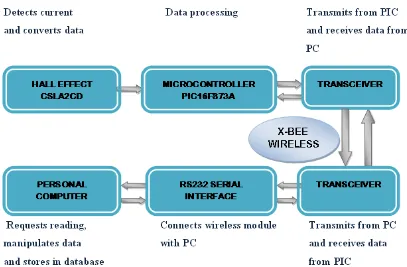
Figure 1.2 below shows the functional block diagram of the whole system.
This system is designed to operate in half duplex mode. It initially starts from the
request made by the control unit to a dedicated sensor node. The dedicated sensor
node will then respond to the request and transmits requested data to the main
controller unit. The XBee RF module transmits data in 2.4GHz unlicensed frequency
6
Figure 1.2: Functional block diagram
1.5 Sensor ode Features
The sensor nodes in this system will make a fast, reliable current
measurement. With the mobility of the sensor within the indoor range of 40m and
outdoor line-of-sight of 120m, and operating at 2.4 GHz wireless frequency band,
many applications can be measured. It is also very suitable for intelligent house
application where the use of current inside the house can be monitored and
controlled. The sensor applied uses no complex circuitry except for high current and
high voltage purposes. Also, it provides linear output when current is sensed through
7
1.5.1 Wireless Sensor etwork for Smart Power Management System Specifications
Remote function: Senses current when requested by control unit and
transmits measurement to control unit wirelessly via Zigbee protocol.
• Frequency: 2.4 GHz
• Range:
• Indoor/urban: up to 100 feet (40m)
• Outdoor: up to 300 feet (100m)
• Operating voltage:
• PIC microcontroller: 5V
• XBee series 2 RF module: 3.3V
• Hall-Effect current sensor: 6 – 12V
• Power: 6.5V batteries
• Transmit power: 2mW (+3dBm)
• Receiver sensitivity: -96dBm
• Data rate: 2500 bit per second (bps)
• Interface: Serial communication
• Graphical user interface (GUI): VB .NET
• Database: MySQL
1.5.2 System Requirements
• Microsoft Visual Basic 6.0 .NET
• Windows 98,2000,ME,XP
8
• MySQL database
• X-CTU software
1.6 Outline of Final Report
This final report consists of five (5) chapters. The first chapter describes the
background of the related issue on power management, problem statements,
objectives scope of project, project specification and requirements. The second
chapter will cover about the background of remote control, literature review as well
as wireless sensor network for smart power management application available in the
market. The third chapter consists of the theory about the software and hardware
implemented in this project. The main points to be discussed in this chapter are the
methodology of this project. Two major parts will be looked into, that are software
development and hardware development. Chapter four will discuss on the results
obtained as well as general discussion on the result. Problems occurred throughout
the project will also be discussed. The last chapter is about the summary and
conclusion of the project. In this chapter, future work will also be suggested for the
benefits of research and development of this power management using wireless
84
REFERECES
Asmida binti Ismail, “Powerpoint Remote Control System,” Final Year
Undergraduate Project, Universiti Teknologi Malaysia, May 2008
Axel Sikora, Prof. Dr.-Ing. “ZigBee Competitive Technology Analysis,” ZigBee
Alliance
Deborah Estrin, “Wireless Sensor Networks: Application Driver for Low Power
Distributed Systems,” ISPLED‘OI, August 2001, ACM
F.L. Lewis, “Wireless Sensor Network,” in Smart Environments: Technologies,
Protocols and Applications, 2004
Md. Rezaul Hoque Khan, Roberto Passerone, David Macii, “FZepel: RF-level Power
Consumption Measurement (RF-PM) for Zigbee Wireless Sensor
Network-Towards Cross Layer Optimization,” IEEE, 2008
Microsoft Visual Basic 6.0 .NET reference manual
MikroC PRO for PIC software manual from Mikroelektronika, Inc.
Muhammad Ali Mazidi, Rolin D. McKinlay and Danny Causey, “PIC
Microcontroller and Embedded Systems Using Assembly and C for PIC18,”
Pearson International Edition, Pearson Education, Inc, 2008
MySQL reference manual
M. Muthukumar , N. Sureshkumar, MA. Bhadri Narayan, “A Wireless Sensor
Network Communication Model for Automation of Electric Power
Distribution,” in Proceedings of The 2008 IAJC-IJME International
Conference
PIC16F877A Data Sheet from Microchip, Inc.
85
Pritam Shah, Tahir Shaikh, Kuldeep Ghan and Swati Shilasakar, “Power
Management using ZigBee Wireless Sensor Network,” in First International
Conference on Emerging Trends in Engineering and Technology, 2008 IEEE
Computer Society
Ricky Yap Wee Yang, “Multi Agent Mobile Robot Platform – Mybot,” Final Year
Undergraduate Project, Universiti Teknologi Malaysia, May 2008
Single Phase, Bi-directional Power/Energy IC from Cirrus Logic, CSLA2CD
Hall-effect current sensor datasheet from Honeywell, Inc.
Vamsi Paruchuri, Arjan Durresi, “Energy Aware Routing Protocol for
HeterogeneousWireless Sensor Networks,” IEEE, 2008
V. Wolmarans, G.P Hancke, “Wireless Sensor Networks in Power Supply Grids,” in
IEEE Computer Society, 2007
“XBee™/XBee-PRO™ Series 2 OEM RF Modules,” XBee series 2 manual
You Ke, Liu Ruiqiang, Zhang Cuixia, “Work Mode of ZigBee WSN,” in
International Conference on Information Management, Innovation