ABSTRACT
YANG, ZHENYIN. Contact Material Optimization and Contact Physics in Metal-contact Microelectromechanical Systems (MEMS) Switches. (Under the direction of Dr. Angus I. Kingon).
Metal-contact MEMS switches hold great promise for implementing agile radio frequency (RF) systems because of their small size, low fabrication cost, low power consumption, wide operational band, excellent isolation and exceptionally low signal insertion loss. Gold is often utilized as a contact material for metal-contact MEMS switches due to its excellent electrical conductivity and corrosion resistance. However contact wear and stiction are the two major failure modes for these switches due to its material softness and high surface adhesion energy. To strengthen the contact material, pure gold was alloyed with other metal elements. We designed and constructed a new micro-contacting test facility that closely mimic the typical MEMS operation and utilized this facility to efficiently evaluate optimized contact materials. Au-Ni binary alloy system as the candidate contact material for MEMS switches was systematically investigated. A correlation between contact material properties (etc. microstructure, micro-hardness, electrical resistivity, topology, surface structures and composition) and micro-contacting performance was established. It was demonstrated nano-scale graded two-phase Au-Ni film could possibly yield an improved device performance.
and steady current heating ( 1 mA) caused much less contact degradation in cold switching tests. Results from low-force (50 µN/ micro-contact), low current (0.1 mA) tests on real MEMS switches indicated that continuous adsorbed films from ambient air could degrade the switch contact resistance.
Our work also contributes to the field of general nano-science and technology by resolving the transfer directionality of field evaporation of gold in atomic force microscope (AFM) /scanning tunneling microscope (STM).
Contact Material Optimization and Contact Physics in Metal-contact
Microelectromechanical Systems (MEMS) Switches
by
Zhenyin Yang
A dissertation submitted to the Graduate Faculty of North Carolina State University
In partial fulfillment of the Requirements for the degree of
Doctor of Philosophy
Material Science and Engineering
Raleigh, North Carolina
2008
APPROVED BY:
_______________________________ ______________________________
Dr. Angus I. Kingon
Dr. Ron O. Scattergood
Committee Chair
BIOGRAPHY
ACKNOWLEDGMENTS
I gratefully acknowledge Dr. Angus I. Kingon for giving me the opportunity to pursue my Ph.D. under his guidance. I sincerely appreciate his time and support for my research on material issues in MEMS switches, as well as his help in improving this dissertation.
I would like to thank Dr. Ron O. Scattergood, Dr. Jackie Krim and Dr. Donald W. Brenner for being on my committee and giving me their valuable advice in my research.
I am very grateful to Dr. Daniel J. Lichtenwalner for constantly providing me with technical support, in-depth scientific advice and continuous encouragement, to all of the other members in the lab for their helps. I owed my thanks to Dr. Omid Rezvanian and Dr. Douglas Irving for their valuable feedback on my research, to Dong Wu for his assistance on AFM facilities, to Chris Brown for his device-side contribution to my research.
TABLE OF CONTENTS
Page
List of Tables... viii
List of Figures... ix
CHPATER 1 Introduction... 1
1.1Applications of Microelectromechanical (MEMS) Switches ... 2
1.2Issues with Metal Contact MEMS Switches... 3
1.3Brief Summary of Our Work ... 5
1.4References... 7
CHPATER 2 Literature Review... 9
2.1 Desires for MEMS Switch Technology... 10
2.2 Categorization and fabrication of RF MEMS switches ... 11
2.3 Actuation Mechanics (Electrostatic Switches) ... 14
2.3.1 Cantilever Beam... 15
2.3.2 Parallel Plate Capacitor Models... 16
2.3.3 Contact Force ... 19
2.4 Contact Mechanics ... 22
2.4.1 Elastic Deformation ... 24
2.4.2 Plastic Deformation ... 25
2.4.3 Elastic-Plastic Deformation (The CEB Model) ... 26
2.5 Contact Resistance Modeling ... 27
2.5.2 Ballistic and Quai-ballistic Electron Transport... 29
2.6 Contact Metal Alloys ... 31
2.6.1 Actuation Voltage Issue... 31
2.6.2 Material Approach ... 31
2.6.3 Solid Solution Hardening... 34
2.6.4 Second Phase Hardening... 34
2.6.5 An example: Au-Ni System ... 35
2.7 Contact Degradation Mechanisms ... 36
2.7.1 Contact Wear ... 36
2.7.2 Arcing ... 37
2.7.3 Field Induced Material Transfer ... 39
2.7.4 Contaminant Film Issue in MEMS Switches... 47
2.8 The Focus of Our Work ... 48
2.9 References... 50
CHPATER 3 Experimental Approaches... 60
3.1 Thin Film Deposition... 61
3.2 Contact Pattern Design and Processing ... 62
3.3 Characterization of Candidate Alloy Films ... 64
3.3.1 X-Ray Diffraction (XRD)... 64
3.3.2 Atomic Force Microscopy (AFM) ... 66
3.3.3 Nano-indentation (Micro-hardness Measurement) ... 66
3.5 MEMS Switching Test Set-up ... 75
3.6 References... 78
CHPATER 4 A New Test Facility for Efficient Evaluation of MEMS Contact Materials... 80
4.1 Abstract ... 81
4.2 Introduction... 81
4.3 Experiments ... 84
4.4 Effect of Material Properties on Contact Resistance ... 90
4.5 A Unique Electrical Failure (Contact Degradation) Detection Mechanism ... 93
4.6 Effect of Open Circuit Voltage (Hot Switching) on Material Transfer ... 99
4.7 Effect of Contact Material on MEMS Switch Lifetime... 100
4.8 Conclusion ... 104
4.9 References... 105
CHPATER 5 Comparison of Au and Au-Ni Alloys as Contact Materials for MEMS Switches... 107
5.1 Abstract ... 108
5.2 Introduction... 108
5.3 Experiment... 112
5.4 Results and Discussion ... 116
5.5 Conclusion ... 130
CHPATER 6 Field-Induced, Directional, Nano-scale Material Transfer between
Gold Micro-contacts... 136
6.1 Abstract... 137
6.2 Introduction... 137
6.3 Experiment... 141
6.4 Results and Discussion ... 143
6.5 Conclusion ... 152
6.6 References... 153
CHPATER 7 Resolving Transfer Directionality for Field Evaporation of Gold....157
7.1 Abstract ... 158
7.1 Text body ... 158
7.3 References... 166
CHPATER 8 Brief Summary of Failure Modes for Gold-contact MEMS Switching Tests... 165
8.1 High-field Hot Switching Tests (DC and AC)... 166
8.2 Low-field Hot Switching Tests... 170
8.3 Cold Switching Tests ... 171
8.4 Operation of Low Contact Force MEMS Switches in Air... 174
8.5 Contribution of This Work... 176
8.6 Publications from This Work... 176
8.7 Future Work ... 177
LIST OF TABLES
Page CHPATER 2 Literature Review... 9 Table 1: Performance comparison of FETs, PIN Diode and RF MEMS Electrostatic Switches ... 11 CHPATER 4 A New Test Facility for Efficient Evaluation of MEMS Contact
Materials... 78 Table 1: Properties of Au and Au-Ni samples ... .93 Table 2: Effect of Voc on material transfer (pure gold) ... 100 CHPATER 5 Comparison of Au and Au-Ni Alloys as Contact Materials for
MEMS Switches... 107 Table 1: Material properties of Au and Au-Ni films ... 120 CHPATER 6 Field-Induced, Directional, Nano-scale Material Transfer between Gold Micro-contacts... 134 Table 1: Comparison of Transferred Material with Different Voc... 149 CHPATER 8 Brief Summary of Failure Modes for Gold-contact MEMS
LIST OF FIGURES
CHPATER 1 Introduction... 1
FIG. 1: RF MEMS switch market forecast ... 3
CHPATER 2 Literature Review... 9
FIG. 1: Schematic of the dual-band amplifier ... 13
FIG. 2: MEMS top 10 foundries... 13
FIG. 3: A schematic of the wiSpry metal contact MEMS switch... 14
FIG. 4: Cantilever beam model with a fixed end at (x=0), a free end at (x=l), and an intermediately placed external load, Fa... 15
FIG. 5: The additional cantilever deflection after pull-in ... 20
FIG. 6: Schematic illustration of (a) diffusive and (b) ballistic electron transport through a constricted conductor ... 28
FIG. 7: Plot of Mikrajuddin et al.’s plot of ‘Gamma function vs. Knudsen Number... 30
FIG. 8: Au-Ni phase diagram, after Okamoto and Massalski... 36
FIG. 9: A potential-energy diagram for field evaporation of metals in an isolated tip geometry of the FIM [80]. Ua is the potential curve for the metal atom; Ui (0) is the potential curve for the metal ion in absence of applied electrical field; Ui (F) is the potential curve for the metal ion with an applied field ... 41
pulse. (d) Pit partly filled by another pulse. (e) and (f) Pulse applied with tip centered over deepest part of pit. (g) and (h) pulse applied with tip centered over highest surface
feature ... 45
FIG. 12: Array of mounds created on Au (1 1 1) single crystal with -4.7 V, 20 ns pulses applied to the tip. Scanned area is 3000 × 3000 Å ... 46
FIG. 13: Generation of mounds and pits by applying the same pulse at 48 pre-selected positions in a frame for two different pulse voltages at a constant tip-sample distance. (a)-3.9 V and (b) -3.5 V ... 46
FIG. 14: Comparison of contact resistance for contacts operated at room-temperature and heated to 80 ºC ... 48
CHPATER 3 Experimental Approaches... 60
FIG. 1: Four-point probe set-up for in-situ contact resistance measurement ... 63
FIG. 2: An example of one micro-hardness measurement ... 67
FIG. 3: A microscopic picture of the MEMS switch chip ... 69
FIG. 4: Arrangement for lifting the AFM tip using a regular iron probe; the target switch chip on the left side of the picture... 71
FIG. 5: Applying micro-drop of epoxy to the surface of MEMS cantilever ... 73
FIG. 6: Destroy the anchor of the MEMS switch using the sharp end of a regular probe 74 FIG. 7: A transferred MEMS cantilever on an AFM tip... 75
CHPATER 4 A New Test Facility for Efficient Evaluation of MEMS Contact Materials... 80
FIG. 2: Configuration for the switching tests ... 86 FIG. 3: Optical microscope image showing the MEMS cantilever attached to an AFM tip carrier. The normal AFM tip has been removed. The two micro-contacts are at the end of The cantilever... 86 FIG. 4: Schematic view of the contact configuration. (a) Cross sectional view of the upper cantilever and bottom electrode. (b) Top view of the top and bottom contact configuration and the four point probe set up ... 87 FIG. 6: (a) Contact resistance evolution for sputtered gold against gold micro-contacts in the present test facility under accelerated conditions. (b) Lifetime test of a similar switch under (moderate) normal service conditions (number of switch cycles plotted on a log scale) ... 94 FIG. 7: AFM analysis of upper gold micro-contacts after switching failure (the bottom electrode was pure gold). (a) The damaged area of a micro-contact. (b) The whole
micro-contact. (c), (d) Height profiles corresponding to X1-X2 and Y1-Y2... 96 FIG. 8: Atomic Force Microscope images of the pure Au bottom electrode after failure (1mA). (a), (b) The damaged bottom contact area. (c) The height profile corresponding to X1-X2... 97 FIG. 9: Contact resistance evolution for Au contacts against Au-Ni (20%) alloy contacts. The gold against gold test result is also shown as comparison... 101 FIG. 10: Analysis of failed upper gold contacts (against Au-Ni 20 at. %) after the failure. (a), (b) SEM image and AFM image of the micro-contact; (c), (d) Height profiles
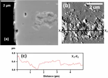
FIG. 11: Gold nickel bottom electrode after failure (1mA). (a) The SEM image and (b)
the AFM image of the micro-contact. (c) The height profile along X1-X2... 103
CHPATER 5 Comparison of Au and Au-Ni Alloys as Contact Materials for MEMS Switches... 107
FIG. 1: Au-Ni phase diagram, after Okamoto and Massalski... 112
FIG. 2: Configuration for the switching tests ... 115
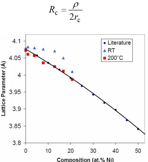
FIG. 3: Lattice parameter vs. nickel composition for films deposited at room temperature, and 200 °C, compared to bulk solid solution alloys ... 118
FIG: 4. XRD spectrum of the Au-Ni (20 at.% Ni) after rapid thermal annealing ... 118
FIG. 5: Calculated and measured contact resistance vs. nickel composition ... 121
FIG. 6: AFM images of pure Au sample (a) topographic (b) error (c) random line height profile... 122
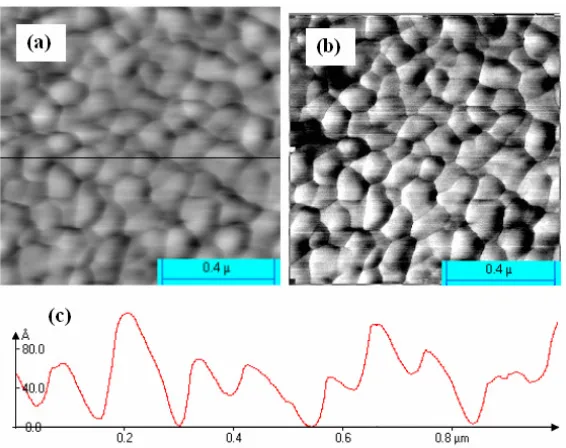
FIG. 7: AFM images of Au-Ni (20 at. % Ni, solid solution, as-deposited) sample (a) topographic (b) error (c) random line height profile... 123
FIG. 8: AFM images of Au-Ni (20 at.% Ni, two phase, after RTA) sample (a) topographic (b) error (c) random line height profile... 123
FIG. 9: Max. height difference in the random line-scan vs. Ni composition ... 124
FIG. 10: RMS roughness vs. nickel composition ... 124
FIG. 11: Micro-contacting tests on pure gold and Au-Ni alloys ... 125 FIG. 12: AFM images of the worn microcontacts on the Au cantilever, and the
cantilever in Au against Au test (b) The worn area on the pure Au bottom electrode corresponding to the microcontact shown in (a). (c) A worn Au microcontact in Au against Au-Ni (20 at.% Ni) test. (d) The worn area on the Au-Ni (20 at.% Ni) bottom electrode corresponding to the microcontact shown in (c) ... 128 FIG. 13: (a) XPS spectrum on Au-Ni (20 at.% Ni) solid solution sample. (b) XPS
FIG. 8: AFM images of the upper micro-contacts and bottom contact pads after 3600 cycles with AC 6V and 1mA ... 148 CHPATER 7 Resolving Transfer Directionality for Field Evaporation of Gold.... 157 FIG. 1: AFM images of the upper micro-contacts and bottom contact pads after 2000 cycles with DC 6V and 1mA ... 161 FIG. 2: Volume gain evolution with cycle number ... 161 FIG. 3: AFM images of the upper micro-contacts and bottom contact pads after 3600 cycles with AC 6V and 1mA ... 163 FIG. 4: Pt-Ti tip /Au substrate system: (a) AFM image of the contact area after the tip retracted with bias of -6 V; (b) a height profile along the line in (a); (c) AFM image of the contact area after the tip retracted with bias of +6 V retracted; (d) a height profile along the line in (c) ... 164 CHPATER 8 Brief Summary of Failure Modes for Gold-contact MEMS
1.1
Applications of Microelectromechanical (MEMS) Switches
Since the first MEMS switch was specially designed for microwave applications in the
early 90s [1], this technology has developed to the point that the devices are currently in
small-scale production. Typical MEMS switches are micron-scale switching devices.
Because of their low fabrication cost, low power consumption, wide operational band and
exceptional switching performance, MEMS switching technology holds great promise for
implementing agile radio frequency (RF) systems [2-10].
RF MEMS switches are currently being shipped or are in development for a very wide
spectrum of applications, from high-value niches such as satellites to mobile phones. Four
major application fields have been identified: test equipment, telecom infrastructures,
aerospace and defense and mobile phones. A projection for the growth of RF MEMS switch
market is shown in Figure 1 [11]. As can be seen in the figure, automated test equipment
(ATE) is the first, also the largest commercial application for RF switches. MEMS switches
can replace conventional relays with changing the system configurations. Major ATE
system suppliers such as Agilent are currently evaluating or have started implementation of
MEMS in their systems.
With respected to the telecom infrastructure application, MEMS switches are projected
to be implemented in wire-line telecom switching matrices early in 2008. The potential
applications for defense have historically driven the development of MEMS switches in US.
The volume application will be phased arrays antennas for communication and radars e.g.
for missiles, helicopters, aircrafts, drones, ships and so forth. Power amplifier (PA) and
capacitive-type switches) might beat CMOS switches for mobile phone applications in the
future.
FIG. 1: RF MEMS switch market forecast [11]
1.2 Issues with Metal Contact MEMS Switches
This thesis focuses on the issues that related to the degradation of metal contacts during
switch cycling operation since switch performance is directly tied to the reliability and
quality of the metal-contacts. Gold is often utilized as a contact material for metal-contact
MEMS switches due to its excellent electrical conductivity and corrosion resistance.
Gold-contact switches have been shown to achieve >109 cycles under appropriate operating
conditions (etc. low current, optimum contact force, dry nitrogen environment and ‘cold
switching’) [7, 12]. ‘Cold switching’ refers to switch operation under conditions in which
there is no field across the contacts as the switch opens or closes). However, there is a strong
operate. For example, Manufacturers of RF instrumentation equipment, i.e. network
analyzers, spectrum analyzers and oscilloscopes like Agilent, Rhode & Schwarz and
Tektronix are evaluating MEMS switches and would implement them in their RF
equipments. However, power handling issues must be solved prior to implementation in RF
instruments since hot switching is required, contrary to ATE. Here, ‘hot switching’ is defined
as switch cycling with a signal or potential difference across the electric contacts.
One approach to the problem is to investigate alternative contact materials, and a few
have been investigated [13-14]. However, there are some serious impediments to the broad
investigation of alternative contact materials. In general, convenient contact wear test
facilities do not closely mimic real contact switches. In particular, the tests have difficulty
duplicating the switch geometry, the contact geometry, and the contact force. Contact
geometry has a strong influence on the heat distribution across the contacts, and thus the
switch performance and failure mechanism [15-16].
One clear alternative is to test candidate materials on actual MEMS switches, and such
studies have been reported by researchers from universities and industry [7,17, 18, 19]. But
the approach has a serious difficulty: the switches are fabricated in Si foundries, and only a
limited range of materials may enter the fabrication facility. Secondly, the fabrication process
must be optimized for each material, and it may take many months to fabricate a set of
switches to test a single candidate contact material. Materials compatibility and process
integration issues must be addressed in advance for every material to be tested. These factors
have severely limited the range of contact materials that have been investigated for MEMS
must be more efficient while remaining representative of the typical device operation. In this
manner the material comparison and failure analysis data can be collected consistently and
efficiently.
Researchers have been investigating the degradation mechanisms of metal
micro-contacts in MEMS switches (reviewed in Chapter 2). However these highly-scattered failure
characterization results are contingent on different devices and test conditions therefore, are
not yet able to provide a systematic and quantitative overview of different degradation modes
in MEMS switches. A comprehensive understanding of the switch failure mechanisms has
not been achieved due to the absence of a systematic study of micro-contact degradation
modes and quantitative failure characterization, For example, failure analysis for hot
switching failure is particularly difficult because the degradation process can be complicated
by several possible modes such as arcing, transient current heating, static current heating and
mechanical wear. Additionally, dramatic failure observed under a non-arc condition has not
been clearly understood [20]. Research on contact degradation for MEMS switches has been
driven by the urge of developing high-reliable MEMS switches.
1.3 Brief Summary of Our Work
In our study, we designed the micro-contacting test facility that closely mimics the
typical MEMS operation and utilize this facility to efficiently evaluate different candidate
contact materials for MEMS switches. Using this facility, a binary gold alloy system- AuNi
was systematically studied (etc. chemical composition, micro-structure, surface conditions)
different test conditions (etc. high-voltage hot-switching, low voltage hot-switching, DC
switching, AC switching, mediate-force cold switching, low-force cold switching) has been
also systematically studied. Through our work, a better correlation between material
properties and micro-contacting performance is established and an improved understanding
of micro-contact degradation is achieved.
This document is comprised of eight chapters. Chapter one briefly introduces the topic
of RF MEMS metal contact switches and the focus of this thesis. Chapter two is a
comprehensive review of metal contact micro-switches and the related material topics.
Nano- and atomic scale material transfer theories are also reviewed because our work also
directly contributes to this general nano-science field. Chapter three summaries the
approaches we used to fabricate, characterize and test our candidate contact materials. The
design and construction of our unique test facility is described in details. Chapter four, five
present our work on gold and Au-Ni alloy system in format of research papers. Chapter six
addresses micro-contact degradation in MEMS switches under non-arc hot-switching
conditions. Chapter seven focuses on resolving the directionality of field evaporation for
gold. Chapter eight presents our work of cold switching tests. An overview of failure
mechanisms is also given in this chapter.
1.4 References
approach for microwave integrated circuits,” Microwave and Millimeter-Wave Monolithic
Circuits Symposium Digest. (Boston, MA) pp 27-30
[2] C. Bowick, RF Circuit Design. USA: Newnes – Elsevier Science, 1982
[3] D. L. Santos and J. Hector, “Microwave and mechanical considerations in the design of MEM
switches for aerospace applications, 1997
[4] E. R. Brown, “RF MEMS switches for reconfigurable integrated circuits,” IEEE Trans.
on MTT, 46 (11): 1868-1880, (November 1998)
[5] J. Chial. “MEMS for high-frequency applications,” Proc. 8th Annual Int. Symp. on Smart Mat.,
1-10 (March 2001)
[6] H. S. Newman. “RF MEMS switches and applications,” Proc. 40th Annual Int. Rel. Phy.
Symp., 111-115 (April 2002)
[7] G. M. Rebeiz, RF MEMS theory, design and technology, New Jersey: John Wiley & Sons,
Inc., 2003
[8] G. M. Rebeiz and J. B. Muldavin, “RF MEMS switches and switch circuits,” IEEE
Microwaves Magazine, 59-71 (December 2001)
[9] J. H. Schaffner, A. E. Schmitz, T. Hsu, D. T. Chang, R. Y. Loo and D. F. Sievenpiper, “Metal
contact RF MEMS switch elements for ultra wideband RF front-end systems,” Proc. Ultra
Wideband Sys. Tech., 32-36 (November 2003)
[10] V. K. Varadan, K. J. Vinoy and K. A. Jose, RF MEMS and their applications, Egland: John
Wiley & Sons, Ltd., 2003
[11] J. Bouchaud and B. Knoblich, “RF MEMS switches deliver on early promise,”
[12] A. S. Morris, S. Cunningham, D. Dereus and G. Schopfer, “High-performance integrated
RF-MEMS: Part 1 – the process,” Proceedings of 33rd European Microwave Conference, 2003,
pp. 21-24
[13] J. Schimkat, “ Contact materials for microrelays,” in 11th Proc. MEMS’ 98 Workshop,
1998, pp. 190-194
[14] R. A. Coutu, Ph.D. Dissertation: Electrostatic Radio Frequency (RF) MicroElectroMechnical
Systems (MEMS) Switches with Metal Alloy Electric Contacts Air Force Institute of
Technology. 2004.
[15] L. Chen, “Contact evolution in micromechanical switches,” in World Tribology Congress, Washington D. C., U.S.A. 2005
[16] D. Hyman and M. Mehregany, “ Contact physics of gold microcontacts for MEMS
switches,” IEEE Trans. Comp. Packag. Tech., vol. 22, pp. 357-364, 1999
[17] K. Hiltmann, A. Schumacher, K. Guttmann, E. Lemp, H. Sandmaier, W. Lang, “New
micro-machined membrane switches in silicon technology,” 47th IEEE Holm
Conference on Electrical Contacts pp. 190-194, 2001
[18] K. Hiltmann, W. Keller and W. Lang, ”Micromachined switches for low electric
loads,” Sensors and Actuators A74 203-206, 1999
[19] S. Majumder et al, “MEMS switches,” IEEE Intrumentation & Measurement Magazine6(1)
12, 2003
[20] E. J. J. Kruglick and K. S. J. Pister, “Lateral MEMS microcontact consideration,”, J.
CHAPTER 2 LITERATURE REVIEW
2.1 Desires for MEMS Switch Technology
In modern microelectronics, to switch between the electrical ‘on’ and ‘off’ states, solid
state devices (etc. transistors and diodes) utilize voltage potential to modulate the carrier
concentration in semiconductors. Conductivity modulation through the same channel
(normally crystalline silicon material) poses some performance limitations on signal insertion
loss, cut-off frequency and isolation for this technology. MEMS switch technology was
developed with the intention to achieve improved device performance beyond these
limitations by adding micro-mechanical movement into microelectronics. In MEMS devices,
electrical ‘on’ and ‘off’ states are mechanically switched.
Among all the actuation modes, electrostatic actuation is the most prevalent technique
because of the following reasons: there is no DC current involved in the actuation process,
therefore virtually no DC power is consumed; the actuation electrodes are normally
lithographically defined using standard micro-fabrication procedures, therefore they have
small size and are compatible with IC fabrication; the switching speed ranges from 1 to 200
µs and is much higher than thermal or magneto-static actuation. Table 1.1 shows a
performance comparison of FETs, PIN Diode and RF Electrostatic switches. MEMS
switches outperform semiconductor switches in the areas of power consumption, serial
resistance (on-state resistance), cut-off frequency, isolation and signal insertion loss. For
metal-contact MEMS switches, a high-quality, reliable metal-metal contact is directly tied to
Table 1: Performance comparison of FETs, PIN Diode and RF MEMS Electrostatic Switches [6]
Comparing to macro-size electromechanical switches, MEMS switches share the same
advantages of having a low-resistance metal contact and high open-contact isolation. But
they can be more easily implemented with planar RF circuitry because of their planar
fabrication processes. Another drawback of implementing macro-size switches is that they
have relatively slow switching speeds (2- 15 ms), which is a few orders of magnitude higher
than MEMS switches.
2.2 Categorization and fabrication of RF MEMS switches
There are two classes of RF MEMS switches: capacitive switches and metal-contact
switches. Capacitive switches are typically used as shunt switches while metal-contact
switches are used as series switches in RF circuits. Shunt switch refers to the switch placed
transmission lines to switch the signal path. For metal-contact switches, the signal is
conducted through metal contacts and the applicable signal frequency ranges from DC to 60
GHz. For capacitive switches, the contact is made between the metal and dielectric material.
This type of switch utilizes the capacitance modulation to vary signal impedance during
switching operation. In the shunt configuration the switch-open state passes RF signal while
the switch-close state shorts the signal to ground. Therefore, its applicable signal frequency
ranges from 6 GHz to 120 GHz. Our work focuses on metal contact MEMS switches.
RF MEMS switches are typically fabricated using low-temperature processes and are
therefore compatible with post-CMOS, SiGe and GaAs integration. Most of them are surface
micro-machined and can even be integrated on glass, quartz and polished ceramic substrates.
Motorola has demonstrated an integrated RF MEMS switch chip with high voltage charge
pump and control logic CMOS in a single package. Extensive use of the this type of
integration is expected to meet the future demand of high frequency wireless applications
because it can provide the faster switching speed, 3 volt compatibility and reliability [1].
Integration of MEMS switches with GaAs FETs (amplifiers) has also been demonstrated by a
few groups such as NTT DoCoMo Inc. and Rockwell scientific [2, 3]. A dual band amplifier
net-work with such integration is shown in figure 1 [2]. Nowadays, the manufacture of RF
MEMS switches has been mainly carried in highly specialized commercial foundries because
of the high diversified fabrication processes. Figure 2 shows the top ten MEMS foundries
FIG. 1: Schematic of the dual-band amplifier [2].
FIG. 2: MEMS top 10 foundries [92].
Figure 3 shows an example of electrostatic, metal-contact MEMS switch [4]. The switch
is actuated by the electrostatic force between the two metal-pad electrodes. In order to
generate a force for switch actuation, these two metal-pads need to be charged by a DC
value, the upper micro-contacts are lowered by the electrostatic force to contact with the
bottom contacts, then signals can be transmitted through. When the metal-pad electrodes are
discharged, the switch is opened and the two transmission lines are disconnected. Several
important aspects of metal contact MEMS switches are review as following.
FIG. 3: A schematic of the wiSpry metal contact MEMS switch [4].
2.3
Actuation Mechanics (Electrostatic Switches)
Contact mechanics describe how switch is actuated. For electrostatic switches, the
actuation process particularly includes the following steps.
Step 1: Charging of the metal electrode pads located on the upper MEMS cantilever and the
bottom substrate
Step 2: Generated electrostatic force brings the upper MEMS cantilever down to a point that
the upper micro-contacts make stable contact with the bottom contacts.
Step 3: The two metal electrode pads are discharged; without the electrostatic force,
restoring force of the upper MEMS cantilever raises the micro-contacts again.
capacitor models and contact force calculations needs to be carefully reviewed.
2.3.1 Cantilever Beam
Since the actuation is mainly realized by the deflection of the upper MEMS cantilever, we
assume that the cantilever behaves like a beam, as illustrated by Figure 4. The fixed end
is at x = 0, a free end at x = l, and an intermediately placed external load (Fa) is located at x =
a as point source [5, 6].
According to Shigley et al. [5], the maximum beam tip deflection with the intermediately
placed load is:
(
3
)
6
2
a
l
EI
a
F
d
z
a
−
=
(1)FIG. 4: Cantilever beam model with a fixed end at (x=0), a free end at (x=l), and an intermediately placed external load, Fa.
where, d is the maximum cantilever beam tip deflection, Fa is the externally applied load, a is
12
3
w
t
I
z=
(2)where, t is the beam’s thickness and w is the beam width.
In equation 1, all the inputs are determined by the beam properties except the external
load (Fa) and the maximum cantilever beam tip deflection (d). Actually, if the defection is
relatively small, the relation of the force and the defection obeys Hookes’ law [5, 7].
F
=
kd
(3)The spring constant k for the beam shown in Figure 5 can be found by solving equation 1
for the applied force and substituting Equation 1 for area moment of inertia. It can be
expressed as:
)
3
(
2
2 3a
l
a
w
Et
k
−
=
(4)In our work, this beam model is used to estimate the contact force for the MEMS dynamic
switching tests (chapter 4). The calibrated contact force is about 150 µN /micro-contact (300
µN in total). An improved beam model that accounts for anchor can be found in elsewhere
[8]. Parallel plate capacitor models are presented next to quantitatively address the question:
“How much force can be generated by charging up the capacitor?”
2.3.2 Parallel Plate Capacitor Models
For electrostatic MEMS switches, the actuation force is generated by charging up the
metal electrode pads on both the switch’s upper cantilever and bottom part. The cantilever
and the bottom electrode therefore can be modeled as a parallel plate capacitor. The charge
Q
=
CV
(5)where, Q is the charge, C is the capacitance, and V is the voltage across the parallel plate
capacitor. The capacitance of a parallel plate capacitor is given by
g
A
C
=
ε
0(6)
where, ε0 is the permittivity of free space, A is the surface area of the parallel plate, and g is
the distance or gap between the plates. The work required to charge the capacitor from 0 to Q
coulombs is give by:
C
Q
dq
C
q
W
Q2
2 0=
=
∫
(7)where, W is the work, and q is the integration variable that represents the charge on the
capacitance [9]. Substituting in Equation 5 for charge and Equation 6 for capacitance into
Equation 7 results in:
g
AV
W
2
2 0ε
=
(8)Since this work is used to charge the capacitance, it finally converted to the potential
energy (U) stored in the parallel plate capacitor. This potential energy causes the actuation,
therefore, triggers the change of gap distance. The varying electrostatic force (Fe) in the
actuation process can be derived from the potential energy (U) [9, 10].
dg
dU
If we substitute Equation 8 into Equation 9, the electrostatic force can be expressed by the actuation voltage: 2 2 0
2
g
AV
F
e=
ε
(10)First-order fringing field correction has been used to account for non-parallel electric fields
developed outside of the confines of the parallel plate capacitor. With this correction, the
electrostatic force is expressed by Equation 11.
[
1
0
.
42
]
2
0 2 2 0w
g
g
AV
F
e=
ε
+
(11)For an electrostatic MEMS switch, the electrostatic force Fe equals the cantilever
restoring force Fs when the cantilever is in equilibrium. Therefore, Equation 3 can be
substituted into Equation 10 resulting:
A
kd
d
g
V
0 02
)
(
ε
−
=
(12)The pull-in deflection distance (dpi) can be defined as the deflection when the electrostatic
force overcomes the beam’s mechanical restoring force and the upper micro-contacts are
brought down into contact with the bottom contacts. Taking the derivative of the voltage V
with respect to the deflection d yields the pull-in defection dpi.
2
(
)
2
(
2
1
)
1
0
3
0
g
d
pi=
⇒
(13)Substituting Equation 13 back into Equation 12 yields pull-in voltage Vpi.
A
kd
d
g
V
pi pi pi0 0
2
)
(
ε
−
=
g
k
A
0 3 027
8
ε
=
(14)If first-order fringing field correction is taken into consideration, the pull-in voltage can be
expressed by Equation 15.
)
42
.
0
1
(
27
8
0 0 3 0w
g
A
k
g
+
ε
(15)Implementation of these first-order parallel plate capacitor model and simple beam
deflection models have been justified by the MEMS design community [6, 11].
2.3.3 Contact Force
In order to achieve an acceptable low contact resistance, certain clean metal contact area
is needed. This contact area forms as a result of contact material deformation. Contact force
is used to induce this material deformation. If the actual contact force is un-necessarily large,
it could cause excessive contact wear, thus fail the device in a short term. On the other hand,
if the actual contact force is too small, the resulted contact material deformation may not be
and accurately predict contact force in MEMS switch is of great important for the success of
electrostatic MEMS switch design.
For electrostatic MEMS switches, the contact force is relatively low. The values range
from tens of µN’s up to a few mN’s. This contact force is mainly determined by the
mechanical switch design.
As has been mentioned in the section 2.3.2 that, the upper micro-contacts can brought
down into contact with the bottom contacts by applying a pull-in voltage Vpi. However, in
this case, the resulted contact material deformation usually is too small to generate a low
contact resistance [6]. The solution is to increase the actuation voltage well above the pull-in
voltage. Thus the upper cantilever begins to bend after pull-in so that additional force is
supplied to the contact area. Friction between the contacts caused by cantilever bending may
also help to mechanically wipe contaminant films from the contact area [11].
FIG. 5: The additional cantilever deflection after pull-in.
After pull-in, the upper MEMS cantilever can be modeled as a beam with a fixed end at
micro-x =a, and a supporting force Fc at x = l (this is the contact force). Detailed calculation and
derivation can be found in the mechanical text book [5]. Only the final form of contact force
is given here.
(
3
)
)
(
4
2 0 3 2 20
l
a
d
g
l
a
AV
F
c−
−
=
ε
(16)Obviously, this simple, static model does not account for beam tip deflection (no restoring
force has been deducted in the calculation), nor material deformation in the contact area after
switch closure. Nevertheless, this model has been proven to be valid until the over-driven
cantilever collapses onto the bottom electrodes. It is used to analytically determine switch
contact force. Recently, Coutu et al. have introduced a more detailed contact force model in
which contact material deformation and beam deflection are considered [11, 12].
Beam collapse voltage also needs to be estimated to avoid device failure. This value can
be calculated following the same procedure of calculating the beam’s pull-in voltage
(Equation 12). It should be noticed that the spring constant k has been changed to k’ after
pull-in. Also the new initial gap under the pulled-in beam is defined as g1. The resulted
collapse voltage is shown in Equation 17.
A
d
k
g
g
V
cpi c0 ' 1
2
)
(
ε
−
=
(17)When the driving voltage exceeds this value, a physical contact is established between
2.4 Contact Mechanics
Besides contact force, contact resistance is determined by material properties of the
contact surfaces such as contact geometry, surface topology, electrical resistivity and
micro-hardness. In this section, contact area models, material deformation models, contact
resistance and electron transport models are reviewed so that reasonable estimations of
contact resistance can be made for electrostatic MEMS switches.
It has been well know that surfaces are rough at microscopic scale. It makes calculation of
contact area difficult. Early efforts have involved implementation of Hertzian theory of
contact to simulate the contact deformation. Holm later introduced the idea that although the
overall stresses are in the elastic regime the local stresses at contact spots may be much
higher so that local plastic deformation could occur. This theory has been widely accepted by
the research community of electric contact [13]. In 1966, Greenwood and Williamson
published a new contact theory which is more closely related to real surfaces than the earlier
ones. They showed how contact deformation depends on the topography of the surface, and
established the criterion for distinguishing surfaces that deform elastically from those deform
plastically. They found that contact between surfaces is frequently plastic, as usually
assumed, but surfaces which deforms elastically are by no means uncommon in engineering
practice. [14]. Their work forms the base for multiple asperity model. McCool’s studies of
anisotropic roughness surface with randomly distributed asperities showed good agreement
with Greenwood and Williamson’s model [16]. In practice, Hertz’s model is used for classic
elastic deformation while Abbott and Fireston’s model is used for plastic deformation with
case of elastic-plastic deformation, Chang, Etison & Bogy (CEB) model may be considered
[17].
In a simplified single effective asperity model, multiple micro-contact sites are converted
into one single effective contact site. The effective contact area is defined as the sum of all
the individual contact areas [22]. Calculated resistances from this model are slightly higher
than those from the multiple asperity model [23].
In MEMS switch fabrication, planar thin film deposition techniques have been used to
minimize the roughness. However, those surfaces of metal micro-contacts are still quite
rough when examined at the scale of nano-meters. Therefore, these earlier models should still
be applicable. Particularly, much work has been done in the past twenty years with respect to
modeling of micro-contact resistance. Majumder et al. modeled the actual micro-switches
with a comprehensive consideration of ballistic and diffusive electron transport [18] and
various types of contact material deformation [19]. Kogut and Komvopulos developed an
electrical contact resistance (ECR) model for conductive rough surfaces with and without
thin insulating film separation based on the real contact area [20, 21]. Recently, Coutu et al.
have updated micro-contact resistance model to account for the surface asperity interaction
that occurs in sputtered contact thin films [24]. Although these models, in some cases, has
provided some fairly good prediction of the real contact resistance, exact match between
simulation and experimental results has not been achieved due to several reasons: firstly, it is
difficult to quarantine the pure single-pair contact resistance from resistance measurement of
a MEMS switch chip. For example, resistances of other resistive components such as
conditions (etc. adsorbed films) may cause measurement variation for each switch; thirdly,
real surface topology of the devices normally was not input into the resistance simulation
which makes the simulated results less accurate. In this study, our four-point probes in-situ
contact resistance measurement set-up gets direct access to the micro-contact pairs because
of our unique test design (details in chapter 3 and chapter 4). Efficient resistance
measurement and good access to both contact surfaces enable us to get good repeatability on
experimental results.
Next, different regions of contact material deformation are reviewed in detail because
simple calculations based on these fundamental contact physics actually give good prediction
of device contact resistance.
2.4.1 Elastic Deformation
Under elastic deformation, the contact area and contact force in single asperity model can
be expressed by Equation 18 and Equation 19
A
=
π
R
α
(18)where A is contact area, R is asperity peak radius of curvature, and α is asperity vertical
deformation.
F
cE
α
R
α
'3
4
=
(19)Where Fc is the normal contact force and E’ is the Hertzian modulus which can be derived
2 2 2 1 2 1
1
1
'
1
E
E
E
ν
ν
−
+
−
=
(20)where, E1 is the elastic modulus for contact one, v1 is Poisson’s ratio for contact one, E2 is the
elastic modulus for contact two, and v2 is Poisson’s ratio for contact two.
Assume it is a circular area, the effective contact radius can be derived based on Equation
18 and Equation 19.
3
'
4
3
E
R
F
r
=
c(21)
This effective radius is one of the important parameters that determine the switch contact
resistance in the case of pure elastic deformation.
2.4.2 Plastic Deformation
Under plastic deformation, the contact area and contact force in single asperity model can
be expressed by Equation 22 and Equation 23
A
=
2
π
R
α
(22)
F
c=
HA
(23)where, H is the hardness and A is the contact area [25, 70]. Therefore the effective contact
π
H
F
r
=
c(24)
In MEMS community, this simple expression of effective contact resistance has been
frequently used to calculate the device contact resistance.
2.4.3 Elastic-Plastic Deformation (The CEB Model)
Chang, Etison & Bogy (CEB) model accounts for the transition region between elastic
deformation and plastic deformation. It is a description of a more complicated deformation
when parts of the contact area are plastically deformed but encased by elastically deformed
material [26].
Contact area is calculated based on conservation of volume of the deformed asperity and
the resulted expression is shown by Equation 25, where R denotes the end radius of the
curvature of the asperity, αc is the critical vertical deformation, where plastic yielding is
assumed to occur. This parameter is defined by Equation 26, where KH is the hardness
coefficient which is assumed to be equal to 0.6 at the onset of plastic deformation [17].
(
2
)
α
α
α
π
R
cA
=
−
(25)2
)
2'
3
.
0
(
)
'
2
(
E
H
R
E
H
K
R
H cπ
π
α
=
=
(26)The contact force on this asperity and the effective contact radius can be calculated
respectively using Equation 27 and Equation 28:
r
=
R
α
(
2
−
α
α
c)
α
>α
c (28)Majumder et al. applied this model to simulate the multiple-asperity rough surface [43].
Later on, more efforts were made by Kogut et al. on improving the elastic-plastic modeling
[27, 28].
2.5 Contact Resistance Modeling
With no contamination film presented in the contact area, contact resistance is generally
equivalent to the constriction resistance of the connection between two conductors. It is
called “restriction” because electrical current can only flow through metal-metal contact
spots during switch closure. For micro-contacts in MEMS switches, real metal-metal contact
sizes may affect the way electrons are transported through these constricted contact spots.
And different electron transport mechanisms may result in different forms of constriction
resistance.
There are three types of electron transport mechanisms that could occur in MEMS
switches: diffusive transport, ballistic transport and quasi-ballistic transport [29]. The
ballistic transport occurs when the electron mean free path le is larger than the effective
contact radius r (le > r); the quasi-ballistic transport occurs when the electron mean free path
is comparable to the effective contact radius (le ~ r); diffusion occurs when the electron mean
free path is much smaller than the effective contact radius (le << r). The distinctively
FIG. 6: Schematic illustration of (a) diffusive and (b) ballistic electron transport through a constricted conductor [2].
2.5.1 Diffusive Electron Transport
For diffusive transport, well-established Maxwell spreading resistance equation can be
used to calculate the contact resistance [13].
r
R
c2
ρ
=
(29)Where, ρ is electrical resistivity.
For elastic deformation, substitute Equation 21 into Equation 29, contact resistance RcDE
(DE denotes diffusive transport and elastic deformation) can be expressed in terms of
asperity properties and contact force.
3
3
'
4
2
F
R
E
R
c cDE
ρ
=
(30)Where, E’ again is the Hertzian Modulus which is dependent on the elastic modulus of the
For plastic deformation, substitute Equation 24 into Equation 29, contact resistance RcDP
(DE denotes diffusive transport and plastic deformation) also can be expressed in terms of
asperity properties and contact force.
c cDP
F
H
R
ρ
π
2
=
(31)For metal contact MEMS switches with a contact force above 100 µN, it is generally
believed that plastic deformation occurs during making contact [6]. Therefore this simple
equation has been widely used to predict switch contact resistance.
2.5.2 Ballistic and Quasi-ballistic Electron Transport
For ballistic transport, Sharvin resistance is the major contributor to the contact resistance
[19, 30]. The form of Sharvin resistance is given in Equation 32.
r
K
R
sπ
ρ
3
4
=
(32)where, K is the Knudsen number that can be expressed by Equation 33.
r
l
K
=
e(33)
An interpolation between the ballistic and diffusive electron transport regions can be made
using the Gamma function Γ (K) [31]. A well behaved form of Gamma function is given in
Equation 34 [32].
(
K
)
2
e
Kxsin
c
(
x
)
dx
0∫
∞ −≈
Γ
A plot of “Gamma function vs. Knudsen number” is shown in FIG. 7.
FIG. 7: Plot of Mikrajuddin et al.’s plot of ‘Gamma function vs. Knudsen Number [32].
A form complete form of contact resistance is derived by Wexler [31] and is shown in
Equation 35.
R
w=
R
s+
Γ
(
K
)
R
c (35)In our work, contact resistance modeling approach is contingent on two assessments. One
is to check whether the effective contact radius is much larger than the electron mean free
path so that electron transport mechanism can be determined. In our test, the estimated
effective contact radius is more than 100 nm and the mean free path of electrons in gold is
only ~ 36 nm. Therefore, diffusive transport model was used for the resistance calculation.
The second is to check whether the plastic yielding point is reached so that deformation
model can be properly assessed. In our case, plastic deformation is assumed based on the
contact force and critical yielding estimation. It turns out that calculation based on these
2.6 Contact Metal Alloys
2.6.1 Actuation Voltage Issue.
As for electrostatic MEMS switches, the actuation voltage is normally in range of tens of
volts which is an order of magnitude than typical RF circuit voltage. The solution is to
convert low voltage to the required actuation voltage using a voltage charge pump and
integrate it with MEMS switches. For example, Motorola adopted this configuration for its
RF MEMS chips [1]. Discrete voltage charge pump has also been commercialized [33].
Innovative electrostatic mechanical switch designs have also been studied extensively to
lower the actuation voltage [6, 34-41]. A trade-off between beam spring constant and switch
actuation voltage is discovered in the work: the actuation voltage decreases with a decreasing
beam spring constant. The problem is that by lowering the beam spring constant, the switch
restoring force is also lowered assuming the deflection of the beam is the same (which is
normally the case). As a result, it increases the risk of stiction failure. Up to now, only
limited success has been achieved using mechanical design solution with respect to this
problem [42]. This failure mode is also directly related to the high adhesion energy between
two pure gold surfaces and will be discussed later.
2.6.2Material Approach
Another approach to minimize the stiction and enhance the wear resistance is to use
different metals or alloys as the switch contact materials. Schimkat used rivets made of pure
Au, Au-Ni (5 %) alloy and Rh to test their potentials as the contact materials for
micro-switches. [43] Technically, the samples are still macro-size although the contact force has
hot switching cycles with 50 VDC and 50 mA to clean the contamination layer on the metal
surfaces), contact resistance of ~ 10 mΩ was achieved under a force load of ~100 µN.
However, much higher contact resistances have been reported for actual micro-switches
[44-48]. Schimkat also found that much less surface adhesion was generated if harder metals
(Au-Ni (5 %) and Rh) were used although a larger contact force was needed (to achieve a
low, stable resistance).
Coutu have investigated using different gold alloys (Au, AuPt, AuPd, AuAg, AuPtCu
etc.) as the contact materials of the actual MEMS switches [48]. The alloy system selection
was based on the rule of avoiding two-phase micro-structure although the reason of using this
rule has not been well established. Cotu’s work focuses on characterization of the basic
material properties such as hardness, electrical resistivity and element composition. His
predicted contact resistances (based on the material properties and contact force) fall in the
range of between 0.20 ~ 0.6 Ohm. Mostly likely due to the contamination films, his
measured contact resistance was normally much higher than the predicted values with the
only exception of the AuPtCu alloy (simulated value: 0.2 Ohm, measured value: 0.33) [48].
Obviously, in order to understand the material-related micro-contact performance, surface
conditions and material micro-structures needs be carefully addressed.
Majumder et al. and Duffy et al. have utilized “platinum group” and platinum contact
metals respectively to reduce the stiction, thus to extend the switch lifetime [49, 50] In
Duffy’s case, contact resistance below 1 Ohm can be achieved using an actuation voltage 45
V higher than the actuation threshold voltage (~ 35 V). In Majumder’s case, the single
contact resistance below 1 Ohm. So generally there is a trade-off between contact resistance
and wear resistance / low adhesion. To minimize the contact resistance while dramatically
increasing the wear resistance is always the goal of the material scientists in this field.
McGruer et al. utilized a MEMS switching test simulator to examine the candidate
contact materials [51]. It was found that Pt, Ru, Rh and Au-Ru alloys not only yield much
higher contact resistance, but also fail earlier due to a quick rise of contact resistance during
the test in ambient air. Material-dependent adsorption of contaminations from air was
considered as an issue for Pt, Ru and Rh.
As a summary of the above work, we can see that hardened gold alloys have been used
alternative contact materials for MEMS switches hoping to reduce contact surface adhesion
and enhance the wear resistance. These materials have demonstrated some different
micro-contacting performance in terms of contact resistance and switch cycling lifetime. For
example, Coutu et al. pointed out that binary / ternary gold alloys may increase the switch
lifetime at some cost of contact resistance. However, in general, material scientists haven’t
been able to address the micro-contacting performance based on the specific material
properties such as surface topology, crystallographic features (structure),
micro-hardness and electrical resistivity. The correction between material properties and contacting
performance has not been established. In addition, no binary or ternary gold-based alloy
system has been systematically investigated regarding its potential use as MEMS contact
materials. It is the author’s opinion that by systematically studying one gold-based alloy
system, one can more easily differentiate the effects from different material properties on
material system for this purpose, one needs to understand how material selection and
preparation could affect those critical material properties (etc. micro-hardness, surface
topology, electrical resistivity). Material strengthening theory in the following sections serves
as the background knowledge for our purpose.
2.6.3 Solid Solution Hardening
Material can be hardened by the addition of small quantities of an alloying element. For
solid solution hardening, the increase of the hardness is not due to any change in
microstructure of the alloy. The microstructure remains the same. It is the lattice strains that
cause the strengthening and hardening of the alloy. The lattice strains are introduced into the
material by those added solute atoms [52]. The solute may incorporate into the solvent
crystal lattice substitutionally, by replacing a solvent particle in the lattice or, interstitially, by
fitting into the space between solvent particles. Both of these types of solid solution affect the
properties of the material by distorting the crystal lattice and disrupting the physical and
electrical homogeneity of the solvent material.
2.6.4 Second Phase Hardening
Second phase hardening (also called dispersion hardening, precipitation hardening or age
hardening) is achieved by introducing precipitations into the host atom matrix. A heating
treatment technique is normally used induce the precipitations depending on the changes in
solid solubility with temperature of specific material systems. Fine precipitated second-phase
particles impede the movement of dislocations or defects in the crystal’s lattice. Since
dislocations are often the dominant carriers of plasticity, by impeding the dislocations, one
During the heating treatment, the micro-structure is changed which may cause changes of
local chemical composition, hardness and electrical properties. Next, Au-Ni material system
is investigated as a possible choice of the metal contact material for MEMS switch
application.
2.6.5 An Example: Au-Ni System
Figure 8 shows the equilibrium binary alloy phase diagram for gold-nickel alloy [54]. Our
interested region is located in low-nickel composition side (≤ 20 Ni at. %). The intention is to
minimize the electrical resistivity while still achieving some hardening effect. As can be
observed in Figure 5, both metals are FCC structures, and exist as a two phase mixture at
relatively low temperature under equilibrium conditions. However, a metastable single phase
alloy may also be produced under the low processing temperatures utilized for the film
deposition. Thus, a comparison of the metastable solid-solutions and the two-phase mixtures
of the same overall composition can be undertaken, so that both microstructure effects and
composition effects can be examined. Schimkat tested gold-nickel (Au- (5%) Ni)
macro-switch electric contact under low contact force (100 – 600 µN) conditions [43]. He found that
Au-Ni alloy contacts yield much lower adhesion than pure gold contacts. Relatively low
force stable contact and reliable re-opening were also achieved in this report. However, in his
study, only samples with one composition (5 % Ni) were investigated, using bulky samples
(rivets) as test components. Therefore, to systematically explore this interesting material
system, we feel compelled to undertaken a study of a wider range of alloy compositions,
FIG.8: Au-Ni phase diagram, after Okamoto and Massalski [54].
2.7 Contact Degradation Mechanisms
2.7.1 Contact Wear
A recent industrial survey has shown that stiction and wear are the top two failure
modes for MEMS actuators [55]. Wear is the erosion of material from a solid surface by the
action of another solid. For low-power cold switched micro-switches, mechanical wear such
as pitting and hardening of the metal contact area is considered as the dominant failure
mechanisms [6]. Pitting and hardening occur as a result of the repeat impaction between two
metal contacts. And this may reduce the contact area and therefore increase the contact
resistance of the switch. At a high-power level, the switch lifetime is dramatically reduced.
For example, many metal contact MEMS switches have achieved multi-billion cycles under
considered as the major failing factor in this situation. Since electrostatic micro-switches
normally generate small forces ranging from 10s µN to ~1 mN, the resulted effective contact
radius is only on the order of ~ 100 nm. Under such circumstances, even a small current (ex.
~ 100 mA) flowing through this constricted area could yield high current density and rapidly
heat up the micro-contacts causing progressive, non-recoverable material deformation and
even melting.
Stiction failure in metal contact switches is a result of the surface adhesion between two
metal micro-contacts. It occurs when the adhesive bonding force is greater than the
mechanical separation force. High surface adhesion could also induce surface damage and
material transfer which can be defined as adhesive wear [56, 57].
2.7.2 Arcing
Metal phase arc has been considered as a possible failure mechanism for hot-switched
metal contact MEMS switches [6, 58]. However, this statement has not been justified by the
non-arc test conditions [58]. And up to now, no experimental evidence of electric arc (ex.
in-situ record of I-V transients) in MEMS switches has been reported. One purpose of our work
is to investigate the non-arc hot-switching failure mechanisms for metal contact MEMS
switches. A review of related previous work is presented below.
Research of arcing can be traced back to the development of electric relays and switches
in the early 20th century. Most commonly, it relates to an ‘electric arc’ between the electrical
contacts in the devices. In medium- and high- power electrical circuits, contact metal can be
vaporized by an arc at high current (thousands of amperes). In addition to the vaporization,
![FIG. 1: RF MEMS switch market forecast [11]](https://thumb-us.123doks.com/thumbv2/123dok_us/1303490.1162949/20.595.131.435.160.363/fig-rf-mems-switch-market-forecast.webp)
![Table 1: Performance comparison of FETs, PIN Diode and RF MEMS Electrostatic Switches [6]](https://thumb-us.123doks.com/thumbv2/123dok_us/1303490.1162949/28.595.97.491.136.337/table-performance-comparison-fets-diode-mems-electrostatic-switches.webp)


![FIG. 1: Au-Ni phase diagram, after Okamoto and Massalski [16].](https://thumb-us.123doks.com/thumbv2/123dok_us/1303490.1162949/129.595.157.456.103.321/fig-au-ni-phase-diagram-after-okamoto-massalski.webp)