SHDSL ATM DSU
User Manual
Any brand names and product names included in this manual are trademarks, registered trademarks, or trade names of their respective holders.
To the Holder of the Manual
The contents of this manual are current as of the date of publication. ADTRAN reserves the right to change the contents without prior notice.
In no event will ADTRAN be liable for any special, incidental, or consequential damages or for commercial losses even if ADTRAN has been advised thereof as a result of issue of this publication.
901 Explorer Boulevard P.O. Box 140000 Huntsville, AL 35814-4000
Phone: (256) 963-8000 ©2002 ADTRAN, Inc. All Rights Reserved.
Safety Instructions
When using your telephone equipment, please follow these basic safety precautions to reduce the risk of fire, electrical shock, or personal injury:
1. Do not use this product near water, such as a bathtub, wash bowl, kitchen sink, laundry tub, in a wet basement, or near a swimming pool.
2. Avoid using a telephone (other than a cordless-type) during an electrical storm. There is a remote risk of shock from lightning.
3. Do not use the telephone to report a gas leak in the vicinity of the leak.
4. Use only the power cord, power supply, and/or batteries indicated in the manual. Do not dispose of batteries in a fire. They may explode. Check with local codes for special disposal instructions.
Save These Important Safety Instructions
Cautions signify information that could prevent service interruption.
• An affidavit is required to be given to the telephone company whenever digital terminal equipment without encoded analog content and billing protection is used to transmit digital signals containing encoded analog content which are intended for eventual conversion into voiceband analog signals and transmitted on the network.
• The affidavit shall affirm that either no encoded analog content or billing information is being transmitted or that the output of the device meets Part 68 encoded analog content or billing protection specifications.
For the work to be performed in the certified territory of ___________________ (telco name) State of ________________
County of ________________
I, _______________________ (name), ____________________________________ (business address), ____________________ (telephone number) being duly sworn, state:
I have responsibility for the operation and maintenance of the terminal equipment to be connected to 1.544 Mbps and/or ________ subrate digital services. The terminal equipment to be connected complies with Part 68 of the FCC rules except for the encoded analog content and billing protection specifications. With respect to encoded analog content and billing protection:
( ) I attest that all operations associated with the establishment, maintenance, and adjustment of the digital CPE with respect to analog content and encoded billing protection information continuously complies with Part 68 of the FCC Rules and Regulations.
( ) The digital CPE does not transmit digital signals containing encoded analog content or billing information which is intended to be decoded within the telecommunications network.
( ) The encoded analog content and billing protection is factory set and is not under the control of the customer.
I attest that the operator(s)/maintainer(s) of the digital CPE responsible for the establishment, maintenance, and adjustment of the encoded analog content and billing information has (have) been trained to perform these functions by successfully having completed one of the following (check appropriate blocks):
( ) A. A training course provided by the manufacturer/grantee of the equipment used to encode analog signals; or
( ) B. A training course provided by the customer or authorized representative, using training materials and instructions provided by the manufacturer/grantee of the equipment used to encode analog signals; or
requested.
_________________________________Signature _________________________________Title _________________________________ Date Transcribed and sworn to before me
This ________ day of _______________, _______
_________________________________ Notary Public
My commission expires:
1. This equipment complies with Part 68 of FCC rules. On the back of the equipment housing is a label showing the FCC registration number and ringer equivalence number (REN). If requested, provide this information to the telephone company.
2. If this equipment causes harm to the telephone network, the telephone company may temporarily discontinue service. If possible, advance notification is given; otherwise, notification is given as soon as possible. The telephone company will advise the customer of the right to file a complaint with the FCC.
3. The telephone company may make changes in its facilities, equipment, operations, or procedures that could affect the proper operation of this equipment. Advance notification and the opportunity to maintain uninterrupted service are given.
4. If experiencing difficulty with this equipment, please contact ADTRAN for repair and warranty information. The telephone company may require this equipment to be disconnected from the network until the problem is corrected or it is certain the equipment is not malfunctioning. 5. This unit contains no user-serviceable parts.
6. An FCC compliant telephone cord with a modular plug is provided with this equipment. This equipment is designed to be connected to the telephone network or premises wiring using an FCC compatible modular jack, which is Part 68 compliant.
7. The following information may be required when applying to the local telephone company for a dial-up line for the V.34 modem:
8. The REN is useful in determining the quantity of devices you may connect to your telephone line and still have all of those devices ring when your number is called. In most areas, the sum of the RENs of all devices should not exceed five. To be certain of the number of devices you may connect to your line as determined by the REN, call your telephone company to determine the maximum REN for your calling area.
9. This equipment may not be used on coin service provided by the telephone company. Connection to party lines is subject to state tariffs. Contact your state public utility commission or corporation commission for information.
Service Type REN FIC USOC
This equipment has been tested and found to comply with the limits for a Class A digital device, pursuant to Part 15 of the FCC Rules. These limits are designed to provide reasonable protection against harmful interference when the equipment is operated in a commercial environment. This equipment generates, uses, and can radiate radio frequency energy and, if not installed and used in accordance with the
instruction manual, may cause harmful interference to radio frequencies. Operation of this equipment in a residential area is likely to cause harmful interference in which case the user will be required to correct the interference at his own expense.
Shielded cables must be used with this unit to ensure compliance with Class A FCC limits.
Notice: The Industry Canada label applied to the product (identified by the Industry Canada logo or the “IC:” in front of the certification/registration number) signifies that the Industry Canada technical specifications were met.
Notice: The Ringer Equivalence Number (REN) for this terminal equipment is supplied in the
documentation or on the product labeling/markings. The REN assigned to each terminal device indicates the maximum number of terminals that can be connected to a telephone interface. The termination on an interface may consist of any combination of devices subject only to the requirement that the sum of the RENs of all the devices should not exceed five (5).
Canadian Emissions Requirements
This digital apparatus does not exceed the Class A limits for radio noise emissions from digital apparatus as set out in the interference-causing equipment standard entitled “Digital Apparatus,” ICES-003 of the Department of Communications.
ADTRAN will repair and return this product within WARRANTY LENGTH years from the date of shipment if it does not meet its published specifications or fails while in service. For detailed warranty, repair, and return information refer to the ADTRAN Equipment Warranty and Repair and Return Policy Procedure.
Return Material Authorization (RMA) is required prior to returning equipment to ADTRAN.
For service, RMA requests, or further information, contact one of the numbers listed at the end of this section.
LIMITED PRODUCT WARRANTY
ADTRAN warrants that for WARRANTY LENGTH years from the date of shipment to Customer, all products manufactured by ADTRAN will be free from defects in materials and workmanship. ADTRAN also warrants that products will conform to the applicable specifications and drawings for such products, as contained in the Product Manual or in ADTRAN's internal specifications and drawings for such products (which may or may not be reflected in the Product Manual). This warranty only applies if Customer gives ADTRAN written notice of defects during the warranty period. Upon such notice, ADTRAN will, at its option, either repair or replace the defective item. If ADTRAN is unable, in a reasonable time, to repair or replace any equipment to a condition as warranted, Customer is entitled to a full refund of the purchase price upon return of the equipment to ADTRAN. This warranty applies only to the original purchaser and is not transferable without ADTRAN's express written permission. This warranty becomes null and void if Customer modifies or alters the equipment in any way, other than as specifically authorized by ADTRAN. EXCEPT FOR THE LIMITED WARRANTY DESCRIBED ABOVE, THE FOREGOING
CONSTITUTES THE SOLE AND EXCLUSIVE REMEDY OF THE CUSTOMER AND THE
EXCLUSIVE LIABILITY OF ADTRAN AND IS IN LIEU OF ANY AND ALL OTHER WARRANTIES (EXPRESSED OR IMPLIED). ADTRAN SPECIFICALLY DISCLAIMS ALL OTHER WARRANTIES, INCLUDING (WITHOUT LIMITATION), ALL WARRANTIES OF MERCHANTABILITY AND FITNESS FOR A PARTICULAR PURPOSE. SOME STATES DO NOT ALLOW THE EXCLUSION OF IMPLIED WARRANTIES, SO THIS EXCLUSION MAY NOT APPLY TO CUSTOMER.
In no event will ADTRAN or its suppliers be liable to the Customer for any incidental, special, punitive, exemplary or consequential damages experienced by either the Customer or a third party (including, but not limited to, loss of data or information, loss of profits, or loss of use). ADTRAN is not liable for damages for any cause whatsoever (whether based in contract, tort, or otherwise) in excess of the amount paid for the item. Some states do not allow the limitation or exclusion of liability for incidental or
ADTRAN will repair and return this product if within WARRANTY LENGTH years from the date of shipment the product does not meet its published specification or the product fails while in service. A return material authorization (RMA) is required prior to returning equipment to ADTRAN. For service, RMA requests, training, or more information, use the contact information given below.
Repair and Return
If you determine that a repair is needed, please contact our Customer and Product Service (CAPS) department to have an RMA number issued. CAPS should also be contacted to obtain information regarding equipment currently in house or possible fees associated with repair.
Identify the RMA number clearly on the package (below address), and return to the following address:
Pre-Sales Inquiries and Applications Support
Your reseller should serve as the first point of contact for support. If additional pre-sales support is needed, the ADTRAN Support web site provides a variety of support services such as a searchable knowledge base, latest product documentation, application briefs, case studies, and a link to submit a question to an Applications Engineer. All of this, and more, is available at:
When needed, further pre-sales assistance is available by calling our Applications Engineering Department.
CAPS Department (256) 963-8722
ADTRAN Customer and Product Service 901 Explorer Blvd. (East Tower)
Huntsville, Alabama 35806
RMA # _____________
http://support.adtran.com
ADTRAN Support web site provides a variety of support services such as a searchable knowledge base, updated firmware releases, latest product documentation, service request ticket generation and
trouble-shooting tools. All of this, and more, is available at:
When needed, further post-sales assistance is available by calling our Technical Support Center. Please have your unit serial number available when you call.
Installation and Maintenance Support
The ADTRAN Custom Extended Services (ACES) program offers multiple types and levels of installation and maintenance services which allow you to choose the kind of assistance you need. This support is available at:
For questions, call the ACES Help Desk.
Training
The Enterprise Network (EN) Technical Training Department offers training on our most popular products. These courses include overviews on product features and functions while covering applications of
ADTRAN's product lines. ADTRAN provides a variety of training options, including customized training and courses taught at our facilities or at your site. For more information about training, please contact your Territory Manager or the Enterprise Training Coordinator.
http://support.adtran.com
Technical Support (888) 4ADTRAN
http://www.adtran.com/aces
ACES Help Desk (888) 874-ACES (2237)
Training Phone (800) 615-1176, ext. 7500
Training Fax (256) 963-6700
Express 6503 Overview . . . 2
Express 6503 Features and Benefits . . . 2
Front Panel . . . 3
Rear Panel . . . 3
Connector Pinouts. . . 4
Specifications . . . 6
Hardware. . . 6
Standards Compliance . . . 7
Management . . . 7
SHDSL Applications . . . 7
Configuring the Express 6503 . . . 9
System Info . . . 9
System Config. . . 11
System Utility . . . 15
System Test . . . 19
WAN . . . 19
DTE . . . 35
Appendix A. Navigating the Terminal Menus36
Terminal Menu Window . . . 36Navigating Using the Keyboard Keys . . . 37
Appendix B. Updating Express 6503 Firmware using XMODEM40
F
IGURES Figure 1. Express 6503 Front Panel . . . 3Figure 2. Rear Panel . . . 4
Figure 3. FRF5 Application . . . 7
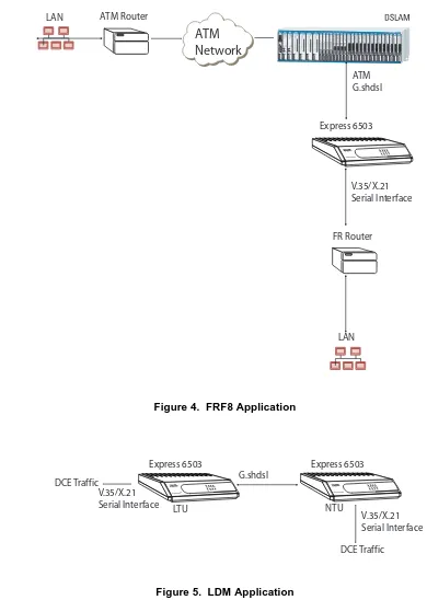
Figure 4. FRF8 Application . . . 8
Figure 5. LDM Application . . . 8
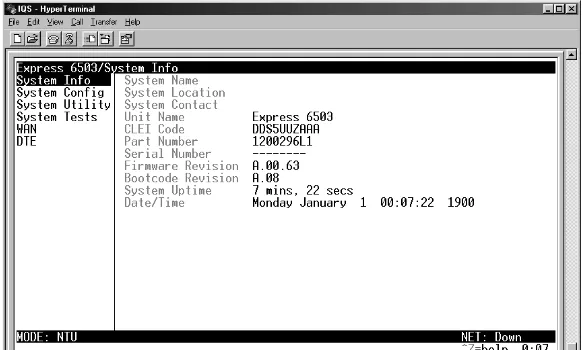
Figure 6. System Information Menu . . . 9
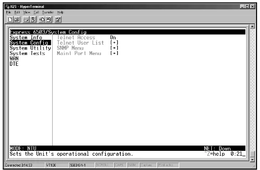
Figure 7. System Configuration Menu . . . 11
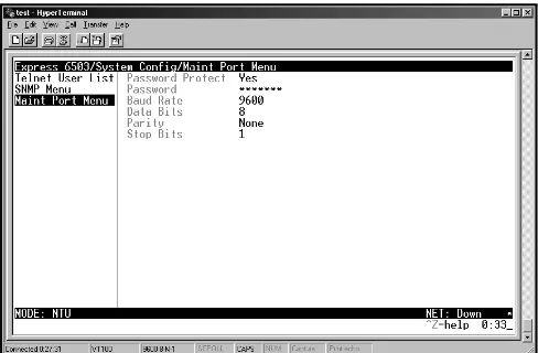
Figure 8. Maintenance Port Menu . . . 13
Figure 9. System Utility Menu . . . 15
Figure 10. System Tests Menu . . . 19
Figure 11. ATM Config Menu . . . 25
Figure 12. ATM Stats Menu . . . 26
Figure 13. Wan Sub Menu . . . 28
Figure 14. SHDSL Config/Stats Menu. . . 29
Figure 15. DTE Select/Config Menu . . . 35
Figure 16. Top-level Terminal Menu Window . . . 36
1.
EXPRESS 6503 OVERVIEW
The Express 6503 is a serial (DCE) to SHDSL data service unit (DSU) designed for small offices and branch offices to provide cost-effective access to high-speed SHDSL services. The Express 6503 preserves the customer's investment in existing business class routers, allowing them to take advantage of New World applications and Packet Telephony. It offers an economical migration path utilizing ATM and Frame Relay over SHDSL without requiring replacement of existing networking equipment.
The Express 6503 provides small offices and branch offices with fast, affordable, and easy-to-use access to the Internet and corporate network. The Express 6503 makes DSL services and applications accessible to the office router or to the desktop. It supports an integrated SHDSL WAN interface and a serial interface to the router and can operate at symmetric speeds of up to 2312 kbps.
On the Express 6503, the terminal menu is the access point to all other operations. Each terminal menu item has several functions and submenus that identify and provide access to specific operations and parameters. These menu selections are described later in this User Interface Guide (pages 18 and following).
Express 6503 Features and Benefits
• SHDSL WAN Support (ITU-T G.991.2) - The Express 6503 supports serial full duplex bidirectional data transport of up to 2312 kbps.
• ITU G.hs (ITU-T G.994.1) Support
• TC PAM Line Encoding - Compliant with the SHDSL standard. • Back-to-back operation for Campus LAN applications.
• Synchronous Serial Interface - The serial interface can support either V.35 or X.21 protocols. • AAL5 ATM Adaptation Layer Type 5 Support.
• FRF.8 Frame Relay to ATM Interworking Support - The Express 6503 supports FRF.8 Frame/ATM service interworking. It maps Frame data-link connection identifiers (DLCIs) to ATM permanent virtual circuits (PVCs); up to four VCs can be configured in the Express 6503.
• FRF.5 Frame Relay to ATM Interworking Support - DLCIs can be assigned automatically or provisioned.
• Management Support - The Express 6503 is managed through a command-line interface accessible locally through the management serial port or remotely through Layer 3 in-band management features. • Safety and Compliance - The Express 6503 is designed for worldwide safety and electromagnetic
certifications (EMC).
Front Panel
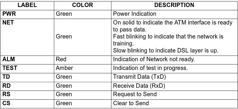
Figure 1 shows the Express 6503 front panel, which contains eight LEDs. Table 1 describes these LEDs.
Figure 1. Express 6503 Front Panel
Table 1. Front Panel LEDs
Rear Panel
The Express 6503 rear panel (Figure 2) contains the following connectors:
LABEL COLOR DESCRIPTION
PWR Green Power Indication
NET
Green
On solid to indicate the ATM interface is ready to pass data.
Fast blinking to indicate that the network is training.
Slow blinking to indicate DSL layer is up.
ALM Red Indication of Network not ready.
TEST Amber Indication of test in progress.
TD Green Transmit Data (TxD)
RD Green Receive Data (RxD)
RS Green Request to Send
CS Green Clear to Send
NETWORK SHDSL interface
X.21 serial interface
V.35 serial interface
CRAFT management/control
90-240/VAC 50/60Hz .1A power input
Express 65034
ALM PWR NET TEST
Figure 2. Rear Panel
Connector Pinouts
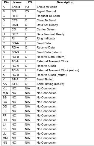
Table 2 below and Table 3 on page 17 give the pinouts for the V.35 and X.21 connectors.
Table 2. X.21 Interface
Pin Name I/O Description
1 Shield I/O Shield for cable
2 TD-A I Transmitted Data
3 RTS-A I Request to Send
4 RD-A O Received Data
5 CD-A O Carrier Detect
6 CLK-A O Signal Timing
7 ETC-A I External Transmit Clock
8 SG I/O Signal Ground
9 TD-B I Transmit Data (return)
10 RTS-B I Request To Send (return)
11 RD-B O Receive Data (return)
12 CD-B O Carrier Detect (return)
13 CLK-B O Signal Timing (return)
14 ETC-B I External Transmit Clock (return)
15 NC N/A No Connection
I= Input, O= Output, N/A= Not Applicable
NETWORK
V.35
CRAFT
Table 3. V.35 Interface
Pin Name I/O Description
A Shield I/O Shield for cable
B SG I/O Signal Ground
C RTS I Request To Send
D CTS O Clear To Send
E DSR O Data Set Ready
F CD O Carrier Detect
H DTR I Data Terminal Ready
J* RI O Ring Indicator
P SD-A I Send Data
R RD-A O Receive Data
S SD-B I Send Data (return)
T RD-B O Receive Data (return)
U TC-A I External Transmit Clock
V RC-A O Receive Clock
W TC-B I External Transmit Clock (return)
X RC-B O Receive Clock (return)
Y ST-A O Send Timing
AA ST-B O Send Timing (return)
K,L NC N/A No Connection
M,N NC N/A No Connection
BB NC N/A No Connection
CC NC N/A No Connection
DD NC N/A No Connection
EE NC N/A No Connection
FF NC N/A No Connection
HH NC N/A No Connection
JJ NC N/A No Connection
KK NC N/A No Connection
LL NC N/A No Connection
MM NC N/A No Connection
NN NC N/A No Connection
*Pin J (ring indicator) is needed for most video conferencing applications.
2.
SPECIFICATIONS
Hardware
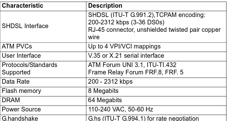
Table 4. Express 6503 Specifications
Table 5. Express 6503 Power and Environmental Specifications and Approvals Characteristic Description
SHDSL Interface
SHDSL (ITU-T G.991.2),TCPAM encoding: 200-2312 kbps (3-36 DS0s)
RJ-45 connector, unshielded twisted pair copper wire
ATM PVCs Up to 4 VPI/VCI mappings
User Interface V.35 or X.21 serial interface
Protocols/Standards Supported
ATM Forum UNI 3.1, ITU-TI.432 Frame Relay Forum FRF.8, FRF. 5
Data Rate 200 - 2312 kbps
Flash memory 8 Megabits
DRAM 64 Megabits
Power Source 110-240 VAC, 50-60 Hz
G.handshake G.hs (ITU-T G.994.1) for rate negotiation
Characteristic Description
AC input voltage 110-240 VAC
AC input current ~.1 Amps
Operating
Temperature Range 32 to 122 deg F (0 to 50 deg C)
Operating humidity Humidity: 5 to 90% noncondensing
Power Requirements 110-240 VAC @ ~.1 Amps
Dimensions (H x W x
D) 1.5 in. x 9.0 in. x 6.25 in.
Weight (average
shipping) 1.5 lbs (0.68 kg)
Regulatory Approvals and Compliance
FCC Part 15, Class B
Standards Compliance
• ATM Forum
• Frame Relay FRF.5 and FRF.8
Management
• Command Line Interface
3.
SHDSL APPLICATIONS
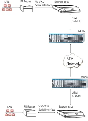
Figure 3 below, Figure 4 on page 20, and Figure 5 on page 20 show some typical applications for the Express 6503. DS3MX POWER STATUS TEST LOCKOUT ON LINE APS TEST/ ENABLE 1181020L1DS3MX POWER STATUS TEST LOCKOUT ON LINE APS TEST/ ENABLE 1181020L1 SCU FSE MODE SELECT ALM HSTACO CR AF T ACO 1181015L1 HTU-C 1181101L1 PWR DSX TXEQRX TXMON RX TST LP1 LP2ALM ACTGRN=NORM YEL=MAN HTU-C 1181101L1 PWR DSX TXEQ RX TXMON RX TST LP1 LP2ALM ACTGRN=NORM YEL=MAN HTU-C1181101L1 PWR DSX TXEQ RX TXMON RX TST LP1 LP2 ALM ACTGRN=NORMYEL=MAN HTU-C1181101L1 PWR DSX TXEQ RX TXMONRX TST LP1 LP2ALM ACTGRN=NORM YEL=MAN HTU-C 1181101L1 PWR DSX TXEQ RX TXMONRX TSTLP1 LP2ALM ACTGRN=NORM YEL=MAN HTU-C1181101L1 PWR DSX TXEQ RX TXMONRX TSTLP1 LP2 ALM ACTGRN=NORM YEL=MAN HTU-C 1181101L1 PWR DSX TXEQRX TXMON RX TST LP1 LP2ALM ACTGRN=NORM YEL=MAN HTU-C 1181101L1 PWR DSX TXEQ RX TXMON RX TST LP1 LP2ALM ACTGRN=NORM YEL=MAN HTU-C1181101L1 PWR DSX TXEQ RX TXMON RX TST LP1 LP2 ALM ACTGRN=NORMYEL=MAN HTU-C1181101L1 PWR DSX TXEQ RX TXMONRX TST LP1 LP2ALM ACTGRN=NORM YEL=MAN HTU-C 1181101L1 PWR DSX TXEQ RX TXMONRX TSTLP1 LP2ALM ACTGRN=NORM YEL=MAN HTU-C1181101L1 PWR DSX TXEQ RX TXMONRX TSTLP1 LP2 ALM ACTGRN=NORM YEL=MAN HTU-C1181101L1 PWR DSX TXEQ RX TXMONRX TSTLP1 LP2 ALM ACT GRN=NORMYEL=MAN HTU-C1181101L1 PWRDSX TXEQRX TXMONRX TSTLP1 LP2 ALM ACT GRN=NORM YEL=MAN HTU-C1181101L1 PWRDSX TXEQRX TXMONRX TST LP1LP2 ALM ACT GRN=NORM YEL=MAN HTU-C1181101L1 PWRDSX TXEQRX TXMON RX TST LP1LP2 ALM ACTGRN=NORMYEL=MAN HTU-C1181101L1 PWRDSX TXEQRX TXMON RX TST LP1LP2 ALM ACTGRN=NORM YEL=MAN HTU-C 1181101L1 PWR DSX TXEQRX TXMON RX TST LP1LP2 ALM ACTGRN=NORM YEL=MAN HTU-C 1181101L1 PWR DSX TXEQRX TXMON RX TST LP1 LP2 ALM ACTGRN=NORMYEL=MAN QFC-C DSX PWR DSXDSX TST ALM ACTA PS
GRN = NORMYEL = MAN
1181300L1 DSX #2 #3#4 #1 QFC-C DSX PWR DSX DSXTST ALM ACTAP S
GRN = NORM
YEL = MAN
1181300L1 DSX#2 #3 #4 #1 QFC-C DSX PWR DSX DSXTST ALM ACTAP S
GRN = NORM
YEL = MAN
1181300L1 DSX#2 #3 #4 #1 QFC-C DSX PWR DSX DSXTST ALM ACTAP S
GRN = NORMYEL = MAN
1181300L1
DSX#2
#3 #4 #1
HD-10 BRI Mux
POWER DSX LBK1 2 34 5 67 8 910 DSL
1181200L1HD-10 BRI Mux
POWER DSX LBK1 2 34 5 67 8 910 DSL 1181200L1 HD-10 BRI Mux
POWER DSX LBK 12 3 45 6 78 9 10 DSL 1181200L1 HD-10 BRI Mux
POWER DSX LBK 12 3 45 6 78 9 10DSL 1181200L1 T1-OR PWR DSX LBKLP ALM TXR X 6V + – AP S TX MON ACT
GRN = NORM YEL = MAN
RX 1181310L1T1-OR PWR DSX LBKLP ALM T X R X 6V + – AP S TXMON ACT
GRN = NORM YEL = MAN
RX 1181310L1T1-OR PWR DSX LBKLP ALM T X R X 6V + – AP S TX MON ACT
GRN = NORMYEL = MAN
RX 1181310L1 T1-OR PWRDSX LBKLP ALM T X R X 6V + – A PS TX MON ACT
GRN = NORM YEL = MAN
RX 1181310L1 HTU-C 1181101L1 PWR DSX TXEQRX TXMON RX TST LP1LP2 ALM ACTGRN=NORMYEL=MAN
Express 65034
ALM PWR NETTEST
RS TDRDCS
ATM
Network
FR Router LAN V.35/X.21 Serial Interface Express 6503 ATM G.shdsl DS3MX POWER STATUS TEST LOCKOUT ON LINE APS TEST/ ENABLE 1181020L1DS3MX POWER STATUS TEST LOCKOUT ON LINE APS TEST/ ENABLE 1181020L1 SCU FSE MODE SELECT ALM HSTACO CR AF T ACO 1181015L1 HTU-C1181101L1 PWR DSX TXEQ RX TXMON RX TST LP1 LP2 ALM ACTGRN=NORMYEL=MAN HTU-C1181101L1 PWR DSX TXEQ RX TXMONRX TST LP1 LP2ALM ACTGRN=NORMYEL=MAN HTU-C1181101L1 PWR DSX TXEQ RX TXMONRX TSTLP1 LP2ALM ACTGRN=NORM YEL=MAN HTU-C1181101L1 PWR DSX TXEQ RX TXMONRX TSTLP1 LP2 ALM ACTGRN=NORM YEL=MAN HTU-C1181101L1 PWR DSX TXEQ RX TXMONRX TSTLP1 LP2 ALM ACT GRN=NORMYEL=MAN HTU-C1181101L1 PWRDSX TXEQRX TXMONRX TSTLP1 LP2 ALM ACT GRN=NORM YEL=MAN HTU-C1181101L1 PWR DSX TXEQ RX TXMON RX TST LP1 LP2 ALM ACTGRN=NORMYEL=MAN HTU-C1181101L1 PWR DSX TXEQ RX TXMONRX TST LP1 LP2ALM ACTGRN=NORMYEL=MAN HTU-C1181101L1 PWR DSX TXEQ RX TXMONRX TSTLP1 LP2ALM ACTGRN=NORM YEL=MAN HTU-C1181101L1 PWR DSX TXEQ RX TXMONRX TSTLP1 LP2 ALM ACTGRN=NORM YEL=MAN HTU-C1181101L1 PWR DSX TXEQ RX TXMONRX TSTLP1 LP2 ALM ACT GRN=NORMYEL=MAN HTU-C1181101L1 PWRDSX TXEQRX TXMONRX TSTLP1 LP2 ALM ACT GRN=NORM YEL=MAN HTU-C 1181101L1 PWRDSX TXEQRX TXMONRX TST LP1LP2 ALM ACT GRN=NORM YEL=MAN HTU-C1181101L1 PWRDSX TXEQRX TXMON RX TST LP1LP2 ALM ACTGRN=NORMYEL=MAN HTU-C1181101L1 PWRDSX TXEQRX TXMON RX TST LP1LP2 ALM ACTGRN=NORM YEL=MAN HTU-C 1181101L1 PWRDSX TXEQRX TXMON RX TST LP1LP2 ALM ACTGRN=NORM YEL=MAN HTU-C 1181101L1 PWR DSX TXEQRX TXMON RX TST LP1LP2 ALM ACTGRN=NORM YEL=MAN HTU-C 1181101L1 PWR DSX TXEQ RX TXMON RX TST LP1 LP2ALM ACTGRN=NORMYEL=MAN HTU-C1181101L1 PWR DSX TXEQ RX TXMON RX TST LP1 LP2ALM ACTGRN=NORM YEL=MAN QFC-C DSX PWR DSX DSXTST ALM ACTAP SGRN = NORM
YEL = MAN
1181300L1 DSX#2 #3 #4 #1 QFC-C DSX PWR DSX DSXTST ALM ACTAP S
GRN = NORM YEL = MAN
1181300L1 DSX#2 #3 #4 #1 QFC-C DSX PWR DSX DSXTST ALM ACTAP S
GRN = NORMYEL = MAN
1181300L1 DSX #2#3 #4 #1 QFC-C DSX PWR DSX DSXTST ALM ACTAP S
GRN = NORM YEL = MAN
1181300L1
DSX #2#3
#4 #1
HD-10 BRI Mux
POWER DSX LBK1 2 34 5 67 8 910 DSL 1181200L1 HD-10 BRI Mux
POWER DSX LBK 12 3 45 6 78 9 10DSL 1181200L1 HD-10 BRI Mux
POWER DSX LBK 12 3 45 6 78 9 10DSL
1181200L1HD-10 BRI Mux
POWER DSXLBK 1 23 4 56 7 89 10 DSL 1181200L1 T1-OR PWR DSX LBKLP ALM T X R X 6V + – AP S TXMON ACT
GRN = NORMYEL = MAN
RX 1181310L1T1-OR PWR DSX LBKLP ALM T X R X 6V + – A PS TX MON ACT
GRN = NORM YEL = MAN
RX 1181310L1 T1-OR PWRDSX LBK LPALM T X R X 6V + – A PS TX MON ACT
GRN = NORM YEL = MAN
RX 1181310L1 T1-OR PWRDSX LBK LPALM T X R X 6V + – A PS TX MON ACT
GRN = NORMYEL = MAN
Figure 4. FRF8 Application
Figure 5. LDM Application DS3MX POWER STATUS TEST LOCKOUT ON LINE APS TEST/ ENABLE 1181020L1DS3MX POWER STATUS TEST LOCKOUT ON LINE APS TEST/ ENABLE 1181020L1 SCU FSE MODE SELECT ALM HSTACO CR AF T ACO
1181015L1 HTU-C1181101L1
PWRDSX TXEQRX TXMON RX TST LP1LP2 ALM ACTGRN=NORM YEL=MAN HTU-C 1181101L1 PWR DSX TXEQRX TXMON RX TST LP1LP2 ALM ACTGRN=NORMYEL=MAN HTU-C 1181101L1 PWR DSX TXEQRX TXMON RX TST LP1 LP2ALM ACTGRN=NORM YEL=MAN HTU-C 1181101L1 PWR DSX TXEQ RX TXMON RX TST LP1 LP2ALM ACTGRN=NORM YEL=MAN HTU-C1181101L1 PWR DSX TXEQ RX TXMON RX TST LP1 LP2 ALM ACTGRN=NORMYEL=MAN HTU-C1181101L1 PWR DSX TXEQ RX TXMONRX TSTLP1 LP2ALM ACTGRN=NORMYEL=MAN HTU-C1181101L1 PWRDSX TXEQRX TXMON RX TST LP1LP2 ALM ACTGRN=NORM YEL=MAN HTU-C 1181101L1 PWR DSX TXEQRX TXMON RX TST LP1LP2 ALM ACTGRN=NORMYEL=MAN HTU-C 1181101L1 PWR DSX TXEQRX TXMON RX TST LP1 LP2ALM ACTGRN=NORM YEL=MAN HTU-C 1181101L1 PWR DSX TXEQ RX TXMON RX TST LP1 LP2ALM ACTGRN=NORM YEL=MAN HTU-C1181101L1 PWR DSX TXEQ RX TXMON RX TST LP1 LP2 ALM ACTGRN=NORMYEL=MAN HTU-C1181101L1 PWR DSX TXEQ RX TXMONRX TSTLP1 LP2ALM ACTGRN=NORMYEL=MAN HTU-C1181101L1 PWR DSX TXEQ RX TXMONRX TSTLP1 LP2 ALM ACTGRN=NORM YEL=MAN HTU-C1181101L1 PWR DSX TXEQ RX TXMONRX TSTLP1 LP2 ALM ACT GRN=NORM YEL=MAN HTU-C1181101L1 PWR DSX TXEQ RX TXMONRX TSTLP1 LP2 ALM ACT GRN=NORMYEL=MAN HTU-C1181101L1 PWRDSX TXEQRX TXMONRX TSTLP1 LP2 ALM ACT GRN=NORM YEL=MAN HTU-C 1181101L1 PWRDSX TXEQRX TXMONRX TST LP1LP2 ALM ACTGRN=NORM YEL=MAN HTU-C1181101L1 PWRDSX TXEQRX TXMON RX TST LP1LP2 ALM ACTGRN=NORMYEL=MAN HTU-C1181101L1 PWRDSX TXEQRX TXMON RX TST LP1LP2 ALM ACTGRN=NORM YEL=MAN QFC-C DSX PWR DSXDSX TST ALM ACTA PS
GRN = NORM
YEL = MAN
1181300L1 DSX #2 #3#4 #1 QFC-C DSX PWR DSXDSX TST ALM ACTA PS
GRN = NORMYEL = MAN
1181300L1 DSX #2 #3#4 #1 QFC-C DSX PWR DSXDSX TST ALM ACTAP S
GRN = NORM
YEL = MAN
1181300L1 DSX#2 #3 #4 #1 QFC-C DSX PWR DSX DSXTST ALM ACTAP S
GRN = NORM
YEL = MAN
1181300L1
DSX#2
#3 #4 #1
HD-10 BRI Mux
POWER DSXLBK 1 23 4 5 67 8 910 DSL
1181200L1HD-10 BRI Mux
POWER DSX LBK1 2 34 5 67 8 910 DSL
1181200L1HD-10 BRI Mux
POWER DSX LBK1 2 34 5 67 8 9 10DSL 1181200L1 HD-10 BRI Mux
POWER DSX LBK 12 3 45 6 78 9 10DSL 1181200L1 T1-OR PWR DSXLBK LP ALM TXRX 6V+ – AP S TX MON ACT
GRN = NORMYEL = MAN
RX 1181310L1T1-OR PWR DSXLBK LP ALM TXRX 6V+ – AP S TX MON ACT
GRN = NORM YEL = MAN
RX 1181310L1T1-OR PWR DSX LBKLP ALM T X R X 6V + – AP S TXMON ACT
GRN = NORM YEL = MAN
RX 1181310L1T1-OR PWR DSX LBKLP ALM T X R X 6V + – AP S TX MON ACT
GRN = NORMYEL = MAN
RX 1181310L1HTU-C1181101L1
PWRDSX TXEQRX TXMON RX TST LP1LP2 ALM ACTGRN=NORM YEL=MAN
ATM
Network
ATM Router LANExpress 65034
ALM PWR NETTEST
RS TDRDCS Express 6503 ATM G.shdsl V.35/X.21 Serial Interface FR Router LAN
Express 65034
ALM PWR NETTEST
RS TDRDCS Express 6503
DCE Traffic G.shdsl
LTU
Express 65034
ALM PWR NETTEST
4.
CONFIGURING THE EXPRESS 6503
System Info
The SYSTEM INFO menu provides basic information about the unit and contains data fields for editing
information. Figure 6 displays the items available when you select this menu item.
Figure 6. System Information Menu
>System Name
Provides a user-configurable text string for the name of the Express 6503. This name can help you distinguish between different installations. You can enter up to 31 alpha-numeric characters in this field, including spaces and special characters (such as an underbar). This name will appear on the top line of all screens.
>System Location
Provides a user-configurable text string for the location of the Express 6503. This field is to help you keep track of the actual physical location of the unit. You can enter up to 31 alphanumeric characters in this field, including spaces and special characters (such as an underbar).
>System Contact
Provides a user-configurable text string for a contact name. You can use this field to enter the name, phone number, or email address of a person responsible for the Express 6503. You can enter up to 31
alpha-numeric characters in this field, including spaces and special characters (such as an underbar).
> Part Number
ADTRAN part number for the Express 6503.
>Serial Number
Serial number of the Express 6503.
>Firmware Revision
Displays the current firmware revision level of the Express 6503.
>Bootcode Revision
Displays the bootcode revision.
>System Uptime
Displays the length of time since the Express 6503 reboot.
>Date/Time
Displays the current date and time, including seconds. This field can be edited. Enter the time in 24-hour format (such as 23:00:00 for 11:00 pm). Enter the date in mm-dd-yyyy format (for example, 10-30-2001).
System Config
Set up the Express 6503 operational configuration from the SYSTEM CONFIG menu. Figure 7 shows the items included in this menu.
Figure 7. System Configuration Menu
>Telnet Access
This parameter determines whether the unit allows telnet access over the SHDSL link. The choices are ON
and OFF. The factory default setting is ON.
>Telnet User List
The telnet user list defines the users which are allowed telnet access and the rules governing that access. Name
Up to four users can be configured for access to the Express 6503. Each user can be assigned a security level and time out. The name is a text string of the user name for this session. You can enter up to 15 characters in this field. The factory default is no entry in the NAME field.
Authen Method
The user can be authenticated by selecting:
The factory default is PASSWORD. Password
When the authenticating method is password, this text string is used for the password. You can Password The Password field is used to authenticate the user.
Level
This is the security level granted to the user. The table below gives a brief description of each level. The factory default is 0.
>SNMP Menu
The Express 6503 is an SNMP agent. It can respond to Gets and Sets, and can generate traps. This menu sets up the access, communities, and traps.
Access
This parameter determines whether the unit allows SNMP management. When set toOFF,
SNMP access is denied. When set to ON, the Express 6503 will respond to SNMP managers
based on the configuration. The factory default is ON.
Communities
This list is used to set up to eight SNMP community names that the Express 6503 will allow. Factory default sets the community "public" with "Get" privileges only.
Name
This is a text string for the community name. You can enter up to 31 characters in this field. The factory default setting is no entry in this field.
Privilege
The access for this manager can be assigned three levels. The factory default is NONE.
Manager IP
This is the IP address of SNMP manager. If set to 0.0.0.0, any SNMP manager can access the Express 6503 for this community. The factory default is 0.0.0.0.
Select level... If you want the user to....
5 Have read-only permission for all menu items - minimum rights
4 Have read permission for all menu items and permission to use test commands
3 Have access to all commands except passwords, flash download,
authentication methods, interface configurations, and telnet security levels.
2 Have access to all commands except passwords, flash download,
authentication methods, and telnet security levels.
1 Have access to all commands except passwords and telnet security levels.
0 Have permission to edit every menu item, including creating and editing
passwords -- maximum rights
None No access is allowed for this community or manager.
Get Manager can only read items.
Traps
This list defines the manager IP and the manager name. Manager Name
The Express 6503 can generate SNMP traps. This list allows up to four managers to be listed to receive traps.
MANAGER NAME is the text string describing the name of the entry. It is intended for easy
reference and has no bearing on the SNMP trap function. You can enter up to 31 characters in this field. The factory default is no entry in the manager name field.
Manager IP
This is the IP address of the manager that is to receive the traps. The factory default is 0.0.0.0.
>Maint Port Menu
The Express 6503 VT 100 CRAFT port is located on the rear panel. The setup for this port is under this menu (Figure 8).
Figure 8. Maintenance Port Menu
Password Protect
When set to NO, the maintenance port is not password protected. When YES (def), the Express
6503 will prompt for a password upon startup. Password
Baud Rate
This is the asynchronous rate that the maintenance port will run. The possible values are 300, 1200, 2400, 4800, 9600 (def), 19200, 38400, 57600, and 115200.
Data Bits
This is the asynchronous bit rate that the maintenance port will run. The possible values are 7
or 8 (def) bits. Parity
This is the asynchronous parity that the maintenance port will run. The possible values are
NONE(def), ODD, or EVEN.
Stop Bits
This is the stop bit used for the maintenance port. The possible values are 1 (def), 1.5 or 2. Instructions for Changing Passwords
Step Action
1 Select the PASSWORD field—a new PASSWORD field displays.
2 Type the new password in the ENTER field.
3 Type the new password again in the CONFIRM field.
The password can contain up to 15 alphanumeric characters. You can also use spaces and special characters in the
System Utility
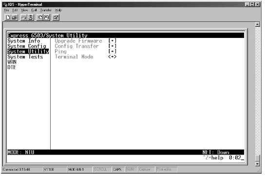
Use the SYSTEM UTILITY menu (Figure 9) to upgrade firmware.
Figure 9. System Utility Menu
>Upgrade Firmware
Updates firmware when Express 6503 enhancements are released. Transfer Method
Two transfer methods are available for use in updating the Express 6503.
The two methods for upgrading are XMODEM and TFTP.TFTP requires a TFTP server running on the network. The Express 6503 starts a TFTP client function which gets the upgrade code from the TFTP server. Selecting XMODEM will load the upgrade code through the CRAFT port using any PC terminal emulator with xmodem capability. The factory default is TFTP. (See Appendix B. Updating Express 6503 Firmware using XMODEM on page 52 for more information.)
TFTP Server Address
This is required when the transfer method is TFTP. It is the IP address or domain name (if DNS is configured) of the TFTP server. The factory default is no entry in the TFTP server address field.
TFTP Server Filename
Start Transfer
This activator is used when the configurable items in this menu are complete.
Abort Transfer
Use this activator to cancel a TFTP transfer in progress.
>Config Transfer
Sends a file containing the Express 6503 configuration to a PC connected to the CRAFT port using XMODEM protocol or to a file on a TFTP server using the TFTP protocol.
CONFIG TRANSFER also lets you save the Express 6503 configuration as a backup file, so you can use the
same configuration with multiple Express 6503 units. In addition, CONFIG TRANSFER can retrieve a configuration file from a TFTP server.
To support these transfers, ADTRAN delivers a TFTP program with the Express 6503 called TFTP Server. You can configure any PC running Microsoft Windows with this software, and store a configuration file.
Transfer Method
Displays the method used to transfer the configuration file to or from a server. XMODEM and TFTP are supported. The factory default setting is TFTP.
Transfer Type
Only Binary transfers are currently supported. TFTP Server IP Address
Specifies the IP address of the TFTP server. Get this number from your system administrator. If using the ADTRAN Utilities TFTP server, this number appears in the TFTP server status window. The factory default value is 0.0.0.0.
TFTP Server Filename
Defines the name of the configuration file that you transfer to or retrieve from the TFTP server. The default name is 6503.cfg, but you can edit this name.
Current Transfer Status
Indicates the current status of the update.
Before using START TRANSFER, the Express 6503 should have a valid IP address, subnet mask, and default gateway (if required).
Previous Transfer Status
Indicates the status of the previous update. Load and Use Config
Retrieves the configuration file specified in the TFTP SERVER FILENAME field from the server. To start this command, enter Y to begin or enter N to cancel.
Save Config Remotely
Saves the configuration file specified in TFTP SERVER FILENAME to the server identified in
TFTP SERVER IP ADDRESS. To start this command, enter Y to begin or enter N to cancel.
>Ping
This menu includes the various ping test parameters such as the activator to control the test, host address, packet size, and number of packets.
Start/Stop
Activator to start and cancel a ping test.
Host Address
IP address or domain name (if DNS is configured) of device to receive the ping. The factory default is no entry in the host address field.
Size (40-1500)
Total size of the ping to send. Range is 40 to 1500 bytes. The default is 64.
# of Packets
Total packets to send every 2 seconds. Setting this to 0 allows the client to ping continuously. The default is 1.
If you execute this command, the Express 6503 retrieves the configuration file, reboots, then restarts using the new configuration.
Before using this command, you must have identified a valid TFTP server in TFTP SERVER
IP ADDRESS.
# Transmits
Total packets sent (read only). # Receives
Total packets received (read only). % Loss
Percentage loss based on ping returned from host (read only).
>Terminal Mode
The terminal mode gives the user a command-line prompt. From this prompt, you can: • Perform a reset with the command "reset."
• Perform a factory restore with the command "fact restore."
• Configure the unit. The Express 6503 has the ability to download a text file which contains the configuration of the entire unit. This configuration may then be altered in a text editor, and then uploaded to that same or any other Express 6503.
System Test
Use the SYSTEM TESTmenu (Figure 10) to test and debug typical applications.
Figure 10. System Tests Menu
>DTE Loopback
All data is looped back to the serial interface. The choices are DTE LPBKON and DTE LPBKOFF. The factory default setting is DTE LPBKOFF.
>Network Loopback
All data is looped back to the network interface. The choices are DISABLED and ENABLED. The factory default setting is DISABLED.
WAN
This menu defines and displays the ATM/Frame, SHDSL, and IP configuration parameters and statistics.
>ATM/Frame Config/Stats
This menu defines and displays the ATM and frame relay configuration parameters and statistics. ATM/FR IWF
This menu contains the setup and status for the ATM/Frame Relay interworking functions. Mode
FRF8
This is also known as Service Interworking. In this mode, the Express 6503 performs a translation between Frame Relay and ATM protocols.
Configuration
The CONFIGURATION menu is used to support the configuration of Frame-to-ATM
interworking, signaling formats, timeout values, and PVC settings.
The following settings are used for FRF5. DTE FR MAINT
PROTOCOL
Frame Relay maintenance or signaling protocol between local V.35 port and the attached DTE port. This unit supports ANSI Annex A, CCITT Q933 Annex D, CISCO LMI or Static (no signaling). The factory
default setting is LMI.
DTE FR POLL TIMEOUT T392 (5-30)
T392 for signaling protocol. The factory default setting is 15. This parameter has no meaning if the Maint Protocol is set to
STATIC (no signaling).
NTWK FRM PORT CONFIGURE
Logical Frame Relay ports over ATM. Up to 4 ports are supported with each port supporting up to 4 DLCI mappings (max of
4 DLCIs per PVC). Go to NUM field. Typing
"i" or "I" will insert another entry, and typing "d" or "D" will delete one entry.
NAME To identify your port. You can enter up to 31
characters in this field. The factory default setting is no entry in this field.
ATM VPI Specifies the virtual path over which this logical port is running. The range is 0-255. The factory default setting is 0.
ATM VCI Specifies the virtual circuit over which this logical port is running. The range is
0-65535. The factory default setting is 38.
PCR Peak Cell Rate for ATM. The range is
0-5434. The factory default setting is 5434.
SCR Sustained Cell Rate for Variable Bit Rate
(VBR) connections. SCR is used to ensure critical service base on an average rate below PCR. The factory default setting is 0.
MBS Maximum Burst Size is the number of cells
that can be sent over PCR connections.
QOS Quality of Service. The choices are ATM
DE MAP Maps Frame Relay Discard Eligible (DE) bit to the ATM Cell Loss Priority (CLP) bit. The
choices are CLP ALWAYS 0, CLP ALWAYS
1, and MAP DE TO CLP. The factory
default setting is CLP ALWAYS 0.
CLPI MAP Maps ATM Cell Loss Priority (CLP) bit to the Frame Relay (DE) bit. The choices are
NO MAP CLP and MAP CLP TO DE. The
factory default setting is NO MAP CLP.
D/C Sets the Data/Control (DC) bit in the header
to either 0 or 1. The factory default setting is set 0 (1 is not commonly used).
HEADER This field specifies the header length format. The support of a 2 byte header is mandatory in the Networking
Internetworking (FRF5) specifications. The 3 byte header is for experimentation and the 4 byte header support is optional in FRF5 specifications. The choices are 2
BYTES, 3 BYTES, or 4 BYTES. The factory
default setting is 2 BYTES.
MAINT PROTOCOL Specifies the maintenance protocol. The
choices are ANNEX D, ANNEX A, LMI, and
STATIC. The factory default setting is
ANNEX D.
MUX MODE Many DLCIs or one DLCI mapping over this port. There is a one to one ratio for logical Frame Relay Connections to ATM Virtual Channel Connection (VCC) and this is the
ONE TO ONE option. The DLCI range is 16-991 and the DLCI is agreed upon by the ATM end users’ systems; if not, the ATM end system must use the default value of 1022. The other method of multiplexing is
MANY TO ONE where several logical Frame Relay connections are multiplexed into one
ATM VCC. The MANY TO ONE method is only
used for Frame Relay PVCs that terminate on the same local ATM system. The
choices are ONE TO ONE or MANY TO ONE.
The factory default setting is ONE TO ONE.
The following settings are used for FRF8.
OAM CC OAM CC cells are continuity check cells used to verify the integrity of an ATM PVC. OAM CC responds to continuity check cells when enabled. This option is used
particularly for compatibility with the Newbridge ATM switch. The choices are
ENABLE and DISABLE. The factory default
setting is DISABLE.
DTE FR Maint Protocol Frame Relay maintenance or signaling
protocol between local V.35 port and the attached DTE port. This unit supports ANSI Annex A, CCITT Q933 Annex D, CISCO LMI or Static (no signaling). The factory
default setting is LMI.
DTE FR Poll Timeout T392 (5-30)
T392 for signaling protocol. The factory default setting is 15. This parameter has no meaning if the Maint Protocol is set to
STATIC (no signaling).
Fr/ATM PVC Mapping Up to 4 mappings are supported.
FrDLCI Frame Relay DLCI on V.35 port. The range is 16-1007. The factory default setting is 0.
ATM VPI Specifies the virtual path to which DLCI is mapped. The range is 0-255. The factory default setting is 0.
ATM VCI Specifies the virtual circuit to which DLCI is mapped. The range is 0-65535. The factory default setting is 38.
PCR Peak Cell Rate for ATM. The range is
0-5434. The factory default setting is 5434.
QOS Quality of Service. The choices are ATM
UBR and VBR NON-REAL TIME. The factory default setting is UBR.
Translate Network providers have the ability to provision each PVC pair with an encapsulation mode to ensure interoperability between terminal
equipment. The two modes are transparent
and translation. Translation (TRANSLATE)
mode is most common and carries multiple upper layer protocols over Frame Relay
and ATM PVCs. The choices are NO and
YES. The factory default setting is YES.
De Map Map Frame Relay DE bit to ATM CLPI bit.
The choices are ALWAYS 0, ALWAYS 1, and
Status
Frame Relay
(These stats are available when the mode is set to FRF 5 or FRF8).
FECN Allows mapping of Frame Relay FECN
(Forward Explicit Congestion Notification) bit to ATM EFCI (Explicit Forward
Congestion Indicator) bit. The choices are
NO MAP FECN and MAP FECN. The
factory default setting is NO MAP FECN.
OAM CC OAM CC cells are continuity check cells used to verify the integrity of an ATM PVC. OAM CC responds to continuity check cells when enabled. This option is used for
compatibility with the Newbridge ATM
switch. The choices are ENABLE and
DISABLE. The factory default setting is
DISABLE.
Ports
Port Index Port number.
Signal State Frame relay state.
Tx Frames Number of frames transmitted.
Rx Frames Number of frames received.
Tx Bytes Number of bytes transmitted.
Rx Bytes Number of bytes received.
Signal TX Frames Number of Frame Relay signaling packets
transmitted out the port.
Signal RX Frames Number of Frame Relay signaling packets
received by the port.
Drop Unknown DLCI Number of frames received that were not
associated with any known PVC.
Drop Invalid DLCI Number of frames received that had illegal
DLCIs.
Clear Stats When activated, this field will clear all frame
relay port stats.
PVCs
Port Port number.
DLCI DLCI number.
IWF Status
(These stats are only available when the mode is set to FRF8). DE Count Number of packets received on an
individual DLCI with the DE bit set.
CR Count Number of packets received on an
individual DLCI with the CR bit set.
BECN Count Number of packets received on an
individual DLCI with the BECN bit set.
FECN Count Number of packets received on an
individual DLCI with the FECN bit set.
Unknown Frame RX Frames received that were not associated
with any PVC entries.
DLCI Displays the DLCI number.
DLCI State Displays the DLCI state. If the DLCI is operational, this field will display active. If the DLCI is not operational, this field will display inactive.
ATM VPI Displays the ATM VPI number.
ATM VCI Displays the ATM VCI number.
ATM State Possibilities: ACTIVE, CONFIRM, CREATED, CONGESTION
DE Displays how the DE map is configured.
Choices are ALWAYS 0, ALWAYS 1, and
CONVERT.
FECN Displays how the FECN map is configured.
Choices are NO MAP FECN and MAP FECN.
AAL Status Shows status of AAL frames.
Max PDU Size Maximum Protocol Data Unit size for the
ATM AAL5 frame.
TX Data Bytes Number of AAL5 data bytes transmitted.
TX Frames Number of AAL5 frames transmitted.
TX Cells (All Types) Total number of AAL5 cells transmitted
(all types).
TX OAM Cells Number of AAL5 OAM cells transmitted.
TX RM Cells Number of AAL5 RM cells transmitted.
TX ERCI=1 Cells Number of AAL5 ERCI=1 cells
transmitted.
TX CLPI=1 Cells Number of AAL5 CLPI=1 transmitted.
RX Data Bytes Number of AAL5 data bytes received.
RX Frames Number of AAL5 frames received
ATM Config
Use the ATM CONFIG menu (Figure 11) to set the parameters listed below. RX Bad OAM Cells Number of AAL5 Bad OAM cells
received
RX RM Cells Number of AAL5 RM cells received
RX Bad RM Cells Number of AAL5 Bad RM cells received
RX EFCI=1 Cells Number of AAL5 ERCI=1 cells received.
RX CLPI=1 Cells Number of AAL5 CLPI=1 cells received.
Discard RX Cells Number of AAL5 RX cells which were
discarded.
Discard RX Frames Number of AAL5 RX frames which were
discarded.
Discard TX Frames Number of AAL5 TX frames which were
discarded.
TX Queue Overflow Number of cells discarded due to queue
overflow.
TX Out of Cells Number of AAL5 TX Out of Cells.
TX Inactive Number of TX frames discarded while
PVC is inactive.
RX Inactive Number of RX frames discarded while
PVC is inactive.
CRC Errors Number of AAL5 CRC Errors.
Reassembly
Idle Cells
The IDLE CELLS format must be configured for either ATM FORUM (UNASSIGNED) or ITU (IDLE). Configuring this setting incorrectly for a particular circuit will cause poor performance at the ATM layer. The factory default setting is ATM FORUM (UNASSIGNED).
Data Scrambling
DATA SCRAMBLING can be ENABLED or DISABLED for cell traffic. Configuring this setting
incorrectly for a particular circuit will cause poor performance at the ATM layer. The factory default setting is DISABLED.
ATM Stats
Use the ATM STATS menu (Figure 12) to set the parameters listed below.
Figure 12. ATM Stats Menu
AP: TxCells
This is the number of cells transmitted.
This setting must match the configuration setting of the ATM switch or DSLAM at the other end of the circuit.
AP: RxCells
This is the number of cells received. AP: RxOAMCells
This is the number of OAM cells received AP: ReceiveCellsDiscarded
This is the number of cells received and discarded for an unconfigured PVC. AP: ReceiveCellErrors
This is the number of cells received with an HEC error. AP: Sync
This indicates cell delineation at the ATM layer. AP: OutOfCellDelineation
This indicates loss of cell delineation at the ATM layer. AAL5: TransmitFrames
This is the number of AAL5 frames transmitted. AAL5: ReceiveFrames
This is the number of AAL5 frames received. AAL5: TransmitDiscardedFrames
This is the number of AAL5 frames discarded. AAL5: ReceiveErrors
This is the number of AAL5 errors received. AAL5: ReceiveDiscardedFrames
This is the number of AAL5 frames discarded. Clear Stats
Clear Channel
Clear channel is a protocol used to transmit data between end users. The default is disabled. This option is found under the Wan Sub Menu.
>SHDSL Config/Stats
Figure 14 below shows this menu.
Figure 14. SHDSL Config/Stats Menu
SHDSL Config
NTU/LTU Mode
NTU
Network termination unit or remote device. Set the mode to NTU for network connections. The factory default setting is NTU.
LTU
Line termination unit or host device. Set the mode to LTU for CPE connections. Data Rate
Select the data rate of the SHDSL network connection. The choices are 3-36 DS0s with 64K per DS0. The factory default is 2312 KBPS (36 DS0S).
Frame Mode
Type of framing required. SHDSL Framed
RADSL (Auto/Fixed)
Select AUTO or FIXED. The factory default setting is fixed. SHDSL Stats
Training State
This field is for internal ADTRAN use only. NTU/LTU Mode
Displays the mode the unit is set for (NTU or LTU). Data Rate
Displays the data rate of the SHDSL network connection. Frame Mode
Displays the type of framing (either SHDSL Framed or SHDSL Framed Plesio w/bit stuffing). G.hs Event
This field is for internal ADTRAN use only. G.hs State
This field is for internal ADTRAN use only. Annex
Displays the Annex type set in the SHDSL config. SHDSL Eoc Stats
SHDSL Version
ITU-T G.991.2 version supported by remote unit. Vendor List Number
List number of remote unit. Vendor Issue Number Issue number of remote unit. CLEI Code
CLEI code of remote unit. Vendor ID
Vendor ID of remote unit. Manufacture Date
Manufacture date of remote unit. PROM Checksum
Vendor Model Number Model number of remote unit. Vendor Serial Number Serial number of remote unit. Vendor Software Version Software revision of remote unit. Performance Monitoring
SNR Margin (dB)
Signal-to-noise ratio margin on SHDSL line. Loop Attenuation
Loop attenuation on SHDSL line. Errored Seconds
Number of errored seconds on SHDSL line. Severely Errored Seconds
Number of severely errored seconds on SHDSL line. Unavailable Seconds
Number of unavailable seconds on SHDSL line. Code Violations Count
Number of code violations on SHDSL line. Loss of Sync Word Seconds
Number of seconds of sync loss on SHDSL line.
>IP Config/Stats
IP Config
This menu includes the various IP configuration parameters associated with the management PVC. It includes a description field, VPI, VCI, PCR, QOS, Protocol, RFC1483 IP, and OAM CC.
Description
This field provides a user-configurable text string for describing the management PVC. You can enter up to 31 alpha-numeric characters in this field, including spaces and special
VCI
Specifies the virtual circuit to which the management DLCI is mapped. The range is 0-65535. The factory default setting is 38.
PCR
Peak Cell Rate for ATM for the management DLCI. PCR is normally used for UBR connections and can be calculated using the equations below.
Peak Cell Rate = Bit Rate/424 (The total of all PCRs must not exceed the line rate). The range is 0-5434. The factory default setting is 5434.
SCR
Sustained Cell Rate for Variable Bit Rate (VBR) connections. SCR is used to ensure some level of service based on an average rate below PCR. The factory default setting is 0. QOS
Quality of Service for ATM UBR and VBR non-real time for the management DLCI. The factory default setting is UBR.
Protocol
The factory default setting is RFC1483. RFC1483 IP
This menu configures the various RFC1483 IP parameters associated with the management DLCI. This includes the active parameter, far-end and local IP addresses, netmask and various RIP parameters.
Active
Adds this static route entry to the IP routing table when set to YES(default) and removes it (if it was previously added) if set to NO.
Far-End IP Address
The IP address of the host or network address of the device being routed to. Default is 0.0.0.0. IP Netmask
Determines the bits in the previous IP address that are used. If this is to be a host route, it must be set to all ones (255.255.255.255). Default is 0.0.0.0.
Local IP Address
The IP Address of the 6503. Default is 0.0.0.0. OAM CC
OAM CC cells are continuity check cells used to verify the integrity of an ATM PVC. The factory default is disable.
IP Stats
IP Routes
This lists the contents of the Express 6503's IP router table. IP Address
Network or host destination address. Netmask
Network mask applied to the destination address. Gateway
Host or router to receive this packet. Port
Port gateway is located on:
local sent directly to the Express 6503 router wan0Express 6503's first PPP bundle
fr 0...fr 9Express 6503 is connected up to 10 DLCIs Use
Number of times the Express 6503 has referenced the route. MBS
Maximum Burst Size is the total number of cells that can be sent over PCR connections. Flags
Important tags associated with this route entry
Hops
Number of routers that must go through to get to destination. Ranges from 0-15 or 16 for infinite (can’t get there from here).
TTL
Seconds until address is removed from table or “zombied.” Value of 999 means route is static.
H route is a host route
G route is a gateway route
D route learned dynamically from RIP
I route learned from an ICMP redirect
P route is private and is not advertised with RIP
T route is to a triggered port (updates only when table
VCI
Displays the ATM VCI number. TxFrames
Displays the number of frames transmitted. RxFrames
Displays the number of frames received. TxCells
Displays the number of cells transmitted. RxCells
Displays the number of cells received. TxOverflow
Displays the number of cells discarded due to queue overflow TxInactive
Displays the number of Tx frames discarded while PVC is inactive. RxDiscard
Displays the number of cells received and discarded for an unconfigured PVC. RxInactive
Displays the number of Rx frames discarded while PVC is inactive. Rx CRC32 Errors
Displays the number of errors received. TxOAM
Displays the number of OAM cells transmitted. RxOAM
Displays the number of OAM cells received. OAM_RxAIS
Indicates the reception of an alarm indication signal cell for a PVC. OAM_RxRDI
Shows the reception of a Remote Defect Indication which indicates that the PVC has failed. Clear Stats
DTE
>DTE Select/Config
Figure 15 shows this menu.
Figure 15. DTE Select/Config Menu
DTE Select (V.35/X.21) DTE Configuration
DTE SUB-RATE can be set for 64K, 128K or NO SUB-RATE. The default is 64k. CTS
Can be set to NORMALor FORCED. DCD
Can be set to NORMALor FORCED. DSR
APPENDIX A. NAVIGATING THE TERMINAL MENUS
Terminal Menu Window
The Express 6503 uses a multilevel menu structure that contains both menu items and data fields. All menu items and data fields display in the terminal menu window, through which you have complete control of the Express 6503 (see Figure 16).
Figure 16. Top-level Terminal Menu Window
Menu Path
The first line of the terminal menu window (the menu path) shows the session’s current position (path) in the menu structure. For example, Figure 16 shows the top-level menu with the cursor on the SYSTEM INFO
submenu; therefore, the menu path reads EXPRESS 6503 SYSTEM INFO.
Window Panes
When you first start a terminal menu session, the terminal menu window is divided into left and right panes. The left pane shows the list of available submenus, while the right pane shows the contents of the currently selected submenu.
Window Pane Navigation
Use the following chart to assist you in moving between and within the two window panes. Menu Path
Status Bar
Right Pane
System Time Navigation Help
Right Window Pane Notation
The right window pane shows the contents of the currently selected menu. These contents can include both submenu items and data fields. Some submenus contain additional submenus and some data fields contain additional data fields. The following chart explains the notation used to identify these
additional items.
Additional Terminal Menu Window Features
To move... Press one of these keys...
From left pane to right pane
Tab Enter Right arrow
From right pane to left pane
Tab Escape Left arrow
Within each pane
Up arrow Down arrow Left arrow Right arrow
This notation... Means that...
[+] More items are available when selected.
[DATA] More items are available when selected.
<+> An action is to be taken, such as activating a test.
Highlighted menu item You can enter data in this field.
Underlined field The field contains read-only information.
Mode Describes the mode of the Express 6503 base unit
(system).
Navigation Help Lists characters used for navigating the terminal menu (Ctrl-Z). See also Moving through the Menus on page 50.
Moving through the Menus
Session Management Keystrokes
To do this... Press this key...
Return to the home screen. H
Jump between two menu items.
Press J while the cursor is located on a menu item, and you jump back to the main screen.
Go to another menu item, press J, and you jump back to the screen that was displayed the first time you pressed J.
Press J when you want to jump between these items.
J
Select items. Arrows
Edit a selected menu item. Enter
Cancel an edit. Escape
Close pop-up help screens. Escape
Move between the left and right panes. Tab or
Arrows
Move to the top of a screen. A
Move to the bottom of a screen. Z
Ascend one menu level. Backspace
To do this... Press this...
Log out of a session. Ctrl-L
Invalidate the password entry and return to the login screen. Ctrl-S
Refresh the screen.
To save time, only the portion of the screen that has changed is refreshed. This option should be necessary only if the display picks up incorrect characters.
Configuration Keystrokes
Getting Help
The bottom line of the terminal menu window contains context-sensitive help information. When the cursor is positioned over a set of configuration items, a help message displays (when available) providing a description of the item. When more detailed help is available for a particular item, ^A displays at the bottom of the window. At this point, if you press Ctrl-A, a pop-up help screen displays with information about the item.
Press Ctrl-Z to activate the help screen that displays the available keystrokes you can use to navigate the terminal menus.
To do this... Press this key...
Restore factory default settings.
This setting restores the factory defaults based on the location of the cursor.
If the cursor is on a module line (in the MODULES menu), then only the
selected module is updated to factory defaults.
F
Copy selected items to the clipboard.
The amount of information you can copy depends on the cursor location when you press C:
• If the cursor is over an editable field, only that item is copied.
• If the cursor is over the index number of a list, then all of the items in the row of the list are copied.
C
Paste the item stored in the clipboard, if the information is compatible.
You must confirm all pastes—except those to a single editable field. P
Increment the value of certain types of fields by one when you paste
information into those fields. >
Decrement the value of certain types of fields by one when you p