Communications System
Release 5.0
Installation
555-650-140
Comcode 108005729
Issue 1
Notice
Every effort was made to ensure that the information in this book was complete and accurate at the time of printing. However, information is subject to change.
See Appendix A, “Customer Support Information,” for important information. It follows Maintenance and Troubleshooting in this binder.
Your Responsibility for Your System’s Security
Toll fraud is the unauthorized use of your telecommunications system by an unauthorized party, for example, persons other than your company’s employees, agents, subcontractors, or persons working on your company’s behalf. Note that there may be a risk of toll fraud associated with your telecommunications system, and if toll fraud occurs, it can result in substantial additional charges for your telecommunications services.
You and your system manager are responsible for the security of your system, such as programming and configuring your equipment to prevent unauthorized use. The system manager is also responsible for reading all installation, instruction, and system administration documents provided with this product in order to fully understand the features that can introduce risk of toll fraud and the steps that can be taken to reduce that risk. Lucent Technologies does not warrant that this product is immune from or will prevent unauthorized use of common-carrier telecommunication services or facilities accessed through or connected to it. Lucent Technologies will not be responsible for any charges that result from such unauthorized use. For important information regarding your system and toll fraud, see Appendix A, “Customer Support Information.”
Federal Communications Commission Statement
This equipment has been tested and found to comply with the limits for a Class A digital device, pursuant to Part 15 of the FCC Rules. These limits are designed to provide reasonable protection against harmful interference when the equipment is operated in a commercial environment. This equipment generates, uses, and can radiate radio frequency energy and, if not installed and used in accordance with the instruction manual, may cause harmful interference to radio communications. Operation of this equipment in a residential area is likely to cause harmful interference, in which case the user will be required to correct the interference at his own expense. For further FCC information, see Appendix A, “Customer Support Information.”
Canadian Department of Communications (DOC) Interference Information
This digital apparatus does not exceed the Class A limits for radio noise emissions set out in the radio interference regulations of the Canadian Department of Communications.
Le Présent Appareil Numérique n’émet pas de bruits radioélectriques dépassant les limites applicables aux appareils numériques de la classe A préscrites dans le réglement sur le brouillage radioélectrique édicté par le ministère des Communications du Canada.
Trademarks
5ESS, ACCUNET, ACCULINK, CONVERSANT, DEFINITY, Magic On Hold, Megacom, MERLIN, MERLIN II, MERLIN LEGEND, MERLIN MAIL, MultiQuest, Music on Hold, PassageWay, and Systimax are registered trade-marks and 4ESS, Lucent Technologies Attendant, AUDIX Voice Power, FAX Attendant System, HackerTracker, MERLIN Identifier, MLX-5, MLX-5D, MLX-10, MLX-10D, MLX-10DP, MLX-16DP, MLX-20L, and MLX-28D, are trade-marks of Lucent Technologies in the US and other countries.
Microsoft and Windows are registered trademarks of Microsoft Corporation.
ProComm and ProComm Plus are registered trademarks of DataStorm Technologies, Inc. Supra, StarSet, and Mirage are registered trademarks of Plantronics, Inc.
UNIX is a registered trademark of UNIX System Laboratories, Inc.
PagePac is a registered trademark of DRACON, a division of Harris Corporation. Okidata is a registered trademark of Okidata Corporation.
NORTEL is a registered trademark and DMS a trademark of Northern Telecom. MCI, Prism, and Vnet are registered trademarks of MCI Communications Corporation.
Copyright © 1997, Lucent Technologies 555-650-140
All Rights Reserved Issue 1
Contents
Page iii
Contents
Contents iii
IMPORTANT SAFETY INSTRUCTIONS xiii
New Features and Enhancements xvi
■ Release 4.1 Enhancements xvi
Coverage Timers Programmed for
Individual Extensions xvi
Night Service with Coverage Control xvii
Night Service Group Line Assignment xvii
Forward on Busy xviii
Maintenance Testing for BRI Facilities
That Are Part of Multiline Hunt Groups (MLHGs) xviii
■ Release 4.2 Enhancements xix
Additional Network Switch Interface and Services Options for ISDN Primary Rate Interface (PRI) xix
Improvements to Station Message Detail Recording (SMDR) and Support for
MERLIN LEGEND Reporter Application xxi
MERLIN LEGEND Reporter xxii
Maintenance Enhancements xxii
■ Release 5.0 Enhancements xxiii
Computer Telephony Integration (CTI) xxiii
HotLine Feature xxvi
Group Calling Enhancements xxvii
MLX-5 and MLX-5D Telephones xxix
Prior Releases Features and Enhancements xxx
■ Release 3.1 Enhancements xxx
MERLIN LEGEND Communications System Release 5.0 Installation 555-650-140
Issue 1 June 1997 Contents
Page iv
About This Book xxxvii
■ Intended Audience xxxvii
■ How to Use This Book xxxviii
■ Terms and Conventions Used xxxviii
Typographical Conventions xl
■ Product Safety Labels xli
■ Security xlii
■ Related Documents xliii
■ How to Comment on This Document xliv
1
Introduction 1-1■ Installation Sequence 1-1
■ System Forms 1-2
Installing the Control Unit 1-3
Installing Telephones (Required)
and Adjuncts (Optional) 1-3
Connecting the Network Interface 1-4
Connecting Data Equipment 1-4
■ Programming the System 1-4
■ Upgrading the System 1-5
2
Installing the Control Unit 2-1■ Overview 2-1
Environment 2-2
Control Unit Requirements 2-4
Hardware Preassembly Process 2-4
Backboard Requirements 2-5
Installing the Backboard 2-5
■ AC Power and Grounding 2-6
Contents
Page v
Grounding Requirements 2-10
■ Unit Loads 2-17
Checking Unit Loads 2-17
■ Installing the Basic Carrier 2-18
■ Installing the Power Supply 2-20
Turning Off the Power 2-21
Installing a Copper Shield 2-21
Installing the Power Supply Module
in the Carrier 2-24
Installing the Ferrite Cores 2-24
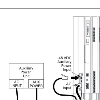
■ Installing the Auxiliary Power Unit 2-26
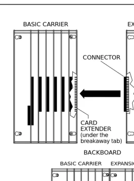
■ Installing Expansion Carriers 2-28
■ Installing the Processor 2-30
Installing the Processor in the Carrier 2-31
■ Installing the Modules 2-33
Guidelines 2-33
Installing Modules 2-34
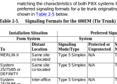
Tie Trunks 2-35
Tie Trunk Signaling 2-35
400EM (Tie Trunk) Module DIP Switches 2-36
Labeling 2-39
■ Replacing a Module 2-41
■ Connecting the Control Unit to an AC Outlet 2-44
■ Powering Up the System 2-45
■ Powering Down the System 2-46
3
Installing Telephones andAdjuncts 3-1
MERLIN LEGEND Communications System Release 5.0 Installation 555-650-140
Issue 1 June 1997 Contents
Page vi
Considerations 3-2
■ Installing Adjuncts 3-22
General Purpose Adapter 3-24
Dial Dictation Devices 3-25
Fax Machines 3-26
Group Calling Delay Announcement Devices 3-26
Credit Card Verification Terminals 3-27
Headsets 3-27
Loudspeaker Paging Systems 3-29
MERLIN Identifier 3-34
Modems 3-34
Music On Hold® and Magic on Hold 3-35
Supplemental Alerts 3-38
Unsupported Telephones, Adjuncts,
and Adapter 3-39
Single-Line Telephones 3-40
Single-Line Telephones in Release 3.0 and Later 3-42
■ Installing Direct Station Selectors 3-43
Considerations 3-43
■ Assembling MLX Telephones 3-48
Considerations 3-48
■ Installing Cordless or Cordless/Wireless Telephones 3-57
MDC 9000 Cordless Telephone 3-57
MDW 9000 Cordless/Wireless Telephones 3-57
■ Connecting Telephones to the Control Unit 3-58
Considerations 3-58
Wiring a Telephone for Two Voice Pairs 3-60
Contents
Page vii
4
Connecting the Control Unit to the Network Interface 4-1■ Wiring 4-2
RJ21X Interface 4-4
RJ11 and RJ14 Interfaces 4-10
RJ2GX Interface 4-11
RJ48C/X Interface 4-12
■ Testing Trunks 4-12
Testing Loop-Start Trunks 4-12
Testing Ground-Start Trunks 4-13
Testing NI-BRI Provisioning 4-14
■ Labeling Trunks 4-14
■ Installing the Channel Service Unit 4-15
ACCULINK CSUs 4-15
5
Installing the PC, CAT, or Printer 5-1■ Connecting a PC to the Control Unit 5-1
Connecting a PC Within 50 Feet 5-2
Connecting a PC More Than
50 Feet (15.2 m) Away 5-4
■ Connecting a CAT to the Control Unit 5-7
■ Connecting a Printer to the Control Unit 5-7
Connecting a CAT and Printer
on the Same AC Outlet 5-9
Connecting a CAT and Printer on a Different
AC Outlet 5-10
Connecting a Printer Within 50 Feet (15.2 m) 5-15
Connecting a Printer 50 Feet
(15.2 m) or More Away 5-17
MERLIN LEGEND Communications System Release 5.0 Installation 555-650-140
Issue 1 June 1997 Contents
Page viii
6
Connecting Data Equipment 6-1■ Data Stations 6-1
Modem Data Stations 6-3
Terminal Adapter Data Stations 6-4
■ Analog Voice and Modem Data Stations 6-5
GPA Settings 6-5
Setting Up 6-5
■ Modem Data-Only Stations 6-8
■ MLX Voice and Modem Data Stations 6-10
■ MLX Voice and Terminal Adapter Data Stations 6-12
Setting Up 6-12
■ Terminal Adapter Data-Only Stations 6-14
■ Video Conferencing Data Stations 6-17
Terminal Adapter and CSU Settings 6-21
7
Initializing and Testing the System 7-1■ Initializing the System 7-1
Programming Guides 7-2
Restoring from the Translation Memory Card 7-2
Restoring from the System
Programming Disk 7-2
■ Setting the Time and Date 7-3
■ Testing the System 7-3
Testing MLX Telephones 7-3
Testing MLX Display Telephones 7-5
Testing MLX Telephones with MFMs 7-5
Testing Telephones for Dial Tone 7-6
Contents
Page ix
Testing Analog Multiline and
Single-Line Telephones 7-7
Testing Ground-Start and Loop-Start Trunks
(Hybrid/PBX Systems Only) 7-8
Testing DID Trunks 7-8
Testing Tie Trunks 7-9
Testing BRI Trunks 7-12
Testing Selected System Features 7-12
Testing the DSS 7-15
Testing Night Service 7-15
Testing the Dictation System 7-16
Testing the Paging System 7-16
Testing Music On Hold 7-17
Testing the Power Failure Transfer Jacks 7-18
Testing Touch-Tone Receivers 7-19
■ Installing the Control Unit’s Housing 7-20
Installing the Top Cover 7-20
Installing the Front Cover 7-22
8
Installing Applications 8-1■ Voice Messaging Systems and Touch-Tone Receivers 8-2
Considerations 8-3
■ Automated Document
Delivery System 8-4
Considerations 8-4
Hardware Requirements 8-4
■ Call Accounting System 8-5
Considerations 8-5
Hardware and Software Requirements 8-6
MERLIN LEGEND Communications System Release 5.0 Installation 555-650-140
Issue 1 June 1997 Contents
Page x
■ Call Accounting Terminal 8-8
Considerations 8-8
Hardware Requirements 8-9
CAT Documentation 8-9
■ Call Management System 8-9
Considerations 8-10
Hardware and Software Requirements 8-11
CMS Documentation 8-12
■ CONVERSANT 8-12
Considerations 8-13
Hardware Requirements 8-13
CONVERSANT Intro Documentation 8-14
■ Integrated Solution III 8-14
Considerations 8-14
Hardware Requirements 8-15
■ Lucent Technologies Attendant 8-17
Considerations 8-17
Hardware Requirements 8-18
■ MERLIN MAIL 8-18
Considerations 8-19
Hardware Requirements 8-20
■ MERLIN PFC 8-21
Considerations 8-21
Hybrid/PBX and Key Modes 8-22
Behind Switch Mode 8-22
Hardware Requirements 8-23
■ PassageWay Direct
Contents
Page xi
Considerations 8-24
Hardware Requirements 8-24
■ System Programming and Maintenance (SPM) 8-25
Considerations 8-25
Hardware Requirements 8-26
■ Installing a CTI Link 8-27
New Installation 8-27
Link Reinstatement 8-29
9
Upgrading the System 9-1■ Upgrading to Release 5.0 9-1
■ Upgrading to Release 4.2 9-2
■ Upgrading to Release 4.1 9-2
■ Upgrading to Release 4.0 9-3
■ Backing Up System Programming 9-4
■ Removing the Control Unit Housing 9-6
■ Powering Down the System 9-8
■ Upgrading the Control Unit 9-10
Replacing the Housing Clips 9-13
■ Modifying the Processor
for Key Mode 9-15
■ Completing the Upgrade 9-19
■ Upgrading from the MERLIN II
Communications System 9-19
■ Replacing the Control Unit Housing 9-21
Release 2.0 or Earlier 9-21
A
System Numbering Forms A-1■ Form 2a, System Numbering:
MERLIN LEGEND Communications System Release 5.0 Installation 555-650-140
Issue 1 June 1997 Contents
Page xii
■ Form 2b, System Numbering:
Digital Adjuncts A-4
■ Form 2c, System Numbering: Line/Trunk Jacks A-5
■ Form 2d, System Numbering: Special Renumbers A-6
B
Unit Load Calculation Worksheet B-1■ Unit Load Worksheet B-2
GL
Glossary GL-1IMPORTANT SAFETY INSTRUCTIONS
Page xiii
IMPORTANT SAFETY INSTRUCTIONS
The exclamation point in an equilateral triangle is intended to alert the user to the presence of important operating and maintenance (servicing) instructions in the literature accompanying the product.
When installing telephone equipment, always follow basic safety precautions to reduce the risk of fire, electrical shock, and injury to persons, including:
■ Read and understand all instructions.
■ Follow all warnings and instructions marked on or packed with the
product.
■ Never install telephone wiring during a lightning storm.
■ Never install a telephone jack in a wet location unless the jack is
specifically designed for wet locations.
■ Never touch uninsulated telephone wires or terminals unless the
telephone wiring has been disconnected at the network interface.
MERLIN LEGEND Communications System Release 5.0
Installation 555-650-140 June 1997Issue 1
IMPORTANT SAFETY INSTRUCTIONS
Page xiv
■ Use only Lucent Technologies-manufactured MERLIN LEGEND®
Communications System circuit modules, carrier assemblies, and power units in the MERLIN LEGEND Communications System control unit.
■ Use only Lucent Technologies-recommended/approved MERLIN
LEGEND Communications System accessories.
■ If equipment connected to the analog extension modules (008, 408, 408
GS/LS) or to the MLX telephone modules (008 MLX, 408 GS/LS-MLX) is to be used for in-range out-of-building (IROB) applications, IROB protectors are required.
■ Do not install this product near water, for example, in a wet basement
location.
■ Do not overload wall outlets, as this can result in the risk of fire or
electrical shock.
■ The MERLIN LEGEND Communications System is equipped with a
3-wire grounding-type plug with a third (grounding) pin. This plug will fit only into a grounding-type power outlet. This is a safety feature. If you are unable to insert the plug into the outlet, contact an electrician to replace the obsolete outlet. Do not defeat the safety purpose of the grounding plug.
■ The MERLIN LEGEND Communications System requires a
supplementary ground.
■ Do not attach the power supply cord to building surfaces. Do not allow
anything to rest on the power cord. Do not locate this product where the cord will be abused by persons walking on it.
■ Slots and openings in the module housings are provided for ventilation.
To protect this equipment from overheating, do not block these openings.
■ Never push objects of any kind into this product through module
IMPORTANT SAFETY INSTRUCTIONS
Page xv
■ Unplug the product from the wall outlet before cleaning. Use a damp
cloth for cleaning. Do not use cleaners or aerosol cleaners.
■ Auxiliary equipment includes answering machines, alerts, modems, and
fax machines. To connect one of these devices, you must first have a Multi-Function Module (MFM).
■ Do not operate telephones if chemical gas leakage is suspected in the
area. Use telephones located in some other safe area to report the trouble.
!
WARNING:
!
■ For your personal safety, DO NOT install an MFM yourself.
■ ONLY an authorized technician or dealer representative shall install, set options, or repair an MFM.
■ To eliminate the risk of personal injury due to electrical shock, DO NOT attempt to install or remove an MFM from your MLX telephone. Opening or removing the module cover of your telephone may expose you to dangerous voltages.
New Features and Enhancements
Page xvi Release 4.1 Enhancements
MERLIN LEGEND Communications System Release 5.0 Installation
Issue 1 June 1997 MERLIN LEGEND Communications System Release 5.0
Installation 555-650-140
Issue 1 June 1997
New Features and Enhancements
Release 4.1 Enhancements
0
Release 4.1 includes all Release 4.0 functionality plus the enhancements listed below. There are no hardware changes in Release 4.1.
Coverage Timers Programmed for
Individual Extensions
0
Beginning with Release 4.1, coverage timers which control the duration of the delay before calls are sent to each level of coverage are changed as follows:
■ The Group Coverage Ring Delay (1–9 rings) is
programmed on individual extensions and replaces the Coverage Delay Interval programmed systemwide in previous releases.
■ The Primary Cover Ring Delay (1–6 rings) and Secondary Cover Ring Delay (1–6 rings) programmed on individual extensions replace the Delay Ring Interval programmed systemwide in previous releases.
New Features and Enhancements
Page xvii Release 4.1 Enhancements
Night Service with Coverage Control
0
Beginning with Release 4.1, a system manager can enable the Night Service Coverage Control option to automatically control the status of telephones programmed with Coverage VMS (Voice Mail System) Off buttons, according to Night Service status.
When Coverage Control is enabled and the MERLIN LEGEND Communications System is put into Night Service, all programmed Coverage VMS Off buttons are automatically turned off (LED is unlit) and all eligible outside calls are sent to the assigned voice messaging system calling group with normal ringing delay. When Night Service is deactivated during the day, all programmed Coverage VMS Off buttons are automatically turned on (LED is lit) and voice mail coverage is disabled for outside calls.
Users can override the Coverage VMS Off button status at any time by pressing the programmed Coverage VMS Off button to turn the LED on or off.
Night Service Group Line Assignment
0
Beginning with Release 4.1, a system manager can assign lines to Night Service groups to control handling of after-hours calls received on individual lines. This capability replaces the automatic Night Service group assignment of only lines that ring on the Night Service operator console. An outside line must be assigned to a Night Service group to receive Night Service treatment.
MERLIN LEGEND Communications System Release 5.0
Installation 555-650-140 June 1997Issue 1
New Features and Enhancements
Page xviii Release 4.1 Enhancements
Forward on Busy
0
Beginning with Release 4.1, the Forward, Follow Me and Remote Call Forward features are enhanced to remove the requirement that a call must be ringing at an extension before it can be forwarded. With the Forward on Busy
enhancement, a call to an extension with no available SA (System Access) or
ICOM (Intercom) buttons is forwarded immediately to the programmed
destination, preventing the caller from hearing a busy signal from the intended call recipient’s extension.
Maintenance Testing for BRI Facilities
That Are Part of Multiline Hunt Groups
(MLHGs)
0
Beginning with Release 4.1, the NI-1 BRI (National Integrated Services Digital Network-1 Basic Rate Interface) Provisioning Test Tool is enhanced to include testing for BRI facilities that are part of Multiline Hunt Groups (MLHGs).
The NI-1 BRI Provisioning Test Tool is used by Lucent Technologies
maintenance personnel on MERLIN LEGEND Communications Systems that include a 800 NI-BRI module. Technicians use the tool during system
New Features and Enhancements
Page xix Release 4.2 Enhancements
Release 4.2 Enhancements
0
Release 4.2 includes all Release 4.1 functionality plus the enhancements listed below. There are no hardware changes for Release 4.2.
Additional Network Switch Interface and Services
Options for ISDN Primary Rate Interface (PRI)
0
Release 4.2 of the system supports connectivity to MCI® or local exchange
carrier (LEC) PRI services and to the following central office switch types (in addition to the 4ESS™ and 5ESS® switch types that are currently available for
AT&T Switched Network services):
■ Nortel® DMS™-100 BCS 36 for local exchange carrier
services
■ Nortel DMS-250 generic MC107 serving the MCI network
MERLIN LEGEND Communications System Release 5.0
Installation 555-650-140 June 1997Issue 1
New Features and Enhancements
Page xx Release 4.2 Enhancements
Beginning with Release 4.2, the following MCI PRI and PRI local exchange carrier (LEC) services (along with the AT&T Switched Network Services), can be provided to users of the MERLIN LEGEND Communications System:
■ MCI Toll Services for DMS-250 or DEX600E switch type:
— MCI Prism® service for domestic outgoing long-distance and
international voice calls; for domestic outgoing 56-kbps restricted, 64-kbps unrestricted, and 64-kbps restricted circuit-switched data calls
— MCI VNet® service for incoming and outgoing, domestic and
voice calls; for 56-kbps restricted, 64-kbps restricted, and 64-kbps unrestricted circuit-switched data calls
— MCI 800 for domestic toll-free incoming voice calls
— MCI 900 service numbers
■ LEC services for DMS-100 switch types:
— DMS Virtual Private Network service for calls between the MERLIN LEGEND Communications system and another communications system (such as another MERLIN LEGEND Communications System)
— DMS INWATS (Inward Wide Area Telephone Service) for domestic toll-free incoming voice calls
— DMS OUTWATS (Outward Wide Area Telephone Service) for domestic outgoing long-distance voice calls
— DMS FX (foreign exchange) to provide local call rating for calls from the local exchange to the area serviced by the foreign exchange.
New Features and Enhancements
Page xxi Release 4.2 Enhancements
Improvements to Station Message Detail
Recording (SMDR) and Support for
MERLIN LEGEND Reporter Application
0
The SMDR feature is enhanced to provide more details about calling group agent activities and help system managers assess the effectiveness of call centers, in terms of both agent performance and the adequacy of facilities to handle inbound calls. These improvements apply to calling groups that are programmed as Auto Login or Auto Logout type. The SMDR and MERLIN LEGEND Reporter features listed are administrable:
■ TALK Field. for Auto Login and Auto Logout calling groups, the
TALK field records the amount of time a calling group agent spends on a call.
■ DUR. (DURATION) Field. For Auto Login and Auto Logout
calling groups, call timing begins when a call arrives at MERLIN LEGEND Communications System and not after a preset number of seconds. Call timing ends when the call is disconnected; either the caller or the agent hangs up. This allows the system manager to determine how long a caller waited for an agent’s attention.
■ Coding of Calls on Reports. An asterisk (*) appears in the call
record when:
a. A call is not answered by an Auto Login or Auto Logout calling group agent and is abandoned while waiting for an agent.
b. The call is answered by someone not a member of an Auto Login or Auto Logout calling group.
MERLIN LEGEND Communications System Release 5.0
Installation 555-650-140 June 1997Issue 1
New Features and Enhancements
Page xxii Release 4.2 Enhancements
MERLIN LEGEND Reporter
0
MERLIN LEGEND Reporter provides basic call accounting system reports for all incoming calls to Auto Login or Auto Logout type calling groups. MERLIN LEGEND Reporter assists in determining the effectiveness of calling group agents, assessing the level of service provided to callers, and ascertaining whether adequate incoming phone lines and agents are available to handle peak call load. MERLIN LEGEND Reporter is an administrable option. The default is Off, in which case the Release 4.0 SMDR reports are available. If this options is set to On, the following reports are provided:
■ Organization Detail Report
■ Organization Summary and Trends Report
■ Selection Detail Report
■ Account Code Report
■ Traffic Report
■ Extension Summary Report
■ Data Report
■ Talk and Queue Time Distribution Report
■ Time of Day Report
■ ICLID Call Distribution Report
■ Facility Grade of Service Report
Maintenance Enhancements
0
Change to Permanent Error Alarm
0
New Features and Enhancements
Page xxiii Release 5.0 Enhancements
Enhanced Extension Information Report
0
Beginning with Release 4.2, the Extension Information Report includes the Extension Status (ESS) and supervisory mode of each extension.
Release 5.0 Enhancements
0
Release 5.0 includes all Release 4.2 functionality plus the enhancements listed below.
Computer Telephony Integration (CTI)
0
Beginning with Release 5.0, a PassageWay® Telephony Services CTI link from
the MERLIN LEGEND Communications System to a LAN server running Novell® NetWare® software allows Lucent Technologies-certified telephony
applications to control MLX and analog multiline telephone (BIS only). The physical connection for the CTI link is an MLX port on a 008-MLX or 408-MLX module on the MERLIN LEGEND Communications System control unit and an ISDN link interface card plugged into the customer’s server. The feature is available for Hybrid/PBX mode systems only.
NOTE:
The NetWare Server software version must be 3.12, 4.1, or 4.11.
MERLIN LEGEND Communications System Release 5.0
Installation 555-650-140 June 1997Issue 1
New Features and Enhancements
Page xxiv Release 5.0 Enhancements
Basic Call Control
0
A CTI link application on a user’s computer can assume basic call control of the user’s analog multiline or MLX telephone’s SA buttons. Basic call control includes:
■ Answering calls arriving on an SA button
■ Making calls from an SA button
■ Hanging up calls
■ Hold and retrieving a call on hold at the user’s extension
■ Conference calls from a DLC or QCC operator
NOTE:
Transfer and 3-way conference, when handled through a CTI link application, provide the original caller’s calling number information or other information to transfer receiver or new conference participant, if the user has screen-pop capability
Screen Pop
0
New Features and Enhancements
Page xxv Release 5.0 Enhancements
Screen pop can occur on incoming calls from the following sources:
■ Calling group distribution
■ ISDN PRI Routing by Dial Plan
■ An extension on the MERLIN LEGEND Communications System
■ Remote access
NOTE:
In the case of remote access calls, the only information that the application can collect about the caller is the remote telephone number.
■ A transfer of a call that was answered by a voice response unit
■ A transfer, redirection, or conference of a call that was answered at a DLC or at a QCC
NOTES:
1. DLCs (Direct-Line Consoles) may use CTI applications. If they do, they perform the same way as other extensions. A DLC assigned to use a CTI link application is a monitored
DLC. When a DLC is used as a regular operator console and not assigned as a CTI link extension, it is non-monitored.
2. Calls to a QCC or non-monitored DLC do not initiate screen pop at the operator position, but when an operator directs a call to an extension using a CTI application, caller information does initiate screen pop.
MERLIN LEGEND Communications System Release 5.0
Installation 555-650-140 June 1997Issue 1
New Features and Enhancements
Page xxvi Release 5.0 Enhancements
HotLine Feature
0
The Release 5.0 HotLine feature is designed for retail sales, catalogue sales, and other types of businesses and organizations and is available in all three modes of system operation. It allows a system manager to program a single-line telephone extension connected to an 008_OPT, 012, or 016 moduel as a HotLine. When a user lifts the handset at the HotLine extension, the telephone automatically dials the inside extension or outside telephone number
programmed as the first Personal Speed dial number (code #01) for the extension. The system does not permit calls to be transferred, put on hold, or conferenced. (a user can press the telephone’s Hold button, if it has one, to put a call on local hold, but the call cannot be redirected in any way. Switchhook flashes are ignored.)
Personal Speed Dial codes can be programmed from the extension prior to HotLine assignment (a system programming function). Alternatively, a Personal Speed Dial code can be programmed from the single-line telephone after HotLine operation is assigned. However, because of security considerations, this is a one-time opportunity. Once the Personal Speed Dial number is programmed, any changes to it or any other extension programming must be performed using centralized telephone programming.
Any type of inside or outside line that is normally available to a single-line telephone can be assigned to a HotLine extension. Generally, the HotLine telephone does not receive calls, and its lines should be set to No Ring.
SECURITY
l
ALERT:
!
New Features and Enhancements
Page xxvii Release 5.0 Enhancements
Group Calling Enhancements
0
Release 5.0 and later systems include Group Calling features that enhance call center operations.
Most Idle Hunt Type
0
In addition to the Circular (factory setting) and Linear hunt types supported in earlier releases, a third hunt type distributes calling group calls in an order based on which agent has waited the longest since transferring or hanging up on an incoming calling group call. For some applications, this hunt type is more efficient than the circular type because it takes into account the varying duration of calls. The system distributes calls based on when an agent last completed a call, not on when he or she last received one. This hunting method ignores non-calling group calls. For example, if an agent transfers a call that arrived on a line not assigned to the calling group, the calling group member’s most-idle status is unaffected.
Delay Announcement Devices
0
The system manager can designate as many as ten primary delay
announcement devices per group rather than the single device for each group that is available in Release 4.2 and earlier systems. Furthermore, an additional secondary delay announcement device can be specified, for a total of ten primary device extensions and one secondary device extension per group.
MERLIN LEGEND Communications System Release 5.0
Installation 555-650-140 June 1997Issue 1
New Features and Enhancements
Page xxviii Release 5.0 Enhancements
The primary and secondary announcement options, when used together, allow an initial message to play for callers, followed by a repeating announcement that, for example, urges callers to stay on the line and wait for a calling group member.
Two or more groups may share an announcement device.
A primary delay announcement device can be administered as a secondary delay announcement device.
Enhanced Calls-in-Queue Alarm
Thresholds
0
Three Calls-in-Queue Alarm thresholds can be set to more clearly indicate the real-time status of the queue according to the behavior of programmed Calls-in-Queue Alarm buttons. In earlier releases, only one Calls-in-Queue Alarm Threshold setting is available to activate the LEDs at programmed Calls-in-Queue Alarm buttons for a calling group.
Using all three levels, the system manager sets Threshold 1 to the lowest value, Threshold 2 to a middle value, and Threshold 3 to the highest value. A
Calls-in-Queue Alarm button indicates the severity of the alarm conditions in the following ways:
■ If the number of Waiting calls is less than the value programmed for Threshold 1 or drops below that level, the LED is unlit.
■ If the number of waiting calls is greater than or equal to the Threshold 1 value but less than the Threshold 2 value, the LED flashes.
■ If the number of waiting calls is greater than or equal to the Threshold 2 value but less than the value for Threshold 3, the LED winks.
New Features and Enhancements
Page xxix Release 5.0 Enhancements
NOTE:
A DSS (Direct Station Selector) button that is used as a Calls-in-Queue Alarm button can only indicate two
threshold levels, either by flashing or by lighting steadily. If a calling group must use this type of Calls-in-Queue Alarm button, only two threshold levels should be programmed.
If all three thresholds are set to the same value, the result is one threshold only (steady) with LED state either off or on. If two values are the same, then the result is two alarm levels (flash, steady). The factory setting is one call for all three thresholds with LED states of off, flash, and steady.
An external alert only signals when the number of calls in the queue exceeds the programmed Threshold 3 value.
MLX-5 and MLX-5D Telephones
0
The MLX-5 nondisplay and the MLX-5D display telephones are compatible with all system releases. The display telephone includes a 2-line by 24-character display, and both telephones come with 5 line buttons. In systems prior to Release 5.0, the MLX-5 and MLX-5D telephones are treated as MLX-10 and MLX-10D telephones respectively. As of Release 5.0, the system recognizes the MLx-5 and MLX-5D telephones as 5-button telephones.
If these telephones are connected to communications system releases prior to 5.0, they are recognized by the communications system as 10 button
Prior Releases Features and Enhancements
Page xxx Release 3.1 Enhancements
MERLIN LEGEND Communications System Release 5.0 Installation
Issue 1 June 1997 MERLIN LEGEND Communications System Release 5.0
Installation 555-650-140
Issue 1 June 1997
Prior Releases Features and Enhancements
Release 3.1 Enhancements
Release 3.1 includes all Release 3.0 functionality plus the enhancements listed below.
■ Call Restriction checking for star codes
Beginning with Release 3.1, the system manager can now add star (*) codes to Allowed and Disallowed Lists to help prevent toll fraud. Star codes, typically dialed before an outgoing call, enable telephone users to obtain special services provided by the central office (CO). For example, in many areas, a telephone user can dial *67 before a telephone number to disable central office-supplied caller identification at the receiving party’s telephone. (You must contract with your telephone service provider to have these codes activated.)
Prior Releases Features and Enhancements
Page xxxi Release 3.1 Enhancements
■ Trunk-to-Trunk Transfer on a per-station basis
This enhancement to the trunk-to-trunk feature enables the system manager to allow or disallow trunk-to-trunk transfer on a per-station basis. Beginning with Release 3.1, the default setting for all stations is restricted.
■ Programmable Second Dial Tone Timer
Beginning with Release 3.1, the system manager can now assign a second dial tone timer to lines and trunks to help prevent toll fraud (for example, when star codes are used). After receiving certain digits dialed by a user, the CO may provide a second dialtone, prompting the user to enter more digits. If this second dial tone is delayed, and the user dials digits before the CO provides the second dial tone, there is a risk of toll fraud or misrouting of the call. The second dial tone timer enables the system manager to make sure that the CO is ready to receive more digits from the caller.
■ A Disallowed List containing numbers frequently associated with
toll fraud
Beginning with Release 3.1, Disallowed List #7 now contains default entries, which are numbers frequently associated with toll fraud. By default, Disallowed List #7 is automatically assigned to both generic and integrated VMI ports used by voice messaging systems. The system manager must manually assign this list to other ports.
■ Pool Dial-Out Code restriction for all extensions by default
MERLIN LEGEND Communications System Release 5.0
Installation 555-650-140 June 1997Issue 1
Prior Releases Features and Enhancements
Page xxxii Release 3.1 Enhancements
■ Outward restrictions for VMI ports by default
Beginning with Release 3.1, ports assigned for use by voice messaging systems (generic or integrated VMI ports) are now assigned outward restrictions by default. If a voice messaging system should be allowed to call out (for example, to send calls to a user’s home office), the system manager must remove these restrictions.
Before removing restrictions, it is strongly recommended that you read “Appendix A: Customer Support Information.”
■ New default Facility Restriction Level (FRL) for VMI ports
Beginning with Release 3.1, the default FRL for VMI ports has changed to 0, restricting all outcalling.
■ New default for the Default Local Route Table
Beginning with Release 3.1, the default FRL has changed to 2 for the Default Local Route Table. Now, system managers can easily change an extension default of 3 to 2 or lower in order to restrict calling. No
adjustment to the route FRL is required.
■ New maintenance procedure for testing outgoing trunk problems
A password is now required for technicians to perform trunk tests.
Prior Releases Features and Enhancements
Page xxxiii Release 4.0 Enhancements
Release 4.0 Enhancements
Release 4.0 includes all Release 3.1 functionality plus the enhancements listed below:
■ Support for up to 200 stations
Release 4.0 has an expanded dial plan that supports up to 200 tip/ring devices.
■ New 016 tip/ring module
This new module supports the 200 station dial plan by providing 16 ports for tip/ring devices. Applications that use a tip/ring interface can connect to this board. All 16 ports can ring simultaneously. Four touch-tone receivers (TTRs) are included on the module as well. The module’s ringing frequency (default 20 Hz) can be changed through programming to 25 Hz for those locations that require it.
■ Support for National ISDN BRI Service
This service provides a low-cost alternative to loop-start and ground-start trunks for voice and digital data connectivity to the Central Office. Each of the two B (bearer)- channels on a BRI line can carry one voice and one data call at any given time. The data speeds on a B-channel are up to 14.4 kbps for analog data and up to 64 kbps for digital data, which is necessary for video conferencing and other video applications. Release 4.0 supports the IOC Package “S” (basic call handing) service
configuration and Multi-Line Hunt service configuration on designated CO switches.
■ New 800 NI-BRI module
MERLIN LEGEND Communications System Release 5.0
Installation 555-650-140 June 1997Issue 1
Prior Releases Features and Enhancements
Page xxxiv Release 4.0 Enhancements
■ Support for 2B Data applications
Release 4.0 has certified group and desktop video applications that use two B-channels to make video/data calls from endpoints (stations) that are enabled to use 2B Data. The endpoints that support these
applications connect to an MLX-port on the MERLIN LEGEND system. 2B Data applications can make use of the NI-1 BRI, PRI, or T1 Switched 56 network interfaces to make outside connections using one or two data channels at a time.
■ Support for T1 digital data transmission
Release 4.0 expands its T1 functionality by providing access to digital data over the public-switched 56 kbps network in addition to data Tie-Trunk services. Users who have T1 facilities for voice services can now use them for video calls at data rates of 56 kbps per channel (112 kbps for video calls using two channels). The Release 4.0 offering also includes point-to-point connectivity over T1 Tie-trunks, allowing
customers to connect two MERLIN LEGEND Communications Systems
or a MERLIN LEGEND Communications System with a DEFINITY®
Communications System or DEFINITY Communications Server. The two communications systems can be co-located or off-premises.
■ Delayed Call Forwarding
Prior Releases Features and Enhancements
Page xxxv Release 4.0 Enhancements
■ Voice Announce on the QCC
The Queued Call Console (QCC) operator can enable the fifth Call Button to announce a call on another user’s speakerphone if the destination telephone has a Voice Announce-capable SA button available. A QCC cannot receive Voice Announce calls; they are
received as ringing calls. The factory-set status for the fifth Call Button is to have Voice Announce disabled.
■ Time-based option for overflow on Calling Group
Release 4.0 has added a time limit for calls in queue in addition to the previous number limit. If the Overflow Threshold Time is set to a valid number between 1–900 seconds, calls that remain in the Calling Group Queue for the set time are sent to the Overflow Receiver. If the Overflow Threshold Time is set to 0, Overflow by time is turned off. The factory-set time limit is 0 seconds (Overflow by time off).
■ Downloadable Firmware for the 016 T/R board and the NI-BRI board
The Personal Computer Memory Card International Association (PCMCIA) technology introduced in Release 3.0 continues to support these two new boards in Release 4.0 for installation and upgrade. A Release 3.0 or later processor is required for PCMCIA technology.
■ Single-Line Telephone Enhancements
— Disable Transfer. Through centralized telephone programming, the system manager can disable the ability to transfer calls by removing all but one SA or ICOM button from the telephone.
MERLIN LEGEND Communications System Release 5.0
Installation 555-650-140 June 1997Issue 1
Prior Releases Features and Enhancements
Page xxxvi Release 4.0 Enhancements
— Forward Disconnect. All ports on 012 and 016 modules now send forward disconnect to all devices connected to them when forward disconnect is received from the CO. This enhancement prevents the trunk/line from being kept active when one end disconnects from the call. If an answering machine is connected to the port, it will not record silence, or busy tones, or other useless messages. This is a non-administrable operation.
■ 7-digit password for SPM
About This Book
Page xxxvii Intended Audience
About This Book
The MERLIN LEGEND Communications System is an advanced digital switching system that integrates voice and data communications features. Voice features include traditional telephone features, such as Transfer and Hold, and advanced features, such as Group Coverage and Park. Data features allow both voice and data to be transmitted over the same system wiring.
Intended Audience
MERLIN LEGEND Communications System Release 5.0
Installation 555-650-140 June 1997Issue 1
About This Book
Page xxxviii How to Use This Book
How to Use This Book
This book provides step-by-step procedures for isolating troubles both inside and outside the communications system. Refer to the chapter associated with the reported problem to start the troubleshooting procedure.
Refer to the following documentation for additional information:
■ Equipment and Operations Reference provides detailed information on
system hardware, telephones, and other equipment. (Not updated since Release 3.0.)
■ Feature Reference provides details on the features of the
communications system.
■ System Planning provides procedures and forms for planning a system
for installation.
■ System Programming gives procedural instructions for programming
system features.
■ Users’ guides and Operators’ Guides give procedural instructions for
programming and using telephone features.
“Related Documents,” later in this section, provides a complete list of system documentation together with ordering information.
In the USA only, Lucent Technologies provides a toll-free customer Helpline (1
800 628-2888) 24 hours a day. Call the Helpline, or your Lucent Technologies representative, if you need assistance when installing, programming, or using your system.
Terms and Conventions Used
About This Book
Page xxxix Terms and Conventions Used
Lines, Trunks and Facilities
Facility is a general term that designates a communications path between a telephone system and the telephone company central office. Technically a trunk
connects a switch to a switch, for example the MERLIN LEGEND
Communications System to the central office. Technically, a line is a loop-start facility or a communications path that does not connect two switches (for example, an intercom line or a Centrex line). However, in actual usage, the terms line and trunk are often applied interchangeably. In this book, we use
line/trunk and lines/trunks to refer to facilities in general. Specifically, we refer to
digital facilities. We also use terms such as personal line, ground-start trunk, Direct Inward Dialing (DID) trunk, and so on. When you talk to your local telephone company central office, ask them which terms they use for the specific facilities they connect to your system.
Some older terms have been replaced with newer terms. The following list shows the old term on the left and the new term on the right:
trunk module line/trunk module
trunk jack line/trunk jack
station extension
station jack extension jack
analog data station modem data station
digital data station terminal adapter
7500B data station terminal adapter
analog voice and analog data station analog voice and modem data digital voice and analog data station MLX voice and modem data
analog data only station modem data only station
digital data only station terminal adapter only station
7500B data only station terminal adapter only station
digital voice and digital data station MLX voice and terminal adapter station
MLX voice and 7500B data station MLX voice and terminal
MERLIN LEGEND Communications System Release 5.0
Installation 555-650-140 June 1997Issue 1
About This Book
Page xl Terms and Conventions Used
Typographical Conventions
Certain type fonts and styles act as visual cues to help you rapidly understand the information presented:
Example Purpose
It is very important that you follow these steps. You must attach the wristband before touching the connection.
Italics indicate emphasis.
The part of the headset that fits over one or both ears is called a
headpiece.
Italics also set off special terms.
If you press the Feature button on an MLX display telephone, the display lists telephone features you can select. A programmed Auto Dial button gives you instant access to an inside or outside number.
The names of fixed-feature,
factory-imprinted buttons appear in bold. The names of programmed buttons are printed as regular text.
Choose Ext Prog from the display screen.
Plain constant-width type indicates text that appears on the telephone display or personal computer (PC) screen.
About This Book
Page xli Product Safety Labels
Product Safety Labels
Throughout these documents, hazardous situations are indicated by an exclamation point inside a triangle and the word CAUTION or WARNING.
!
WARNING:
!
Warning indicates the presence of a hazard that could cause death or severe personal injury if the hazard is not avoided.
!
CAUTION:
MERLIN LEGEND Communications System Release 5.0
Installation 555-650-140 June 1997Issue 1
About This Book
Page xlii Security
Security
Certain features of the system can be protected by passwords to prevent unauthorized users from abusing the system. You should assign passwords wherever you can and limit knowledge of such passwords to three or fewer people.
Nondisplaying authorization codes and telephone numbers provide another layer of security. For more information, see Appendix A, “Customer Support Information” following Maintenance and Troubleshooting.
Throughout this document, toll fraud security hazards are indicated by an exclamation point inside a triangle and the words Security Alert.
!
Security Alert:
Security Alert indicates the presence of atoll fraud security hazard. Toll fraud is the unauthorized use of your telecommunications system by an unauthorized party (for example, persons other than your
About This Book
Page xliii Related Documents
Related Documents
In addition to this book, the documents listed below are part of the
documentation set. Within the continental United States, these documents can be ordered from the Lucent Technologies GBCS Publications Fulfillment Center by calling 1 800 457-1235.
Document No. Title
System Documents
555-650-110 Feature Reference
555-650-111 System Programming
555-650-112 System Planning
555-650-113 System Planning Forms
555-650-116 Pocket Reference
555-650-118 System Manager’s Guide
Telephone User Support
555-650-122 MLX-5D™, MLX-10D™, MLX-10DP™, MLX-28D™, and
MLX-20L™ Display Telephones User’s Guide
555-630-150 MLX- 5D, MLX-10D and MLX-10DP Display Telephone
Tray Cards (5 cards)
555-630-153 MLX-28D and MLX-20L Telephone Tray Cards (5 cards)
555-650-124 MLX-10™ Nondisplay Telephone User’s Guide
555-630-151 MLX-5™ and MLX-10 Nondisplay Telephone Tray Cards
(6 cards)
555-630-155 MLX-16DP Display Telephone Tray Cards (5 cards)
555-650-120 Analog Multiline Telephones User’s Guide
555-650-126 Single-Line Telephones User’s Guide
MERLIN LEGEND Communications System Release 5.0
Installation 555-650-140 June 1997Issue 1
About This Book
Page xliv How to Comment on This Document
How to Comment on This Document
We welcome your comments, both positive and negative. Please use the feedback form on the next page to let us know how we can continue to serve you. If the feedback form is missing, write directly to:
Documentation Manager Lucent Technologies 211 Mount Airy Road Room 2W226
Basking Ridge, NJ 07920
Document No. Title
System Operator Support
555-640-134 MLX Direct-LIne Consoles Operator’s Guide
555-640-132 Analog Direct-Line Consoles Operator’s Guide
555-650-136 MLX Queued Call Console Operator’s Guide
Miscellaneous User Support
555-650-130 Calling Group Supervisor’s Guide
555-650-105 Data and Video Reference
555-650-136 MLX Queued Call Console Operator’s Guide
Documentation for Qualified Technicians
555-650-140 Installation, Programming & Maintenance (IP&M) Binder [consists of Installation, System Programming &
Maintenance (SPM), Maintenance & Troubleshooting]
Toll Fraud Security
Introduction
Page 1-1 Installation Sequence
1
1
Introduction
Installation of the MERLIN LEGEND Communications System involves the following:
■ Installing the control unit ■ Installing the telephones ■ Connecting system wiring ■ Installing optional equipment
This chapter provides an overview of the installation process, which varies from customer to customer.
Installation Sequence
The following is a list of the components that the system can include and shows the order in which you should install them. When installing your customer’s system, try to adhere to this order as much as possible:
1. Install the control unit (required).
2. Connect power accessories to the control unit (optional).
3. Install the telephones (required) and adjuncts (optional).
MERLIN LEGEND Communications System Release 5.0
Installation 555-650-140 June 1997Issue 1
Introduction
Page 1-2 System Forms
5. Connect the control unit to the network interface (required).
6. Connect the channel service unit (CSU) to the 100D module on the control unit (required only with the 100D module).
7. Connect the printer and PC to the control unit (optional).
8. Connect data equipment to the control unit (optional).
9. Initialize and test the system (required).
10. Install the control unit housing (required).
11. Install applications (optional).
A list of required tools and equipment is given before each installation procedure.
System Forms
Some of the installation procedures in this guide refer to system forms. These forms indicate information that is specific to your customer’s system. The forms you need should be included with the system programming disk or memory card, which contains all of the programming specifically for your customer’s system.
If you are upgrading an existing system and do not have the required forms for your customer’s system, you can load System Programming and Maintenance (SPM) and print out the required forms.
If you find that you do not have a completed set of system forms for your customer’s system, contact your technical support organization or the Customer Service Center (CSC). See the inside front cover for telephone numbers.
Introduction
Page 1-3 System Forms
Installing the Control Unit
■ Form 1, System Planning. Some procedures in Chapter 2, ‘‘Installing
the Control Unit’’, refer to the Control Unit Diagram, which is printed on the reverse side of this form.
■ Form 3c, Incoming Trunks: Tie. If you install a 400EM module in the
control unit, use this form to determine the appropriate switch settings prior to installation.
Installing Telephones (Required)
and Adjuncts (Optional)
The following forms indicate the telephones and adjuncts that you must install:
■ Form 2a, System Numbering: Extension Jacks
■ Form 2b, System Numbering: Digital Adjuncts ■ Form 4b, Analog Multiline Telephone
■ Form 4d, MLX Telephone
■ Form 4e, MFM Adjunct: MLX Telephone
■ Form 4f, Tip/Ring Equipment
■ Form 5a, Direct-Line Console (DLC): Analog ■ Form 5b, Direct-Line Console (DLC): Digital
■ Form 5c, MFM Adjunct: DLC
MERLIN LEGEND Communications System Release 5.0
Installation 555-650-140 June 1997Issue 1
Introduction
Page 1-4 Programming the System
Connecting the Network Interface
The following forms indicate the trunks that you must connect to the control unit. Information regarding the channel service unit (CSU) is included on these forms.
■ Form 2c, System Numbering: Line/Trunk Jacks
■ Form 3a, Incoming Trunks: Remote Access
■ Form 3b, Incoming Trunks: DS1 Connectivity (100D Module)
■ Form 3d, Incoming Trunks: DID
Connecting Data Equipment
The following forms indicate the data equipment you will need to set up data stations.
■ Data Form 1a, Modem Data Station
■ Data Form1b, 7500B Data Station
■ Data Form 2, Data Hunt Groups
Programming the System
If you have a system programming disk created with SPM or a Translation memory card, you do not need to program the system. Instead, you can use the disk or memory card to restore the system; see Chapter 7, ‘‘Initializing and Testing the System’’, for instructions. If you did not receive a disk or a memory card and it is your responsibility to program the system, see System
Introduction
Page 1-5 Upgrading the System
Upgrading the System
If you are upgrading to Release 5.0 from Release 4.2, 4.1, 3.1, 3.0, 2.1, 2.0, 1.0, 1.1, or from the MERLIN® II Communications System, refer to Chapter 9, ‘‘Upgrading the System’’, then Chapter 7, ‘‘Initializing and Testing the System’’, for upgrade instructions.
NOTE:
Installing the Control Unit
Page 2-1 Overview
MERLIN LEGEND Communications System Release 5.0 Installation
Issue 1 June 1997 MERLIN LEGEND Communications System Release 5.0
Installation 555-650-140
Issue 1 June 1997
2
2
Installing the Control Unit
If you have not read Chapter 1, ‘‘Introduction’’, do so before continuing with this chapter.
Overview
Installing the control unit involves the following procedures:
■ Preparation requirements ■ Installing the backboard
■ Meeting the power and grounding requirements ■ Checking the total unit load
■ Installing the basic carrier ■ Installing any expansion carriers ■ Installing the power supply ■ Installing the processor
■ Installing the line/trunk and extension modules ■ Connecting the control unit to AC power
■ Powering up the system
■ Powering down the system
Installing the Control Unit
Page 2-2 Overview
Environment
The control unit must be installed on a backboard. The placement of the backboard, and the control unit on it, requires careful consideration. Make sure you install the backboard in an area that meets all of the environmental
requirements listed in Table 2-1.
!
WARNING:
!
Do not install the control unit outdoors.
Table 2-1. Environmental Requirements
Operating Temperatures
40o–104oF (4o–40oC)
Optimal temperature: 60oF (15.6oC)
Humidity 20%–80%
Airborne Contamination
Do not expose the control unit to moisture, corrosive gases, dust, chemicals, spray paint, or similar material.
Ventilation Allow at least 1 in. (2.54 cm) on the right and left sides of the
control unit and at least 12 in. (30.48 cm) above and below it to prevent overheating.
Do not place the control unit near extreme heat sources (for example: furnaces, heaters, attics, or direct sunlight).
Electrical Fields Do not expose the control unit to devices that generate
electrical currents causing interference (such as arc welders or motors).
Heat Dissipation
Basic carrier: 500 Btu/hr
MERLIN LEGEND Communications System Release 5.0
Installation 555-650-140 June 1997Issue 1
Installing the Control Unit
Page 2-3 Overview
Electrical Noise/Radio-Frequency Interference
In most cases, electrical noise is introduced into the system through trunk or telephone cables. However, electromagnetic fields near the control unit can also cause noise in the system. Therefore, you should not place the control unit and cable runs in areas where a high electromagnetic field strength exists.
Radio transmitters (AM and FM), television stations, induction heaters, motors (with commutators) of 0.25 horsepower (200 watts) or greater, and similar equipment are leading causes of radio-frequency interference (RFI). Small tools with universal motors are generally not a problem when they operate on separate power lines. Motors without commutators generally do not cause interference.
Field strengths below 1.0 volt per meter are unlikely to cause interference. To estimate the field strength produced by radio transmitters, divide the square root (√) of the emitted power, in kilowatts, (÷) by the distance from the antenna in kilometers which equals (=) the field strength in volts per meter.
Installing the Control Unit
Page 2-4 Overview
Control Unit Requirements
■ Dimensions
— Basic carrier: 14 in. wide by 23 in. high by 12 in. deep
— Basic carrier and one expansion carrier: 25 in. wide by 23 in. high by 12 in. deep
— Basic carrier and two expansion carriers: 37 in. wide by 23 in. high by 12 in. deep
■ Location
— Within 5 ft. (152 cm) of an AC power outlet that is not
switch-controlled
— Within 25 ft. (762 cm) of the network interface, or use an Off-Premises Range Extender (OPRE)
— Within 1000 cable ft. (305 m) of telephones, or use an OPRE (for basic telephones)
!
CAUTION:
The AC outlet for the control unit cannot be switch-controlled. Plugging the control unit into such an outlet invites accidental disconnection of the system.
Hardware Preassembly Process
MERLIN LEGEND Communications System Release 5.0
Installation 555-650-140 June 1997Issue 1
Installing the Control Unit
Page 2-5 Overview
Backboard Requirements
The backboard should be wide enough to accommodate the carrier and up to two additional carriers, assuming that system growth is anticipated. There should be enough room on each side of the control unit for the necessary wiring fields.
To accommodate the maximum control unit size, make sure the backboard meets the following requirements:
■ Material
—
¾
-inch plywood— Check with the local building code enforcement agency to see whether fire-retardant material is required.
— Make sure that the material meets local building codes.
■ Dimensions
— With Systimax wiring: 7 ft. wide by 4 ft. high
— Without Systimax wiring: 6 ft. wide by 3 ft. high
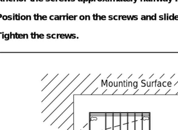
Installing the Backboard
When you are certain that the backboard meets the requirements indicated above, or is the new lightweight plastic material backboard with preassembled equipment in place, attach the backboard to the wall.
Use the following mounting hardware:
■ For a wood mounting surface, use wood screws.
■ For brick, cinderblock, or concrete, use masonry anchors. ■ For plaster or plasterboard, use toggle bolts.
■ For sheet metal, use sheet-metal screws and attach them to the
Installing the Control Unit
Page 2-6 AC Power and Grounding
NOTE:
The mounting hardware should resist a combined pullout force of at least 650 pounds (295 kilograms).
AC Power and Grounding
Proper power and grounding are essential for the system to run correctly and safely.
!
CAUTION:
If any of the following requirements are not met, the customer must contact a licensed electrician. Do not install the system until all requirements are met.
Verify that all of the following power and grounding requirements are met:
■ The load center of appropriate current rating must be equipped with
circuit breaker(s) labeled 120 V AC, 15 amps.
■ Each breaker must protect one dedicated quad AC outlet or two
dedicated duplex AC outlets.
■ All AC outlets must connect to the same load center and the ground wire
must connect to the single-point ground bar on the first AC outlet (see Figure 2-1).
■ One outlet must have an attached ground bar connected by a #6 AWG
copper wire to an approved ground (see ‘‘Approved Grounds’’, later in this chapter, for a description of approved grounds). This ground bar is the system’s single-point ground (see Figure 2-1).
■ To prevent someone from accidentally shutting off the power, do not
connect the control unit to a switch-controlled outlet.
MERLIN LEGEND Communications System Release 5.0
Installation 555-650-140 June 1997Issue 1
Installing the Control Unit
Page 2-7 AC Power and Grounding
■ Auxiliary equipment requires additional AC outlets.
■ If a printer or PC is installed on the system, it must be plugged into the
same AC branch as the power supply of the basic carrier.
■ If the printer or PC is 50 ft. (15 m) or more from the control unit, or is
plugged into a different AC circuit, Asynchronous Data Units (ADUs) must be installed as well. Chapter 5, ‘‘Installing the PC, CAT, or Printer’’, includes complete installation instructions.
■ The AC power requirements indicated in “AC Outlet Tests,” on page 2-8,
must be met.
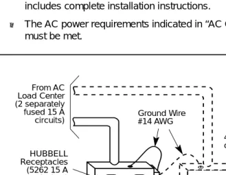
Figure 2-1. AC Grounding Requirements
Ground Bar Mounted on a 4" Box (Square "D" PK9GTA or approved equivalent) From AC
Load Center (2 separately fused 15 A
circuits) Ground Wire#14 AWG
4" Box (RACO 230 or equivalent) HUBBELL
Receptacles (5262 15 A or equivalent)
4" Cover (RACO 807 or equivalent)
Approved Building Ground
#12 or #14 AWG Copper Wire to Each Power Supply Grounding Screw
Single-Point Ground
Installing the Control Unit
Page 2-8 AC Power and Grounding
!
CAUTION:
The AC outlet for the control unit cannot be switch-controlled. Plugging the control unit into such an outlet invites accidental disconnection of the system. The AC outlet must be properly wired as described in “AC Outlet Tests.”
AC Outlet Tests
If the AC outlet tests indicate that any of the power requirements in Table 2-2 are not met, your customer must contact a licensed electrician. Do not install the system until all requirements are met.
If the AC outlet tests reveal any of the following conditions, they must be corrected before you install the system:
■ Open ground
■ Hot and neutral reversed
■ Open hot
Table 2-2. AC Power Requirements
Parameter Value
Nominal voltage 117 V AC
Voltage range 110–125 V AC
Frequency 60 Hz +/– 5%
Maximum current 3 amps per power supply
MERLIN LEGEND Communications System Release 5.0
Installation 555-650-140 June 1997Issue 1
Installing the Control Unit
Page 2-9 AC Power and Grounding
■ Open neutral
■ Hot and ground reversed
!
WARNING:
!
Hazardous voltages are present during the following tests. Follow all instructions carefully when working with AC power line
voltages.
Using an Ideal 61-035 Circuit Tester (or Equivalent)
Plug the circuit tester into the outlet that you want to test.
If the circuit is properly grounded, the yellow and white lights on the tester turn on.
Unplug the circuit tester.