61200305L2-1B
ATLAS 550
System Manual
Trademarks ATLAS 550 System Manual
Trademarks
Any brand names and product names included in this manual are trademarks, registered trademarks, or trade names of their respective holders.
To the Holder of the Manual
The contents of this manual are current as of the date of publication. ADTRAN reserves the right to change the contents without prior notice.
In no event will ADTRAN be liable for any special, incidental, or consequential damages or for commercial losses even if ADTRAN has been advised thereof as a result of issue of this publication.
About this Manual
This manual provides a complete description of the ATLAS 550 System and system software. The purpose of this manual is to provide the technician, system administrator, and manager with general and specific information related to the planning, installation, operation, and maintenance of the ATLAS 550. This manual is arranged so that needed information can be quickly and easily found.
901 Explorer Boulevard P.O. Box 140000 Huntsville, AL 35814-4000
Phone: (256) 963-8000
ATLAS 550 System Manual Revision History
Revision History
Conventions
DocumentRevision Date Description of Changes
A June 2003 Initial release of document. Previous version information found under document 61200305L1-1F. New version created to include updated form factor and hardware information.
B August 2004 Revised to include more detailed mounting information and update compliance requirements.
Notes provide additional useful information.
Cautions signify information that could prevent service interruption.
Safety Instructions ATLAS 550 System Manual
Safety Instructions
When using your telephone equipment, please follow these basic safety precautions to reduce the risk of fire, electrical shock, or personal injury:
1. Do not use this product near water, such as a bathtub, wash bowl, kitchen sink, or laundry tub; in a wet basement; or near a swimming pool.
2. Avoid using a telephone (other than a cordless-type) during an electrical storm. There is a remote risk of shock from lightning.
3. Do not use the telephone to report a gas leak in the vicinity of the leak.
4. Use only the power cord, power supply, and/or batteries indicated in the manual.
5. Do not dispose of batteries in a fire. They may explode. Check with local codes for special disposal instructions.
ATLAS 550 System Manual Compliance Information
Compliance Information
FCC regulations require that the following information be provided to the customer:
1. This equipment complies with Part 68 of the FCC rules and requirements adopted by ACTA. On the equipment housing is a label showing the FCC registration number and ringer equivalence number (REN). If requested, provide this information to the telephone company.
2. If this equipment causes harm to the telephone network, the telephone company may temporarily discontinue your service. If possible, advance notification is given; otherwise, notification is given as soon as possible. The telephone company will advise the customer of the right to file a
complaint with the FCC.
3. The telephone company may make changes in its facilities, equipment, operations, or procedures that could affect the proper operation of this equipment. Advance notification and the opportunity to maintain uninterrupted service are given.
4. If experiencing trouble with this equipment, please contact ADTRAN for repair and warranty information. The telephone company may require this equipment to be disconnected from the network until the problem is been corrected or it is certain the equipment is not malfunctioning. 5. This unit contains no user-serviceable parts.
6. An FCC compliant telephone cord with a modular plug is provided with this equipment. This equipment is designed to be connected to the telephone network or premises wiring using an FCC compatible modular jack, which is complaint with Part 68 and requirements adopted by ACTA. 7. The following information may be required when applying to your local telephone company for
leased line facilities.
8. The REN is used to determine the quantity of devices which may be connected to the telephone line and still have all of those devices ring when the number is called. Excessive RENs on the telephone line may result in the devices not ringing in response to an incoming call. In most, but not all areas, the sum of RENs should not exceed five (5.0). To be certain of the number of devices that may be connected to a line, as determined by the total RENs, contact the local telephone company.
9. This equipment may not be used on coin service provided by the telephone company. Connection to party lines is subject to state tariffs. Contact your state public utility commission or corporation commission for information.
Part # FCC Reg. Number Service Type REN/SOC FIC USOC
1200307L1 HDCUSA-34602-DE-N
1.544 Mbps - SF 1.544 Mbps - SF and B8ZS
1.544 Mbps - ESF 1.544 Mbps - ESF and B8ZS
6.0 N
04DU9-BN
RJ-48C
1200307L2 US:HDCDENAN1200307L2 04DU9-BN
1200314L1 HDCUSA-34601-DE-N 04DU9-BN
1200314L2 US:HDCDENAN1200314L2 04DU9-DN
1200346L1 US:HDCDENAN1200346L1 04DU9-1KN
1200346L2 US:HDCDENAN1200346L2 04DU9-1KN
1200755L1 HDCUSA-34601-DE-N 04DU9-1SN
1200755L2 US:HDCDENAN1200755L2 04DU9-1SN
FCC Radio Frequency Interference Statement ATLAS 550 System Manual
FCC Radio Frequency Interference Statement
This equipment has been tested and found to comply with the limits for a Class A digital device, pursuant to Part 15 of the FCC Rules. These limits are designed to provide reasonable protection against harmful interference when the equipment is operated in a commercial environment. This equipment generates, uses, and can radiate radio frequency energy and, if not installed and used in accordance with the
instruction manual, may cause harmful interference to radio frequencies. Operation of this equipment in a residential area is likely to cause harmful interference in which case the user will be required to correct the interference at his own expense.
Shielded cables must be used with this unit to ensure compliance with Class A FCC limits.
ATLAS 550 System Manual Industry Canada Compliance Information
Industry Canada Compliance Information
Notice: The Industry Canada label applied to the product (identified by the Industry Canada logo or the “IC:” in front of the certification/registration number) signifies that the Industry Canada technical specifications were met.
Notice: The Ringer Equivalence Number (REN) for this terminal equipment is supplied in the
documentation or on the product labeling/markings. The REN assigned to each terminal device indicates the maximum number of terminals that can be connected to a telephone interface. The termination on an interface may consist of any combination of devices subject only to the requirement that the sum of the RENs of all the devices should not exceed five (5).
Canadian Emissions Requirements
This digital apparatus does not exceed the Class A limits for radio noise emissions from digital apparatus as set out in the interference-causing equipment standard entitled “Digital Apparatus,” ICES-003 of the Department of Communications.
Affidavit Requirements for Connection to Digital Services ATLAS 550 System Manual
Affidavit Requirements for Connection to Digital Services
• An affidavit is required to be given to the telephone company whenever digital terminal equipment without encoded analog content and billing protection is used to transmit digital signals containing encoded analog content which are intended for eventual conversion into voiceband analog signal and transmitted on the network.
• The affidavit shall affirm that either no encoded analog content or billing information is being transmitted or that the output of the device meets Part 68 encoded analog content or billing protection specifications.
• End user/customer will be responsible to file an affidavit with the local exchange carrier when connecting unprotected CPE to a 1.544 Mbps or subrate digital service.
ATLAS 550 System Manual Affidavit for Connection Of Customer Premises Equipment
Affidavit for Connection Of Customer Premises Equipment
to 1.544 Mbps And/or Subrate Digital Services
For the work to be performed in the certified territory of ___________________(telco name)
State of ________________
County of ________________
I, _______________________ (name), _____________________________(business address),
____________________ (telephone number) being duly sworn, state:
I have responsibility for the operation and maintenance of the terminal equipment to be connected to 1.544 Mbps and/or ________ subrate digital services. The terminal equipment to be connected complies with Part 68 of the FCC rules except for the encoded analog content and billing protection specifications. With respect to encoded analog content and billing protection:
( ) I attest that all operations associated with the establishment, maintenance, and adjustment of the digital CPE with respect to analog content and encoded billing protection information continuously complies with Part 68 of the FCC Rules and Regulations.
( ) The digital CPE does not transmit digital signals containing encoded analog content or billing information which is intended to be decoded within the telecommunications network.
( ) The encoded analog content and billing protection is factory set and is not under the control of the customer.
I attest that the operator(s)/maintainer(s) of the digital CPE responsible for the establishment, maintenance, and adjustment of the encoded analog content and billing information has (have) been trained to perform these functions by successfully having completed one of the following (check appropriate blocks):
( ) A. A training course provided by the manufacturer/grantee of the equipment used to encode analog signals; or
( ) B. A training course provided by the customer or authorized representative, using training materials and instructions provided by the manufacturer/grantee of the equipment used to encode analog signals; or
( ) C. An independent training course (e.g., trade school or technical institution) recognized by the manufacturer/grantee of the equipment used to encode analog signals; or
Affidavit for Connection Of Customer Premises Equipment ATLAS 550 System Manual
I agree to provide ______________________ (telco’s name) with proper documentation to demonstrate compliance with the information as provided in the preceding paragraph, if so requested.
_________________________________Signature
_________________________________Title
_________________________________ Date
Transcribed and sworn to before me
This ________ day of _______________, _______
_________________________________ Notary Public
My commission expires:
ATLAS 550 System Manual Warranty and Customer Service
Warranty and Customer Service
ADTRAN will replace or repair this product within the warranty period if it does not meet its published specifications or fails while in service. Warranty information can be found at: http://support.adtran.com
(Click on Warranty and Repair Information, under Support.)
Product Registration
Registering your product helps ensure complete customer satisfaction. Please take time to register your products on line at http://support.adtran.com. Click on Product Registration under Support.
Customer Service, Product Support Information, and Training
A return material authorization (RMA) is required prior to returning equipment to ADTRAN. For service, RMA requests, training, or more information, use the following contact information:.
Repair and Return
If you determine that a repair is needed, please contact our Customer and Product Service (CaPS) department to have an RMA number issued. CaPS should also be contacted to obtain information regarding equipment currently in house or possible fees associated with repair.
Identify the RMA number clearly on the package (below address), and return to the following address:
CaPS Department (256) 963-8722
ADTRAN Customer and Product Service 901 Explorer Blvd. (East Tower)
Customer Service, Product Support Information, and Training ATLAS 550 System Manual
Pre-Sales Inquiries and Applications Support
Your reseller should serve as the first point of contact for support. If additional pre-sales support is needed, the ADTRAN Support web site provides a variety of support services such as a searchable knowledge base, latest product documentation, application briefs, case studies, and a link to submit a question to an Applications Engineer. All of this, and more, is available at:
When needed, further pre-sales assistance is available by calling our Applications Engineering Department.
Post-Sale Support
Your reseller should serve as the first point of contact for support. If additional support is needed, the ADTRAN Support web site provides a variety of support services such as a searchable knowledge base, updated firmware releases, latest product documentation, service request ticket generation and
trouble-shooting tools. All of this, and more, is available at:
When needed, further post-sales assistance is available by calling our Technical Support Center. Please have your unit serial number available when you call.
Installation and Maintenance Support
The ADTRAN Custom Extended Services (ACES) program offers multiple types and levels of installation and maintenance services which allow you to choose the kind of assistance you need. This support is available at:
For questions, call the ACES Help Desk.
http://support.adtran.com
Applications Engineering (800) 615-1176
http://support.adtran.com
Technical Support (888) 4ADTRAN
http://www.adtran.com/aces
ATLAS 550 System Manual Customer Service, Product Support Information, and Training
Training
The Enterprise Network (EN) Technical Training Department offers training on our most popular products. These courses include overviews on product features and functions while covering applications of
ADTRAN's product lines. ADTRAN provides a variety of training options, including customized training and courses taught at our facilities or at your site. For more information about training, please contact your Territory Manager or the Enterprise Training Coordinator.
Training Phone (800) 615-1176, ext. 7500 Training Fax (256) 963-6700
Table of Contents
Section 1
System Description . . . 17
Provides an overview of the ATLAS 550 System.
Section 2
Engineering Guidelines . . . 25
Provides equipment dimensions, power requirements, front panel design, back panel design, LEDs, and at-a-glance specifications.
Section 3
Network Turnup Procedure . . . 51
Provides shipment contents list, grounding instructions, mounting options, and specifics of sup-plying power to the unit.
Section 4
User Interface Guide . . . 63
Provides detailed descriptions of all menu options and configuration parameters available for the ATLAS 550.
Section 5
Detail Level Procedures. . . 309
DLP-1 Connecting a VT100 Terminal or PC to the ADMIN or CRAFT Port. . . 311
DLP-2 Logging in to the ATLAS 550 . . . 313
DLP-3 Setting IP Parameters for the ATLAS 550 . . . 315
DLP-4 Verifying Communications Over an IP LAN . . . 317
DLP-5 Adding and Removing Users and Changing Password Security Levels . . . 321
DLP-6 Updating the Firmware Using TFTP . . . 323
DLP-7 Updating the Firmware Using XMODEM . . . 327
DLP-8 Saving the Current Configuration Using TFTP . . . 331
DLP-9 Loading a Configuration Using TFTP . . . 333
DLP-10 Saving and Transferring a Current Configuration Using XMODEM . . . 335
DLP-11 Loading a Configuration Using XMODEM . . . 337
DLP-12 Connecting the ATLAS 550 to an External Modem . . . 339
DLP-13 Using the ADTRAN Utility Syslog (Event Log) . . . 341
DLP-14 Connecting the Alarm Contacts . . . 345
DLP-15 Using the Alarm Connections and the ACO Button. . . 349
Section 6
Configuration Guides. . . 351
CFG-1 Dial Backup for Dedicated T1 Circuits . . . 353
Section 7
System Event Logging. . . 365
Explains the System Event Logging messages for the ATLAS 550 and provides instructions for configuring the Event Log.
Section 8
ADTRAN Utilities . . . 379
Provides instructions for configuring and using the ADTRAN Utilities software programs in-cluding Telnet, VT100, Syslog, and TFTP.
Section 9
MIBs. . . 389
SYSTEM DESCRIPTION
Provides an overview of the ATLAS 550 System.
C
ONTENTSSystem Overview. . . 16
Features and Benefits . . . 16
Configuration and Management . . . 16
Software Upgradeable . . . 16
Signaling Support . . . 16
ISDN Switch Types . . . 16
Dedicated Connection Maps . . . 17
Switched Connection Maps. . . 17
Testing . . . 17
Performance Monitoring . . . 17
Frame Relay . . . 17
PPP Switching. . . 17
Option Modules . . . 18
T1/PRI Network Interface Module (P/N 1200307L1/L2) . . . 18
E1/PRA Network Interface Module (P/N 1200308L1) . . . 18
Modem Management Network Module (P/N 1200341L1). . . 19
BRI DBU Network Interface Module (P/N 1200327L1) . . . 19
Dual Nx 56/64 Option Module (P/N 1200311L1). . . 19
Dual USSI Option Module (P/N 1200754L1). . . 19
Dual/Quad T1/PRI Option Module (P/N 1200314L1/L2 and 1200755L1/L2) . . . 19
Quad Basic Rate ISDN (U-Interface) Option Module (P/N1200315L1) . . . 19
Quad Basic Rate ISDN (S/T-Interface) Option Module (P/N 1200764L1) . . . 19
Octal/Quad FXS Option Module (P/N 1200309L1/1200328L1) . . . 19
Octal/Quad FXO Option Module (P/N 1200310L1/1200329L1) . . . 20
Octal E&M Option Module (P/N 1200313L1) . . . 20
Legacy Data Option Module (P/N 1200342L1) . . . 20
NxT1 HSSI/V.35 Option Module (P/N 1200346L2) . . . 20
Octal Ethernet Switch Option Module (P/N 1200766L1). . . 20
Resource Host Module (P/N 1200324L1) . . . 20
4, 8, 16, 24 Channel Voice Compression Resource Modules (P/N 1200312Lx) . . . 20
32 Channel ADPCM Resource Module (P/N 1200752L1) . . . 20
Section 1 System Description ATLAS 550 System Manual
1.
SYSTEM OVERVIEW
The ATLAS 550 is a modular, highly scalable platform that provides robust solutions for the wide-area communication needs of small-to-medium corporations and network access providers. The ATLAS 550 is an Integrated Access System with extensive support of dedicated bandwidth management and access switching. It contains a high-performance CPU and powerful communications drivers which support applications such as frame relay, dial-backup, and PPP (point-to-point protocol).
The ATLAS 550 architecture also includes a packet and circuit switching bussing scheme. The result is a system capable of supporting bandwidth requirements of up to nine T1 circuits or five Primary Rate ISDN (PRI) circuits. Designed for standalone, rackmount, or wallmount installations, the ATLAS 550 base unit provides two hot-swappable network interfaces and four expansion slots that accommodate hot-swappable option modules for a variety of applications. A 10/100BaseT Ethernet connection for IP routing and network management is standard with the ATLAS 550 base unit.
With the ATLAS 550, you can consolidate voice, data, and video applications into a single platform while optimizing wide area bandwidth and reducing equipment costs. The ATLAS 550 architecture and the four expansion slots accept a variety of modules, making it one of the most versatile access systems on the market.
2.
FEATURES AND BENEFITS
The following is a brief list of ATLAS 550 features and benefits:
Configuration and Management
• VT100 emulation
• SNMP, per MIB II (RFC1213), DS1/E1 MIB (RFC1406), Frame Relay MIB (RFC1315), and ADTRAN private MIBs
• Telnet
• Dial-up remote management via optional Modem Management Network Module (P/N 1200341L1) • Six levels of password protection and privileges
Software Upgradeable
• Flash memory • TFTP download
• XMODEM via CRAFT or ADMIN ports
Signaling Support
• ISDN D Channel
• Robbed bit, E&M, Ground Start, Loop Start
ATLAS 550 System Manual Section 1 System Description
Dedicated Connection Maps
• Up to five connection maps
• Time of day and day of week configurable • Preserves signaling through cross-connect • No effect on nonconfigured channels
Switched Connection Maps
• Inbound and outbound call filtering and blocking
Testing
• Local and remote: payload/line, V.54 (depending on installed modules) • Patterns: 511, QRSS, all ones, all zeros (depending on installed modules)
Performance Monitoring
• Reports: Information stored for last 24 hours in 15-minute increments • Performance statistics per TR54016, T1.403, RFC1406
• Alarm reporting per TR54016, T1.403
Frame Relay
• Routes Internet Protocol (IP) traffic between the Ethernet port and a public frame relay network, a private frame relay network, or a point-to-point network
• Concentrates IP traffic from a public or private frame relay network and passes frame relay data with RFC 1490 encapsulation to one or more serial ports (V.35)
• Passes Systems Network Architecture (SNA), Bisync, and other legacy protocols between a public or private frame relay network and an external DTE running Frame Relay to the ATLAS 550
• Performs voice compression/decompression (G.723.1) and interfaces to either a Private Branch Exchange (PBX) or the Public Switched Telephone Network (PSTN) (requires an additional option module, the VCOM Module—P/N 1200312Lx)
• Performs voice packetization (G.711 or Transparent) or voice compression/decompression (G.726) and interfaces to either a PBX or the PSTN (requires an additional option module, the 32-Channel ADPCM Resource Module—P/N 1200752L1)
• Supports LMI, Annex D, or Annex A signaling on frame relay connections
PPP Switching
• Supports up to 100 simultaneous PPP connections
• Performs PAP, CHAP, or EAP authentication methods on a per-connection basis • Includes keepalive functionality for PPP connections
Section 1 System Description ATLAS 550 System Manual
3.
OPTION MODULES
Each of the following ATLAS 550 option modules is hot-swappable:
• T1/PRI Network Interface Module (P/N 1200307L1/L2) • E1/PRA Network Interface Module (P/N 1200308L1) • Modem Management Network Module (P/N 1200341L1) • BRI DBU Network Interface Module (P/N 1200327L1) • Dual Nx 56/64 Option Module (P/N 1200311L1) • Dual USSI Option Module (P/N 1200754L1)
• Dual/Quad T1/PRI Option Module (P/N 1200314L1/L2 and 1200755L1/L2) • Quad Basic Rate ISDN (U-Interface) Option Module (P/N1200315L1) • Quad Basic Rate ISDN (S/T-Interface) Option Module (P/N1200764L1) • Octal/Quad FXS Option Module (P/N 1200309L1/1200328L1)
• Octal/Quad FXO Option Module (P/N 1200310L1/1200329L1) • Octal E&M Option Module (P/N 1200313L1)
• Octal Ethernet Switch Option Module (P/N 1200766L1) • Resource Host Module (P/N 1200324L1)
• 4, 8, 16, 24 Channel Voice Compression Resource Modules (P/N 1200312Lx) • 32 Channel ADPCM Resource Module (P/N 1200752L1)
• Nx 56/64 BONDing Resource Module (P/N 1200326L1) • Legacy Data Option Module (P/N 1200342L1)
• NxT1 HSSI/V.35 Option Module (P/N 1200346L2)
Each option module contains a variety of performance and alarm status information. Although default values reflect the most common configurations, several features of each module are user-configurable. All option modules contain an extensive self-test as well as tests designed for the technology they incorporate.
T1/PRI Network Interface Module (P/N 1200307L1/L2)
The T1/PRI Network Interface Module provides one channelized T1 or PRI interface. This interface operates in DS-1 or DSX-1 mode and can deliver timing for the system. The ATLAS 550 domestic system (P/N 1200305L2) ships with one installed T1/PRI Network Interface Module.
E1/PRA Network Interface Module (P/N 1200308L1)
The E1/PRA Network Interface Module provides one channelized E1 or PRA interface using either a standard DB-15 or BNC connector. This interface operates in CCS or CAS signaling mode and can deliver timing for the system. The ATLAS 550 international system (P/N 1200306L2) ships with one installed
ATLAS 550 System Manual Section 1 System Description
Modem Management Network Module (P/N 1200341L1)
The Modem Management Network Module provides a single analog interface (RJ-11) for dial-up remote management of the ATLAS 550 System. The internal modem supports connection rates from 2400 bps to 33.6 kbps and performs standard data modulation, error correction, and data compression.
BRI DBU Network Interface Module (P/N 1200327L1)
The BRI DBU Network Interface Module provides a single Basic Rate ISDN (BRI) U interface capable of operating in either NT or LT mode and delivering timing for the system. The BRI DBU Network Interface Module supports two independent calls or one BONDed call. All BONDing functionality is provided on the module, so the BONDing resource module (1200326L1) is not required.
Dual Nx 56/64 Option Module (P/N 1200311L1)
The Dual Nx 56/64 Module provides two synchronous V.35 DTE ports that can operate from 56 kbps to 2.048 Mbps in steps of 56 or 64 kbps. Either port can deliver timing for the system.
Dual USSI Option Module (P/N 1200754L1)
The Dual USSI Option Module provides two synchronous DTE ports that can operate from 56 kbps to 2.048 Mbps in steps of 56 or 64 kbps. Either port can deliver timing for the system. Using the appropriate adapter cables, the Dual USSI Option Module can provide the following interface types: EIA-530, EIA-530A, RS-449, RS-232, and CCITT X.21.
Dual/Quad T1/PRI Option Module (P/N 1200314L1/L2 and 1200755L1/L2)
The Dual/Quad T1/PRI Module provides two or four channelized T1 or PRI interfaces. Each interface can operate independently in DS-1 or DSX-1 mode, and any port can deliver timing for the system.
Quad Basic Rate ISDN (U-Interface) Option Module (P/N1200315L1)
The Quad Basic Rate ISDN (U) Module provides four BRI U interfaces, each capable of operating in either NT or LT mode. When operating in NT mode, any port can deliver timing for the system.
Quad Basic Rate ISDN (S/T-Interface) Option Module (P/N 1200764L1)
The Quad Basic Rate ISDN (S/T) Module provides four BRI S/T interfaces, each capable of operating in LT mode.
Octal/Quad FXS Option Module (P/N 1200309L1/1200328L1)
Section 1 System Description ATLAS 550 System Manual
Octal/Quad FXO Option Module (P/N 1200310L1/1200329L1)
The Octal/Quad FXO Option Modules provide eight or four analog voice-grade interfaces. Each interface supports loop-start and ground-start operation. Applications include termination of analog PSTN trunks and connections to PBX station-side interfaces (Off Premise Extension – OPX).
Octal E&M Option Module (P/N 1200313L1)
The Octal E&M Option Module provides eight analog voice-grade interfaces (2-wire or 4-wire) for use as tie-trunks (using E&M signaling) or dedicated transmission only (TO) interfaces (for additional data services). The module supports E&M signaling types 1-5.
Legacy Data Option Module (P/N 1200342L1)
The Legacy Data Option Module provides four EIA-232 or V.35 interfaces (or any combination up to four) for synchronous or asynchronous packet data applications. Protocols supported include SNA/SDLC, Frame Relay, PPP, Transparent Bit-oriented (TBOP), and Transparent Async. The Legacy Data Option Module includes an adapter cable to provide four EIA-232 (DB-25) interfaces. (An optional V.35 adapter cable (P/N 1200348L1) is also available.)
NxT1 HSSI/V.35 Option Module (P/N 1200346L2)
The NxT1 HSSI/V.35 Option Module aggregates bandwidth of up to eight T1s (four T1s from the built-in module interfaces and four from other installed T1 interfaces) into a single logical channel on the HSSI interface or the V.35 interface (using an optional adapter cable). The NxT1 HSSI/V.35 Option Module supports point-to-point T1 applications only. Any of the four built-in T1 ports of the NxT1 HSSI/V.35 Option Module can provide timing for the ATLAS 550 system.
Octal Ethernet Switch Option Module (P/N 1200766L1)
The Octal Ethernet Switch Option Module provides eight interfaces that can operate as 10BaseT or 100BaseTX. Each interface uses auto-negotiation to support Ethernet traffic at 10 Mbps or 100 Mbps, half-duplex or full-duplex. Automatic MDI/MDIX crossover is provided to simplify LAN connections.
Resource Host Module (P/N 1200324L1)
The Resource Host Module provides an inexpensive way to use a desired plug-on resource module, such as the Voice Compression Module. This module has no other functionality except to act as the base for the plug-on resource modules.
4, 8, 16, 24 Channel Voice Compression Resource Modules (P/N 1200312Lx)
The Voice Compression Module (VCOM Module) combines with other ATLAS 550 components to implement Voice over Frame Relay (VoFR). The Voice Compression Resource Modules support 4, 8, 16, or 24 simultaneous compressed calls using G.723.1 or Netcoder compression algorithms.
32 Channel ADPCM Resource Module (P/N 1200752L1)
ATLAS 550 System Manual Section 1 System Description
Nx 56/64 BONDing Resource Module (P/N 1200326L1)
The Nx 56/64 BONDing Resource Option Module supports multiple, independent BONDing sessions with each session capable of using from two to thirty-two channels of 56K or 64K data. The Nx 56/64
ENGINEERING GUIDELINES
Provides equipment dimensions, power requirements, front panel design, back panel design, LEDs, and at-a-glance specifications.
C
ONTENTSEquipment Dimensions. . . 25 Power Requirements . . . 25 Reviewing the Front Panel Design . . . 25 ACO Switch. . . 25 CRAFT Port (DB-9, female) . . . 25 Front Panel LEDs . . . 26 Reviewing the Back Panel Design . . . 29 AC System . . . 29 DC System . . . 29 ADMIN Port (USOC RJ-48C) . . . 30 Ethernet Connection (USOC RJ-48C) . . . 30 External Alarm Relay Monitor Connection . . . 31 Alarm Relay Connection . . . 31 Network Interface Modules . . . 31 T1/PRI Network Interface Module (P/N 1200307L1/L2), USOC RJ-48C . . . 32 E1/PRA Network Interface Module (P/N 1200308L1), 15-pin female D-connector. . . 32 Modem Management Network Module (P/N 1200341L1), USOC RJ-11C . . . 33 BRI DBU Network Module (P/N 1200327L1), USOC RJ-49C. . . 34 Option Module Interfaces . . . 34 Octal/Quad FXS Option Module (P/N 1200309L1/1200328L1), 8-Pin Modular Jack . . . 34 Octal/Quad FXO Option Module (P/N 1200310L1/1200329L1), 8-Pin Modular Jack . . . 35 Dual Nx 56/64 Option Module (P/N 1200311L1), V.35 Winchester . . . 35 Dual USSI Option Module (P/N 1200754L1), DB-78 . . . 36 Octal E&M Option Module (P/N 1200313L1), 8-Pin Modular Jack . . . 40 Dual/Quad T1/PRI Option Module (P/N 1200314L1/L2 and 1200755L1/L2), USOC RJ-48C . . 41 Quad BRI (U-Interface) Option Module (P/N 1200315L1), USOC RJ-48C. . . 41 Quad BRI ISDN (S/T Interface) Option Module (P/N 1200764L1), USOC RJ-45 . . . 41 NxT1 HSSI Option Module (P/N 1200346L1), 50-Pin SCSI-II . . . 42 NxT1 HSSI/V.35 Option Module (P/N 1200346L2) . . . 42 Legacy Data Option Module (P/N 1200342L1), EIA-232 and V.35. . . 44 Octal Ethernet Switch Option Module (P/N 1200766L1), USOC RJ-48C . . . 45 At-A-Glance Specifications . . . 46
F
IGURESSection 2 Engineering Guidelines ATLAS 550 System Manual
T
ABLESATLAS 550 System Manual Section 2 Engineering Guidelines
1.
EQUIPMENT DIMENSIONS
The ATLAS 550 base unit dimensions are 17.08” W x 11.67” D x 3.47” H. The option modules fit inside the base unit.
2.
POWER REQUIREMENTS
The ATLAS 550 has a maximum power consumption of 60 W and a maximum current draw of 2 A (AC System) or 5 A (DC System) regardless of the configuration of option modules installed in the base unit.
3.
REVIEWING THE FRONT PANEL DESIGN
The front panel contains the Alarm Cut-off switch (ACO), the CRAFT port, and the status LEDs for the system controller, the network modules, and the option modules. Figure 1 identifies the ACO switch, the
CRAFT port, and theLEDs.
Figure 1. ATLAS 550 Front Panel Layout
ACO Switch
Pressing the ACO switch deactivates (clears) the Alarm Relay, located on the back panel of the
ATLAS 550, after an alarm condition has occurred. If an alarm condition is corrected and then reoccurs, the Alarm Relay re-energizes.
CRAFT Port (DB-9, female)
Use the CRAFT port to configure the system via an EIA-232 connection. Table 1 on page 28 gives the
CRAFT port pinout.
Network
Module LEDs Option Module LEDs Craft
Section 2 Engineering Guidelines ATLAS 550 System Manual
Front Panel LEDs
With the ATLAS 550 powered-up, the front panel LEDs provide visual information about the status of the ATLAS 550 and any option modules that may be installed. Table 2 provides a brief description of the front panel features, and Table 3 on page 29 provides detailed information about the LEDs.
Table 1. CRAFT Port Pinout
Pin Name Description
1, 4, 6-9 —– Unused
2 RD Receive Data (output)
3 TD Transmit Data (input)
5 SG Signal Ground
Table 2. ATLAS 550 Front Panel Description
Feature Description
System Status LEDs Display the general status of the entire ATLAS 550 (see Table 3 on page 29). Power Indicates the unit is on or off.
System Indicates the status of the system controller and other system conditions. Ethernet Indicates the status of the Ethernet port.
Remote Indicates whether a user is logged into the unit.
Network Module LEDs Display the status of the two network interfaces (see Table 3 on page 29). All LEDs are off if no network module is installed.
OK Indicates that the network interface is operating correctly. Test Indicates that the network interface is in test mode. Error Blinks to indicate the occurrence of error events. Alarm Indicates an alarm condition on the network interface.
Option Module LEDs Display (by row) the operational condition of each module installed in the option slots (see Table 3 on page 29). All LEDs will be off if no option module is installed.
Status Indicates the operational condition of each of the modules installed in the four option slots.
Online Indicates whether the module is available for use or is currently in use. If the module is manually taken offline, this LED is turned off.
Test Indicates that one or more module ports are in test.
ATLAS 550 System Manual Section 2 Engineering Guidelines
Table 3. Description of ATLAS 550 LEDs For these LEDs... This color light... Indicates that...
System Status
Power Green the unit is on.
Off the unit is off.
System
Green (solid) no diagnosed system faults were found. Green (fast blink) a flash download is in progress.
Yellow (solid) a fault was diagnosed, but the condition no longer exists. The condition will be recorded in the system log.
Red (solid) an error condition with either the power supply or the system temperature is present. Red (fast blink) a fatal error occurred during flash download.
Off power is not currently supplied to the system.
Ethernet
Green (solid) the physical link is up. Green (flashing) there is activity on the LAN.
Off the physical link is down - no Ethernet connection.
Remote Yellow
a user is logged into the system via the ADMIN/CRAFT port or via the ETHERNET port.
Off there are no users logged into the system. Network Modules Status
OK Green (solid)
the network interface is operating normally with error-free operation. If the interface experiences alarms, the OK LED remains off.
Test Yellow (solid)
the interface is operating in a test mode. This includes a self-test, a test pattern, or a test loopback. When
illuminated, this LED also indicates that normal data flow is not occurring on the module ports.
Error Red (blink) an error such as BPV (bipolar violation), OOF (out of frame), or CRC (cyclic redundancy check) has occurred.
Alarm Red (solid)
Section 2 Engineering Guidelines ATLAS 550 System Manual
Option Modules Status
Status Green (solid) one or both modules (in the case of a Resource Module) are OK.
Green (fast blink)
one or both modules (in the case of a Resource Module) have been set offline by the user,
OR
one or both modules (in the case of a Resource Module) have invalid flash memory.
Red (solid) a port on the installed module is currently in alarm. Red (fast blink) one module has no response, has been removed, or is not supported. Red (slow blink) one module is not ready.
Off no module occupies the slot.
Online Green (solid) one or both modules (in the case of a Resource Module) have an active connection.
Green (fast blink) one module has invalid flash memory or is downloading firmware. Green (slow blink) one module has an active connection.
Test Yellow (solid) one module is in a test mode. Table 3. Description of ATLAS 550 LEDs (Continued)
ATLAS 550 System Manual Section 2 Engineering Guidelines
4.
REVIEWING THE BACK PANEL DESIGN
AC System
The ATLAS 550 (AC System) back panel contains four slots for housing option modules which provide a variety of additional resources and data ports. All slots are functionally identical. The ATLAS 550 also contains two slots for housing network modules (see Figure 2).
Figure 2. ATLAS 550 (AC System) Back Panel
DC System
The ATLAS 550 (DC System) back panel contains four slots for housing option modules which provide a variety of additional resources and data ports. All slots are functionally identical. The ATLAS 550 also contains two slots for housing network modules (see Figure 3).
O I
ALL EMPTY SLOTS MUST BE
COVERED WITH BLANK PANELS
500 Series
500 Series
500 Series
CAUTION: FOR CONTINUED PROTECTION
AGAINST RISK OF FIRE, REPLACE ONLY
WITH SAME TYPE AND RATING OF FUSE.
ETHERNET ADMIN
RELAY ALARM
MON NCNOCOM
500 Series
NETWORK 2 NETWORK 1
500 Series 500 Series
FUSE RATING: 2A/250V SLO-BLO 90-240VAC, 2A 50/60Hz
1 2 3 4 AC Power Connection Option Module Slots Alarm Relay Connection
Network Module Slots 10/100BaseT
Ethernet ADMIN Port Power Switch External Alarm Relay Connection O I
ALL EMPTY SLOTS MUST BE
COVERED WITH BLANK PANELS
500 Series
500 Series
500 Series
CAUTION: FOR CONTINUED PROTECTION
AGAINST RISK OF FIRE, REPLACE ONLY
WITH SAME TYPE AND RATING OF FUSE.
ETHERNET ADMIN
RELAY ALARM
MON NCNOCOM
500 Series NETWORK 2 NETWORK 1 500 Series 500 Series + Ð
USE COPPER CONDUCTORS ONLY
INPUT: 24Ð48V ,4A
FUSE: 5A/48VDC 1 2 3 4 DC Power Connection Option Module Slots Alarm Relay Connection
Network Module Slots ADMIN
Section 2 Engineering Guidelines ATLAS 550 System Manual
ADMIN Port (USOC RJ-48C)
The ADMIN port (EIA-232) connects to a computer or modem (see Table 4 for the pinout) and provides the following functions:
• Accepts EIA-232 input from a PC or a modem for controlling the ATLAS 550. • Operates at 2400, 9600, 19200, or 38400 bps.
• Acts as input for either VT100 or PC control.
• Acts as an interface for flash memory software downloads using XMODEM.
Ethernet Connection (USOC RJ-48C)
The ETHERNET port (RJ-48C) provides a 10/100BaseT ETHERNET LAN connection, which is used for IP routing, TFTP, SNMP, and Telnet connections. Table 5 shows the pinout.
Table 4. ADMIN Port Pinout
Pin Name Description
1 SG Signal Ground
2 RTS Request to Send (output), follows CTS 3 TD Transmit Data (input)
4 DTR Data Terminal Ready (output), +12 V 5 RD Receive Data (output)
6 DCD Data Carrier Detect (input)
7 —– Not Connected
8 CTS Clear to Send (input)
Table 5. Ethernet Pinout
Pin Name Description
1 TX1 Transmit Positive
2 TX2 Transmit Negative
3 RX1 Receive Positive
4, 5 —– Unused
6 RX2 Receive Negative
ATLAS 550 System Manual Section 2 Engineering Guidelines
External Alarm Relay Monitor Connection
This connection alerts the user when a selected external alarm condition exists. This connection could be used to monitor a UPS with dry contacts or another ATLAS 550. The 2-pin, removable terminal block connects with external wiring. Refer to DLP-14, Connecting the Alarm Contacts, for detailed instructions. Clear the alarm condition by pressing the ACO switch located on the front panel of the ATLAS 550. Table 6 shows the pinout for the External Alarm Relay connector.
Alarm Relay Connection
This connection alerts the user when a selected alarm condition exists. The 4-pin, removable terminal block connects with external wiring. Refer to DLP-14, Connecting the Alarm Contacts, for detailed instructions. Clear the alarm condition by pressing the ACO switch located on the front panel of the ATLAS 550. Table 7 shows the pinout for the Alarm Relay connector.
5.
NETWORK INTERFACE MODULES
The ATLAS 550 provides two Network Interface Slots that allow different types of interfaces to be used. Available Network Interface Modules include the following:
• T1/PRI Network Interface Module (P/N 1200307L1/L2), USOC RJ-48C. (See page 34.)
• E1/PRA Network Interface Module (P/N 1200308L1), 15-pin female D-connector. (See page 34.) • Modem Management Network Module (P/N 1200341L1), USOC RJ-11C. (See page 35.)
• BRI DBU Network Module (P/N 1200327L1), USOC RJ-49C. (See page 36.)
Table 6. External Relay Monitor Connector Pinout
Pin Name Description
1 ALARM OUT Outputs EIA-232 level signal for connection to external alarm contacts. 2 ALARM IN Monitors signal coming from external alarm contacts.
Table 7. Alarm Relay Connector Pinout
Pin Name Description
1 NORMALLY CLOSED (NC) Opens when a selected alarm condition is present. 2 NORMALLY OPEN (NO) Closes when a selected alarm condition is present.
Section 2 Engineering Guidelines ATLAS 550 System Manual
T1/PRI Network Interface Module (P/N 1200307L1/L2), USOC RJ-48C
The T1/PRI Network Interface Module provides a single T1/PRI port (see Table 8 for the pinout) and complies with the applicable ANSI and AT&T® standards. The T1/PRI Network Interface Module
provides the following functions:
• AMI or B8ZS coding • Manual line build-out • D4 or ESF framing
• Network performance monitoring and reporting • Test loopbacks with QRSS generation and checking • Extensive self-testing
Test Interface
The MON INand OUT Bantam test jacks provide a bridged access jack for nonintrusive monitoring of the incoming T1. When connected to this jack, configure the test equipment for bridged termination.
E1/PRA Network Interface Module (P/N 1200308L1), 15-pin female D-connector
The E1/PRA Network Interface Module provides a single E1/PRA port (see Table 9 on page 35) that pro-vide the following functions:
• AMI or HDB3 coding • Manual line build-out
• NFAS, FAS, TS16 MF and CRC-4 framing • Supports CCS or CAS signaling
• Network performance monitoring and reporting • Test loopbacks with QRSS generation and checking • Extensive self-testing
Table 8. T1/PRI Network Interface Module RJ-48C Pinout
Pin Name Description
1 RXDATA-RING (R1) Receive data from the network 2 RXDATA-TIP (T1) Receive data from the network
3 ––––– Unused
4 TXDATA-RING (R) Transmit data toward the network 5 TXDATA-TIP (T) Transmit data toward the network
ATLAS 550 System Manual Section 2 Engineering Guidelines
Test Interface
This module contains two test interfaces: NETWORK and MON. The NETWORK IN and OUT Bantam test jacks provide intrusive test capability for the incoming E1. By connecting test equipment to these jacks, the E1 connection breaks and the test equipment terminates the incoming E1. The MON IN and OUT Bantam test jacks provide a bridged access jack for nonintrusive monitoring of the incoming E1. When connected to this jack, configure the test equipment for bridged termination.
Modem Management Network Module (P/N 1200341L1), USOC RJ-11C
The Modem Management Network Module provides a single 6-pin modular jack (RJ-11C) (see Table 10 for the pinout). The Modem Management Network Module provides the following functions:
• V.34, V.32bis, V.32, V.22, V.23, and V.21 data modulation schemes • Connection rates from 2400 to 33.6K baud
• V.42 LAPM, MNP 2-4, and MNP 10 error correction methods • V.42bis and MNP 5 data compression algorithms
Table 9. E1/PRA Network Interface 15-pin Female D-connector Pinout
Pin Name Description
1 TXDATA-RING (R) Transmit data toward the network
2,4,5,7 FRAME GROUND (FG) Grounded to chassis
3 RXDATA-RING (R1) Receive data from the network
6,8,10,12-15 –––––– Unused
9 TXDATA-TIP (T) Transmit data toward the network
11 RXDATA-TIP (T1) Receive data from the network
Table 10. Modem Management Network Module RJ-11C Pinout
Pin Name Description
1, 2, 5, 6 ––– Unused
Section 2 Engineering Guidelines ATLAS 550 System Manual
BRI DBU Network Module (P/N 1200327L1), USOC RJ-49C
The BRI DBU Network Module provides a single 8-pin jack (RJ-49C) for connection to a standard BRI U inter-face circuit. All BONDing functionality for 2B+D operation is provided on the module. Table 11 shows the pinout for this connection.
6.
OPTION MODULE INTERFACES
The ATLAS 550 contains four option slots that hold a variety of modules. This sections provides a brief description of these modules and their pinouts, as follows:
• Octal/Quad FXS Option Module (P/N 1200309L1/1200328L1), 8-Pin Modular Jack. (See page 36.) • Octal/Quad FXO Option Module (P/N 1200310L1/1200329L1), 8-Pin Modular Jack. (See page 37.) • Dual Nx 56/64 Option Module (P/N 1200311L1), V.35 Winchester. (See page 37.)
• Dual USSI Option Module (P/N 1200754L1), DB-78. (See page 38.)
• Octal E&M Option Module (P/N 1200313L1), 8-Pin Modular Jack. (See page 42.)
• Dual/Quad T1/PRI Option Module (P/N 1200314L1/L2 and 1200755L1/L2), USOC RJ-48C. (See page 43.) • Quad BRI (U-Interface) Option Module (P/N 1200315L1), USOC RJ-48C. (See page 43.)
• Quad BRI ISDN (S/T Interface) Option Module (P/N 1200764L1), USOC RJ-45. (See page 43.) • NxT1 HSSI Option Module (P/N 1200346L1), 50-Pin SCSI-II. (See page 44.)
• NxT1 HSSI/V.35 Option Module (P/N 1200346L2). (See page 44.)
• Legacy Data Option Module (P/N 1200342L1), EIA-232 and V.35. (See page 46.) • Octal Ethernet Switch Option Module (P/N 1200766L1), USOC RJ-48C. (See page 47.)
Octal/Quad FXS Option Module (P/N 1200309L1/1200328L1), 8-Pin Modular Jack
Each port of the Octal/Quad FXS Option Module has a single 8-pin modular jack. Table 12 shows the pinout.
Table 11. BRI DBU Network Module RJ-49C Pinout
Pin Name Description
1, 2, 3, 6, 7, 8 –––– Unused
4 RING Ring to and from the network interface
5 TIP Tip to and from the network interface
Table 12. FXS 8-Pin Modular Jack Pinout
Pin Name Description
1, 2, 3, 6, 7, 8 –––– Unused
ATLAS 550 System Manual Section 2 Engineering Guidelines
Octal/Quad FXO Option Module (P/N 1200310L1/1200329L1), 8-Pin Modular Jack
Each port of the Octal/Quad FXO Option Module has a single 8-pin modular jack. Table 13 shows the pinout.
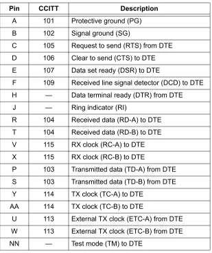
Dual Nx 56/64 Option Module (P/N 1200311L1), V.35 Winchester
Each port of the Dual Nx 56/64 Option Module has a V.35 Winchester-style connection as defined in Table 14.
Table 13. FXO 8-Pin Modular Jack Pinout
Pin Name Description
1, 2, 3, 6, 7, 8 –––– Unused
4 RING Ring to and from the analog phone interface 5 TIP Tip to and from the analog phone interface
Table 14. V.35 Winchester Pinout
Pin CCITT Description
A 101 Protective ground (PG)
B 102 Signal ground (SG)
C 105 Request to send (RTS) from DTE D 106 Clear to send (CTS) to DTE E 107 Data set ready (DSR) to DTE
F 109 Received line signal detector (DCD) to DTE H — Data terminal ready (DTR) from DTE
J — Ring indicator (RI)
R 104 Received data (RD-A) to DTE T 104 Received data (RD-B) to DTE V 115 RX clock (RC-A) to DTE X 115 RX clock (RC-B) to DTE
P 103 Transmitted data (TD-A) from DTE S 103 Transmitted data (TD-B) from DTE Y 114 TX clock (TC-A) to DTE
AA 114 TX clock (TC-B) to DTE
U 113 External TX clock (ETC-A) from DTE W 113 External TX clock (ETC-B) from DTE
Section 2 Engineering Guidelines ATLAS 550 System Manual
Dual USSI Option Module (P/N 1200754L1), DB-78
Tables 15 through 20 show pinouts for the available interfaces of the Dual USSI Option Module and the system part numbers required for ordering.
Table 15. DB-78 Connector Pinout
Pin Signal Description Pin Signal Description
1 RXD-A 2 42 GND
2 RXD-B 2 43—48 UNUSED
3 RXC-A 2 49 MOD2
4 RXC-B 2 50 MOD0
5 TXD-A 2 51 EXT-TXC-A 1
6 TXD-B 2 52 DTR-B 1
7 TXC-A 2 53 DTR-A 1
8 TXC-B 2 54 DCD-B 1
9 EXT-TXC-A 2 55 DCD-A 1
10 EXT-TXC-B 2 56 DSR-B/RI 1
11—17 UNUSED 57 DSR-A 1
18 GND 58 CTS-B 1
19 GND 59 CTS-A 1
20 CHASIS GND 60 CHASIS GND
21 CTS-A 2 61 GND
22 CST-B 2 62—68 UNUSED
23 DSR-A 2 69 MOD1
24 DSR-B/RI 2 70 EXT-TXC-B 1
25 DCD-A 2 71 TXC-B 1
26 DCD-B 2 72 TXC-A 1
27 DTR-A 2 73 TXD-B 1
28 DTR-B 2 74 TXD-A 1
29—37 UNUSED 75 RXC-B 1
38 RTS-A 1 76 RXC-A 1
39 RTS-B 1 77 RXD-B 1
40 RTS-A 2 78 RXD-A 1
41 RTS-B 2
ATLAS 550 System Manual Section 2 Engineering Guidelines
Table 16. EIA-530 Connector Pinout (System P/N 4200754L2) Pin Signal Description Pin Signal Description
1 Shield (Ground) 14 Transmit Data (B)
2 Transmit Data (A) 15 Transmit Clock (A)
3 Received Data (A) 16 Received Data (B)
4 Request to Send (A) 17 Receive Clock (A)
5 Clear to Send (A) 18 Local Loopback *
6 DCE Ready (A) 19 Request to Send (B)
7 Signal Ground 20 DTE Ready (A)
8 Carrier Detect (A) 21 Remote Loopback *
9 Received Clock (B) 22 DCE Ready (B)
10 Carrier Detect (B) 23 DTE Ready (B)
11 Ext. Transmit Clock (B) 24 Ext. Transmit Clock (A)
12 Transmit Clock (B) 25 Test Mode *
13 Clear to Send (B)
Asterisk (*) indicates that this pin is ignored by Dual USSI Module.
Table 17. EIA-530A Connector Pinout (System P/N 4200754L2) Pin Signal Description Pin Signal Description
1 Shield (Ground) 14 Transmit Data (B)
2 Transmit Data (A) 15 Transmit Clock (A)
3 Received Data (A) 16 Received Data (B)
4 Request to Send (A) 17 Receive Clock (A)
5 Clear to Send (A) 18 Local Loopback *
6 DCE Ready (A) 19 Request to Send (B)
7 Signal Ground 20 DTE Ready (A)
8 Carrier Detect (A) 21 Remote Loopback *
9 Received Clock (B) 22 Ring Indicator
10 Carrier Detect (B) 23 Signal Ground
11 Ext. Transmit Clock (B) 24 Ext. Transmit Clock (A)
12 Transmit Clock (B) 25 Test Mode *
13 Clear to Send (B)
Section 2 Engineering Guidelines ATLAS 550 System Manual
Table 18. RS-449/V.36 Connector Pinout (P/N 4200754L1)
Pin Signal Description Pin Signal Description
1 Shield (Ground) 20 Receive Common *
2 Signaling Rate Indicator * 21 Unused
3 Unused 22 Transmit Data (B)
4 Transmit Data (A) 23 Transmit Clock (B)
5 Transmit Clock (A) 24 Receive Data (B)
6 Received Data (A) 25 Request to Send (B)
7 Request to Send (A) 26 Receive Clock (B)
8 Receive Clock (A) 27 Clear to Send (B)
9 Clear to Send (A) 28 Terminal in Service *
10 Local Loopback * 29 DCE Ready (B)
11 DCE Ready (A) 30 DTE Ready (B)
12 DTE Ready (A) 31 Carrier Detect (B)
13 Carrier Detect (A) 32 Select Standby *
14 Remote Loopback * 33 Signal Quality *
15 Ring Indicator 34 New Signal *
16 Select Frequency * 35 Ext. Transmit Clock (B)
17 Ext. Transmit Clock (A) 36 Standby/Indicator *
18 Test Mode * 37 Send Common *
19 Signal Ground
ATLAS 550 System Manual Section 2 Engineering Guidelines
Table 19. RS-232 Connector Pinout (P/N 4200754L4)
Pin Signal Description Pin Signal Description
1 Shield (Ground) 14 Sec. Transmit Data
2 Transmit Data 15 DCE Transmit Clock
3 Received Data 16 Sec. Received Data
4 Request to Send 17 Receive Signal Element Timing
5 Clear to Send 18 Unused
6 Data Set Ready 19 Sec. Request to Send
7 Signal Ground 20 Data Terminal Ready
8 Received Line Signal Detector 21 Signal Quality Detector *
9 + Voltage * 22 Ring Indicator
10 - Voltage * 23 Data Signal Rate Selector *
11 Unused 24 DTE Transmit Clock
12 Sec. Received LIne Signal Indicator 25 Unused 13 Sec. Clear to Send
Asterisk (*) indicates that this pin is ignored by Dual USSI Module.
Table 20. CCITT X.21/V.11 Connector Pinout (P/N 4200754L3)
Pin Signal Description Pin Signal Description
1 Shield (Ground) 9 Transmit Data (B)
2 Transmit Data (A) 10 Request to Send (B)
3 Request to Send (A) 11 Received Data (B)
4 Received Data (A) 12 Carrier Detect (B)
5 Carrier Detect (A) 13 Transmit/Received Clock (B) 6 Transmit/Receive Clock (A) 14 Ext. Transmit Clock (B)
7 Ext. Transmit Clock (A) 15 Unused
Section 2 Engineering Guidelines ATLAS 550 System Manual
Octal E&M Option Module (P/N 1200313L1), 8-Pin Modular Jack
Each port of the Octal E&M Option Module has a single 8-pin modular jack. The Octal E&M module is an E-lead originate signaling circuit suitable for connection to an M-lead originate trunk circuit. Table 21 shows the pinout, and Table 22 shows the E&M signaling types.
Table 21. E&M 8-Pin Modular Jack Pinout
PIN Name Description
1 Ring VF input (4W mode, 600 Ω nominal)
Tip/Ring (2W mode, 600 Ω + 2.16 µF nominal)
2 Tip
3 E Customer Originate
4 SG Signal Ground
5 SB Signal Battery
6 M Network Originate
7 Tip 1
VF output (4W mode, 600 Ω nominal)
8 Ring 1
Table 22. Trunk Circuit Connections for Various E&M Signaling Types Signaling
Type
Trunk Circuit Connections
E M SG SB
Type I Pin 3 Pin 6 NC NC
Type II Pin 3 Pin 6 Pin 4 Pin 5
Type III Pin 3 Pin 6 Pin 4 Pin 5
Type IV Pin 3 Pin 6 Pin 4 Use Frame Ground
ATLAS 550 System Manual Section 2 Engineering Guidelines
Dual/Quad T1/PRI Option Module (P/N 1200314L1/L2 and 1200755L1/L2),
USOC RJ-48C
Each port of the Dual/Quad T1/PRI Option Module uses a single, 8-position modular jack for connection to the T1 or PRI circuit. Table 23 gives the pinout for this jack.
Quad BRI (U-Interface) Option Module (P/N 1200315L1), USOC RJ-48C
Each port of the Quad BRI (U-Interface) Option Module uses a single RJ-48C jack for connection to a standard BRI U-interface circuit. Table 24 shows the network pinout connection.
Quad BRI ISDN (S/T Interface) Option Module (P/N 1200764L1), USOC RJ-45
Each port of the Quad BRI ISDN (S/T Interface) Option Module uses a single RJ-45 jack for connection to a standard BRI S/T interface circuit. The Quad BRI ISDN (S/T Interface) Option Module is only available for use in NT mode (User Term) applications. Table 25 shows the network pinout connection.
Table 23. T1/PRI RJ-48C Pinout
Pin Name Description
1 RXDATA-RING (R) Receive data from the network 2 RXDATA-TIP (T1) Receive data from the network
3 ––––– Unused
4 TXDATA-RING (R) Send data towards the network 5 TXDATA-TIP (T) Send data towards the network
6,7,8 ––––– Unused
Table 24. BRI RJ-48C Pinout (U-Interface)
Pin Name Description
1, 2, 3, 6, 7, 8 ––– Unused
4 RING Ring to and from the network interface 5 TIP Tip to and from the network interface
Table 25. BRI RJ-48C Pinout (S/T Interface)
Pin Name Description
1, 2, 7, 8 ––– Unused
Section 2 Engineering Guidelines ATLAS 550 System Manual
NxT1 HSSI Option Module (P/N 1200346L1), 50-Pin SCSI-II
The NxT1 HSSI Option Module uses a single 50-pin SCSI-II interface to combine up to eight T1s of data (four from the NxT1 HSSI Module T1 ports and four from other T1 ports installed in the system). Table 26 gives the pinouts for the SCSI-II connector, and Table 28 on page 45 gives the pinouts for the RJ-48C (T1) connector.
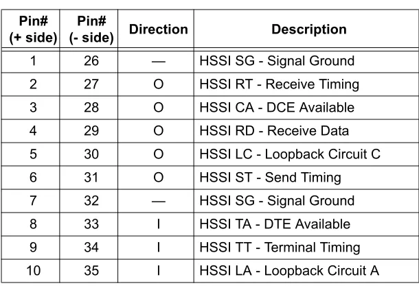
NxT1 HSSI/V.35 Option Module (P/N 1200346L2)
V.35 is possible with the NxT1 HSSI Option Module with an appropriate adapter cable (ADTRAN P/N 3125I081@A); however, some HSSI menu options will be unavailable in this mode (for details, see the User Interface Guide section). Table 27 and Table 28 on page 45 give the pinouts for the V.35 and RJ-48C (T1) connectors, respectively.
Table 26. HSSI (SCSI-II, 50-Pin) Connection Pinout Pin #
(+ side)
Pin #
(- side) Description
Pin # (+ side)
Pin #
(- side) Description
1 26 SG - Signal Ground 10 35 LA - Loopback Circuit A
2 27 RT - Receive Timing 11 36 SD - Send Data
3 28 CA - DCE Available 12 37 LB - Loopback Circuit B
4 29 RD - Receive Data 13 38 SG - Signal Ground
5 30 LC - Loopback Circuit C 14-18 39-43 Ancillary to DCE (Reserved)
6 31 ST - Send Timing 19 44 SG - Signal Ground
7 32 SG - Signal Ground 20-23 45-48 Ancillary to DTE (Reserved)
8 33 TA - DTE Available 24 49 TM - Test Mode
9 34 TT - Terminal Timing 25 50 SG - Signal Ground
Table 27. HSSI/V.35 Connection Pinout Pin#
(+ side)
Pin#
(- side) Direction Description
1 26 — HSSI SG - Signal Ground
2 27 O HSSI RT - Receive Timing
3 28 O HSSI CA - DCE Available
4 29 O HSSI RD - Receive Data
5 30 O HSSI LC - Loopback Circuit C
6 31 O HSSI ST - Send Timing
7 32 — HSSI SG - Signal Ground
ATLAS 550 System Manual Section 2 Engineering Guidelines
11 36 I HSSI SD - Send Data
12 37 I HSSI LB - Loopback Circuit B
13 38 — HSSI SG - Signal Ground
— 39 — Ancillary to DCE (Reserved)
14 — I V.35 RTS - Request to Send
15 40 I V.35 TT Terminal Timing
16 41 I V.35 SD Send Data
— 42 O V.35 DCD - Data Carrier Detect
17-18 43 — Ancillary to DCE (Reserved)
19 44 — HSSI SG - Signal Ground
20 45 O V.35 ST - Send Timing
21 46 O V.35 - Receive Timing
22 47 O V.35 RD - Receive Data
23 — O V.35 CTS - Clear to Send
— 48 I V.35 Ground/Present
24 49 O TM - Test Mode
25 50 — SG - Signal Ground
Table 28. T1 Network Connection Pinout
Pin Name Description
1 RXDATA-RING (R1) Receive data from the network 2 RXDATA-TIP (T1) Receive data from the network 4 TXDATA-RING (R) Send data towards the network 5 TXDATA-TIP (T) Send data towards the network
3,6,7,8 ––––– Unused
Table 27. HSSI/V.35 Connection Pinout (Continued)
Pin# (+ side)
Pin#
Section 2 Engineering Guidelines ATLAS 550 System Manual
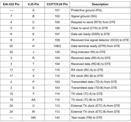
Legacy Data Option Module (P/N 1200342L1), EIA-232 and V.35
The Legacy Data Option Module provides four EIA-232 or V.35 interfaces (or any combination up to four) for synchronous or asynchronous packet data applications. Table 29 gives the pinouts for both the EIA-232 and V.35 connections.
Table 29. EIA-232 and V.35 Connection Pinouts EIA-232 Pin V.35 Pin CCITT/V.24 Pin Description
–– A 101 Protective ground (PG)
7 B 102 Signal ground (SG)
4 C 105 Request to send (RTS) from DTE
5 D 106 Clear to send (CTS) to DTE
6 E 107 Data set ready (DSR) to DTE
8 F 109 Received line signal detector (DCD) to DTE
20 H 108/2 Data terminal ready (DTR) from DTE
22 J 125 Ring indicator (RI) to DTE
3 R 104 Received data (RD-A) to DTE
3 T 104 Received data (RD-B) to DTE
17 V 115 RX clock (RC-A) to DTE
17 X 115 RX clock (RC-B) to DTE
2 P 103 Transmitted data (TD-A) from DTE
2 S 103 Transmitted data (TD-B) from DTE
15 Y 114 TX clock (TC-A) to DTE
15 AA 114 TX clock (TC-B) to DTE
24 U 113 External TX clock (ETC-A) from DTE
24 W 113 External TX clock (ETC-B) from DTE
ATLAS 550 System Manual Section 2 Engineering Guidelines
Octal Ethernet Switch Option Module (P/N 1200766L1), USOC RJ-48C
The Octal Ethernet Switch Option Module provides eight RJ-48C interfaces that can operate as 10BaseT or 100BaseTX. Table 30 gives the pinout for the Ethernet connection.
Table 30. Ethernet RJ-48C Pinout
Pin Name Description
1 TX1 Transmit Positive
2 TX2 Transmit Negative
3 RX1 Receive Positive
4, 5 –––– Unused
6 RX2 Receive Negative
Section 2 Engineering Guidelines ATLAS 550 System Manual
7.
AT-A-GLANCE SPECIFICATIONS
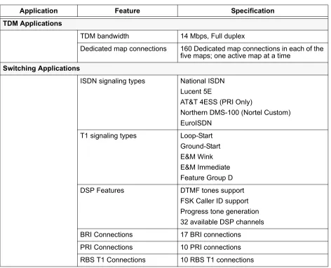
Table 31 lists the specifications for the ATLAS 550 system.
Table 31. ATLAS 550 System Specifications
Application Feature Specification
TDM Applications
TDM bandwidth 14 Mbps, Full duplex
Dedicated map connections 160 Dedicated map connections in each of the five maps; one active map at a time
Switching Applications
ISDN signaling types National ISDN Lucent 5E
AT&T 4ESS (PRI Only)
Northern DMS-100 (Nortel Custom) EuroISDN
T1 signaling types Loop-Start Ground-Start E&M Wink E&M Immediate Feature Group D
DSP Features DTMF tones support
ATLAS 550 System Manual Section 2 Engineering Guidelines
Frame Relay
Packet throughput 4000 pkts/sec (minimum) Management signaling
interfaces UNI (user and network) NNI Management signaling types ANSI T1.617-D (Annex D)
ITU-T Q.933-A (Annex A) LMI (Group of four) Auto
Encapsulation RFC 1490
PVC support 300 PVCs
Congestion control FECN / BECN Discard eligible (DE)
Quality of service (QOS) Prioritization on a per-PVC basis Testing (ADTRAN proprietary) PVC loopback
Round trip delay measurement
SNMP support RFC 1315
PPP
Connection support 100 connections Authentication support PAP
CHAP EAP
Keepalive support On/Off
Interface support Numbered interfaces Unnumbered interfaces IP Routing
Route discovery RIP V1
RIP V2 ICMP ARP IARP UDP Relay
SNMP support RFCs 1155-SMI, 1158-MIB, 1212, 1213, 1215, 1315, 1406
ADTRAN Enterprise MIBs Table 31. ATLAS 550 System Specifications (Continued)
Section 2 Engineering Guidelines ATLAS 550 System Manual
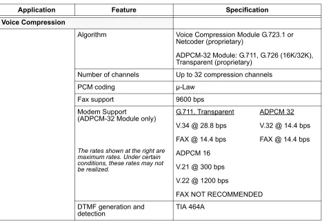
Voice Compression
Algorithm Voice Compression Module G.723.1 or Netcoder (proprietary)
ADPCM-32 Module: G.711, G.726 (16K/32K), Transparent (proprietary)
Number of channels Up to 32 compression channels
PCM coding µ-Law
Fax support 9600 bps
Modem Support
(ADPCM-32 Module only)
The rates shown at the right are maximum rates. Under certain conditions, these rates may not be realized.
G.711, Transparent ADPCM 32 V.34 @ 28.8 bps V.32 @ 14.4 bps FAX @ 14.4 bps FAX @ 14.4 bps ADPCM 16
V.21 @ 300 bps V.22 @ 1200 bps
FAX NOT RECOMMENDED DTMF generation and
detection TIA 464A
Table 31. ATLAS 550 System Specifications (Continued)
NETWORK TURNUP PROCEDURE
Provides shipment contents list, grounding instructions, mounting options, and specifics of supplying power to the unit.
C
ONTENTSIntroduction . . . 50 Tools Required . . . 50 Unpack and Inspect the System . . . 50 Contents of ADTRAN Shipments . . . 50 Grounding Instructions . . . 51 Supplying Power to the Unit . . . 51 AC-Powered Systems . . . 51 DC-Powered Systems. . . 52 Mounting Options . . . 52 Rackmounting the ATLAS 550 . . . 52 Wallmounting ATLAS 550 . . . 53 Installing Network and Option Modules . . . 55 Instructions for Installing the ATLAS 550 Network and Option Modules. . . 55 Module Shipping Contents . . . 55 T1/PRI Network Interface Module (P/N 1200307L1/L2) . . . 55 E1/PRA Network Interface Module (P/N 1200308L1) . . . 56 Modem Management Network Module (P/N 1200341L1). . . 56 BRI DBU Network Module (P/N 1200327L1) . . . 56 Dual/Quad T1/PRI Option Module (P/N 1200314L1/L2 and 1200755L1/L2) . . . 56 Dual Nx 56/64 Option Module (P/N 1200311L1). . . 56 Dual USSI Option Module System (P/N 4200754Lx) . . . 57 Quad Basic Rate ISDN (U-Interface) Option Module (P/N 1200315L1) . . . 57 Quad Basic Rate ISDN (S/T Interface) Option Module (P/N 1200764L1). . . 57 Octal/Quad FXS Option Module (P/N 1200309L1/1200328L1) . . . 57 Octal/Quad FXO Option Module (P/N 1200310L1/1200329L1) . . . 58 Octal E&M Option Module (P/N 1200313L1) . . . 58 Legacy Data Option Module (P/N 1200342L1) . . . 58 NxT1 HSSI Option Module (P/N 1200346L1) with V.35 Support (P/N 1200346L2) . . . 58 Ethernet Switch Option Module (P/N 1200766L1) . . . 58 Resource Host Module (P/N 1200324L1) . . . 59 4,8,16,24 Channel Voice Compression Resource Modules (P/N 1200312Lx) . . . 59 32 Channel ADPCM Resource Module (P/N 1200752L1) . . . 59 Nx 56/64 BONDing Resource Module (P/N 1200326L1) . . . 59
F
IGURESSection 3 Network Turnup Procedure ATLAS 550 System Manual
1.
INTRODUCTION
This section discusses the ATLAS 550 System installation.
2.
TOOLS REQUIRED
The tools required for installation of the ATLAS 550 unit are:
• #2 Phillips-head screwdriver
• Flat-head screwdriver (for installing modules)
3.
UNPACK AND INSPECT THE SYSTEM
The ATLAS 550 is shipped in its own cardboard shipping carton. Open the carton carefully and avoid deep penetration into the carton with sharp objects.
After unpacking the unit, inspect it for possible shipping damage. If the equipment has been damaged in transit, immediately file a claim with the carrier, and then contact ADTRAN Customer Service (see the contact information in the front of this manual).
Contents of ADTRAN Shipments
Your ADTRAN shipment includes the following items. (Shipping contents for the modules begin on page 57.)
• The ATLAS 550 unit
• The ATLAS 550 Product CD
• AC power cord - ADTRAN P/N 3127031 (with AC systems) • 19” rackmount brackets and screws
• RJ-45 to DB-25 adapter - ADTRAN P/N 3196ADPT006
To prevent electrical shock, do not install equipment in a wet location or during a lightning storm.
Electronic modules can be damaged by static electrical discharge. Before handling modules, put on an antistatic discharge wrist strap to prevent damage to electronic components. Place modules in antistatic packing material when transporting or storing. When working on modules, always place them on an approved antistatic mat that is electrically grounded.
ATLAS 550 System Manual Section 3 Network Turnup Procedure
4.
GROUNDING INSTRUCTIONS
The following provides grounding instruction information from the Underwriters’ Laboratory UL60950 Standard for Safety of Information Technology Equipment Including Electrical Business Equipment, Third Edition, of December 1, 2000.
An equipment grounding conductor that is not smaller in size than the ungrounded branch-circuit supply conductors is to be installed as part of the circuit that supplies the product or system. Bare, covered, or insulated grounding conductors are acceptable. Individually covered or insulated equipment grounding conductors shall have a continuous outer finis