Space Launch System Base Heating Test:
Sub-Scale Rocket Engine/Motor Design, Development and
Performance Analysis
Manish Mehta1, C. Mark Seaford2 and Brian C. Kovarik3
NASA Marshall Space Flight Center, Huntsville, Alabama 35812
Aaron Dufrene4 and Nathan Solly5
CUBRC Inc., Buffalo, NY 14201
Robert D. Kirchner6 and Carl D. Engel7
Qualis - Jacobs, Huntsville, AL 35812
The Space Launch System (SLS) base heating test is broken down into two test programs: (1) Pathfinder and (2) Main Test. The Pathfinder Test Program focuses on the design, development, hot-fire test and performance analyses of the 2% sub-scale SLS core-stage and booster element propulsion systems. The core-core-stage propulsion system is composed of four gaseous oxygen/hydrogen RS-25D model engines and the booster element is composed of two aluminum-based model solid rocket motors (SRMs). The first section of the paper discusses the motivation and test facility specifications for the test program. The second section briefly investigates the internal flow path of the design. The third section briefly shows the performance of the model RS-25D engines and SRMs for the conducted short duration hot-fire tests. Good agreement is observed based on design prediction analysis and test data. This program is a challenging research and development effort that has not been attempted in 40+ years for a NASA vehicle.
I. Introduction
A. BackgroundHE
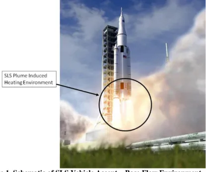
NASA Marshall Space Flight Center (MSFC) Aerosciences Branch is currently responsible for developing ascent plume induced thermal design environments for the Space Launch System (SLS) vehicle (Figure 1). The exhaust plume environments contain both radiation and convection modes of heat transfer. The dominant heat source early in flight is radiation from the large solid rocket motor plumes and to a somewhat less extent from the Core Stage RS-25D (Space Shuttle Main Engine) hydrogen – oxygen plumes. First stage (before booster separation) radiation contributes about 66% of the overall flight heat load. Early in flight, vehicle base elements experienceconvective cooling due to the aspirating nature of the plumes. Later in flight, as altitude increases, and pressure
1 NASA Technical Lead, Aerosciences Branch, MS 3418/EV33, AIAA Member 2 Sr. Aerospace Engineer, Aerosciences Branch, AIAA Member
3
Co-Op Student, Aerosciences Branch, AIAA Member
4 CUBRC Technical Lead, Suite 106, 4455 Genesee St., AIAA Member 5 Engineer, Suite 106, 4455 Genesee St.
6 Sr. Aerospace Engineer, Aerosciences Branch
7 Sr. Aerospace Engineer (retired), Aerosciences Branch, AIAA Member
T
decreases, the plumes expand and begin to interact with each other resulting in reverse flow of hot gases into the base. It is at high altitude where significant plume interaction occurs that the base elements experience peak
convective heat flux. First stage convection contributes about 8% to the overall flight heat load. Second stage flight after booster separation experiences a lower level convective heat flux for a significantly longer period of time, contributing about 23% to the overall base thermal load. In summary, first stage flight experiences peak convective heat flux, while second stage flight experiences the largest convective heat load. Due to the complex nature of these flows, some form of testing is required to mitigate unknown risks.
There are four main reasons that this test is being pursued after almost 40 years with the NASA SLS Program. The first reason is that current computational fluid dynamics (CFD) solutions and semi-empirical methodologies show significant differences in base heating predictions, and it is critical to have accurate and relevant wind tunnel test data as a reference. The second reason is that rocket vehicle base flows exhibit complex flow physics, and purely analytical methods have not been developed for base environment predictions. The third reason is that the SLS vehicle has new base geometry and performance and as a result, the direct usage of heritage data is not recommended. The fourth reason is that accurate prediction of the base flow environments are needed to efficiently size the thermal protection system (TPS).
As a result, the MSFC Aerosciences Branch has decided to develop and plan for a sub-scale Space Launch System (SLS) base heating test to validate our semi-empirical and CFD models of the ascent environments. More importantly, the wind tunnel data will also be used to more accurately predict the space flight environments. Both of these outcomes will decrease mission risk and help design the vehicle base. As a result, the Branch has selected the Calspan-University of Buffalo Research Center (CUBRC) to be responsible for the design, fabrication, test and reduction/verification of the data for both the Pathfinder Test and the SLS Base Heating Test of the SLS Block 1 configuration. The test will be conducted within the CUBRC LENS II facility.
B. Innovative Test Methodologies
There are four new design objectives with the SLS-Base Heating Test (SLS-BHT) which can significantly improve data fidelity. These areas were not pursued for the Saturn and Shuttle Base Heating Test Programs in the 1960s and 1970s. The first area of critical importance is matching the nozzle inner wall boundary layer specific enthalpy between test and flight for both the SRM (booster stage) and RS-25D (core stage) elements. This can be achieved by selecting the appropriate nozzle materials/throat inserts for the two elements and parsing the data at desired time slices determined through analyses. The second area is matching the thrust chamber pressure – altitude profiles for the RS-25D and SRM model elements with the flight engines. The CUBRC facility allows for high gas-feed pressure systems in excess of 6000 psia. The third area is to increase the steady-state test run-time to between 100 and 300 msec by running the CUBRC LENS II facility as a Ludwieg Tube and implementing new tunnel operating methodologies. The fourth area is to use new computational tools and newly developed codes to determine the design and performance of the model engines and motors. These areas will minimize the extrapolation and scaling needed to predict flight environments from the test data. The overarching objective will be to improve data fidelity. These methodologies will also minimize test cost and schedule risks.
Figure 1. Schematic of SLS Vehicle Ascent – Base Flow Environment.
C. CUBRC LENS II Facility
The SLS-BHT will focus on both the high heat flux first stage integrated vehicle period of flight illustrated in Figure 1, as well as the second stage high heat load period of flight. The CUBRC LENS II shock tunnel is currently capable of operating over a Mach range of 3.0 ≤ M∞ ≤ 15.0 and pressure altitudes of sea-level ≤ H ≤ 200 kft. The CUBRC LENS II Ludwieg Tunnel operates at M∞ = 2.5 and pressure altitudes between 30 kft to 120 kft.
Two test programs will be conducted within the facility: (1) a Pathfinder Test which will determine whether the propulsion system elements (core and booster) of the sub-scale model operate successfully and match the similarity parameters to flight conditions; (2) the all up SLS Base Heating Test with the vehicle outer mold line geometry will be conducted by running the shock tunnel at the proper Mach numbers and ambient pressure conditions to simulate various flight conditions.
D. Pathfinder Test Program Requirements
Primary
1. Verify test model system and instrumentation response times and electrical continuity.
2. Measure the propulsion internal flow path state parameters (pressure, temperature and gas velocity) of the core-stage and booster elements.
3. Measure thrust chamber pressure and temperature temporal distributions for the model RS-25D and SRM elements.
4. Measure the inner nozzle wall temperature and heat flux (if practical)-time history and axial distribution for both the model SRM and RS-25D for different nozzle inserts/material (3 types for the model RS-25D and 3 types for the model SRM).
5. Determine which nozzle insert/material for both the model SRM and RS-25D show similarity in the nozzle boundary layer specific enthalpy between flight and test.
6. Verify if the thermography/pyrometer techniques are adequate to obtain nozzle wall temperature distributions.
Secondary
E. SLS Base Heating Test Program Requirements
Primary
1. Verify the adequacy and degree of conservatism of the SLS base convective thermal design environments for various base region hardware elements in support of the March, 2015 Critical Design Review (CDR). The test shall simulate altitude increments between 50 and 145 kft for the first stage configuration, and between 145 kft and 200 kft for the four engine core second stage. The vehicle outer mold line of the test will be based on geometry of the SLS Block 1 configuration.
2. Measure convective heat flux and pressure distributions on the core base heat shield, Solid Rocket Booster thermal curtain region, and the model RS-25D and SRM nozzles.
3. To the extent practical measure base gas recovery temperature at various locations. Secondary
4. To the extent practical measure convective heat flux and pressure distribution changes for a single model RS-25D engine-out case.
5. Measure radiative heat flux on the base heat shield and nozzle external walls.
II. Model Core-Stage Propulsion System Design
The core-stage propulsion system for the test model is perhaps the most complex component of this test model. There are various hardware components that need to be designed and fabricated to ensure proper operation of the core-stage engines. The major components of the core-stage propulsion system are: the charge tubes, quick-acting expansion valve, venturis, injector manifold, injectors, central combustion chamber, ports and nozzles. For the model RS-25D engines, the two propellants used are gaseous hydrogen as the fuel and gaseous oxygen as the oxidizer. A sketch of this system is shown in Figure 2.
Figure 2. Schematic of the model core-stage propulsion system.
sized to produce the required flight engine oxidizer to fuel (O/F) ratio. The propellants then pass through the injectors and quickly combust within the central combustor. The combustion exhaust products pass through the ports and accelerate through the converging-diverging nozzles to provide the required nozzle exit properties.
The pressure distribution along the gaseous oxygen and hydrogen systems was initially calculated by the semi-empirical Qualis/MSFC Impulse Combustion Excel (ICE) engineering code [1]. The QICE code generates geometrical dimensions, and steady-state pressure and Mach number distributions within the overall gas delivery system. The QICE code was developed from heritage Saturn and Shuttle base heating test data and then modified for the current application. QICE provided an initial model design that was further refined using more rigorous CFD and thermal model analysis as defined below.
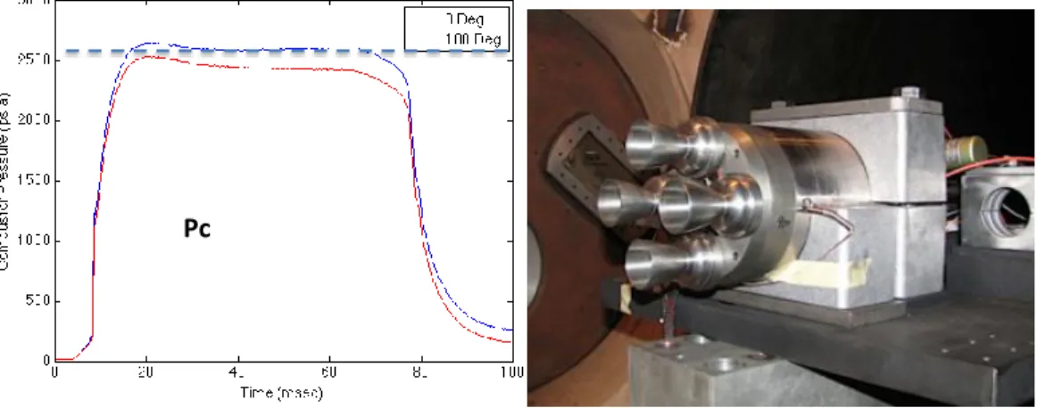
The pressure–time histories are important to characterize for a short duration test on the order of 150 msec. Since we are constrained by the test run-time, a relatively quick response time is needed to adequately perform the test. Also, the flow path and flow field determination is needed to assess the performance of the design. As a result a 1-D transient, finite-rate chemistry conservation of mass, momentum and energy model was developed. Also, the model core-stage propulsion system was modeled in 3-D using the Loci-CHEM CFD solver [2]. Various design iterations were modeled using CFD, and the highest performing model engine which met design requirements was selected for fabrication. As can be seen Figure 3, the thrust chamber pressure reaches steady-state in less than 20 msec, which we define as the model time constant tau. The other very important requirement is that the combustion chamber pressure remains steady during the entire firing duration. The steady Pc value reached ~90% of the full-scale value, and further performance increases are not being pursued due to model nozzle throat erosion and safety concerns. This design and performance analysis shows that all the design requirements have been satisfied. The steady-state CFD solution is shown as a dotted blue line in Figure 3, and is in good agreement with two test pressure
measurements on opposite radial ends of the combustor. Moreover, these two pressure measurements demonstrated the uniformity of the flow within the combustor.
Figure 3. Core-stage central combustor pressure vs. test run time (left) and model core-stage engine (right).
III. Model SRM Propulsion System Design
The next topic is the initial design and analyses of the model solid rocket motor (SRM) propulsion system illustrated in Figure 4. The combustion chamber of the model SRM was designed using a transient 1-D engineering analysis conservation of mass code developed for this test. The propellant that will be used is AeroTech’s Propellant X or Mixture 1, which is very similar in composition to the Space Shuttle Reusable Solid Rocket Motor (RSRM) propellant and contains ~16% by mass aluminum as the fuel. The AeroTech cartridges are cylindrical and bored through the middle. Combustion is initiated by igniting a torch. There are two design constraints when deciding on the cartridge length (Lc). If the combustion chamber is too long with dead space (not containing propellant), this will lead to much larger response times or tau. If the combustion chamber is too small and has no modifications to the manufactured cartridge, the burn surface area will be too small, decrease the chamber pressure, Pc, and not produce the desired combustion chamber properties.
Upstream
Valve
Pc
Venturi
RUN18
Plenum
The 1-D transient SRM Pc code was used to design the cartridge dimensions. In the upper left panel of Figure 5 is shown the predicted Pc-time history, which exhibits a short tau for a desired Pc of ~600 psia. The corresponding propellant thickness time history is shown in the lower left panel of Figure 5. Design iterations based on
performance analyses, as well as trial-and-error approaches based on hot-fire testing, were used to finalize the model SRM design (shown in Figure 6). In the upper right panel of Figure 5 is the hot-fire test data for the model SRM head-end pressure gauge. All design requirements are satisfied. Good agreement is observed between the 1-D model and test data.
Figure 4. Schematic of the model SRM combustion chamber and cartridge.
Figure 5. Model SRM chamber pressure vs. test run time for model results (left) and hot-fire test data (right).
Test Data Model Results
SRM Test Run 006
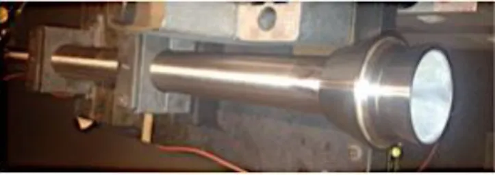
CERAMIC COATED NOZZLE
Figure 6. Model SRM.
IV. Conclusions
Final model engine and motor designs were developed from extensive design and analyses efforts to minimize cost and schedule risks. Innovative methodologies and analyses were incorporated to increase the fidelity of the test data for the base heating test.
The main design requirements based on test data performance analysis are satisfied such as: (a) the combustion chamber pressure is within ~90% of the full-scale value; (b) the ignition time-scales are less than 35 msec; (c) the firing duration is greater than 100 msec; (d) steady chamber pressure is observed; (e) the O/F ratio, injector exit Mach number and pressure loss ratio are in good agreement with the design requirements; (f) repeatability in the performance is observed; (e) no observation of nozzle throat/combustor erosion.
Acknowledgements
We would like to thank Dr. Christopher I. Morris, Aerothermal Team Lead of the NASA MSFC Aerosciences Branch, and Mark D’Agostino, Aerosciences Branch Chief, for technical review of the manuscript.
References
[1] Engel, C.D. et al, (1998), “Qualis Impulse Combustion Excel Application for Launch Vehicle Base Heating Simulation”, SBIR Contract NAS8-97020, Qualis Corporation, Huntsville, AL.
[2] Luke, E. and T. George (2005), "Loci: A Rule-Based Framework for Parallel Multidisciplinary Simulation Synthesis,"
Journal of Functional Programming, Special Issue on Functional Approaches to High-Performance Parallel Programming, Volume 15, Issue 03, 2005, pp. 477-502.