ISSN 1330-3651 (Print), ISSN 1848-6339 (Online) DOI: 10.17559/TV-20150221215735
EFFECT OF PULSE LASER ENERGY DENSITY ON TiC CLADDING OF ALUMINIUM
SUBSTRATE
Janez Sušnik, Janez Grum, Roman Šturm
Original scientific paper In this work, TiC cladded layer has been produced by laser scanning over the preplaced TiC powder on aluminium substrate, using a pulse Nd:YAG laser. Depending on the effective energy density at the specimen surface, TiC was deposited or partially dispersed into the melted aluminium at the specimen surface. Microstructure was evaluated using optical microscopy and SEM/EDS analysis. Depth of laser cladded layer and microhardness measurements have been deliberated at the cross-section of laser cladded specimens. Effect of pulse laser energy density on cladding layer depth, microhardness, surface roughness and waviness has been studied. From the experimental analysis it is revealed that effective energy density has a significant effect on the TiC cladded surface roughness and waviness, but very little on microhardness of the cladded layer.
Keywords: aluminium; cladding; energy density; pulse laser; TiC
Učinak gustoće pulzirajuće energije lasera na oblaganje aluminijske podloge TiC-om
Izvorni znanstveni članak U ovom je radu sloj obložen TiC-om proizveden skeniranjem laserom preko prethodno položenog praha TiC-a na aluminijsku podlogu pomoću pulzirajućeg Nd:YAG lasera. Ovisno o efektivnoj gustoći energije na površini uzorka, TiCje položen ili djelomično raspršen u rastaljeni aluminij na površini uzorka. Mikrostruktura je određena pomoću optičkog mikroskopa i SEM/EDS analize. Dubina obloženog sloja i mjerenja mikrotvrdoće određena su na poprečnom presjeku uzoraka oblaganih pomoću lasera. Analizirao se učinak gustoće pulzirajuće energije lasera na dubinu oblaganja sloja, mikrotvrdoću, površinsku hrapavost i valovitost. Eksperimentalna analiza je pokazala da efektivna gustoća energije značajno utječe na hrapavost i valovitost površine obložene TiC-om, ali vrlo malo na mikrotvrdoću obloženog sloja.
Ključne riječi: aluminij; gustoća energije; oblaganje; pulzirajući laser; TiC 1 Introduction
The role of laser technology has intensively increased in surface engineering. In practice, various laser melting procedures can be effectively used in creation of functional parts. The most important laser processes are as follows: laser-heat treatment, laser remelting, laser cladding and laser alloying [1].
Laser-assisted coating is a surface modification process characterized by high processing speed, controlled precision, and by its applicability. In the literature, it is found that for most of the cases a coating of hard ceramic particles forms a protective layer, which significantly improves the strength, stiffness and wear resistance of the bulk components [2 ÷ 6]. Laser cladding is a process which provides enough engineering thickness and excellent bonding with the substrate. Due to the minimized heat conduction into substrate, laser cladding technique shows extraordinarily distinct advantages such as negligible distortion, low dilution, high hardness, narrow heat affected zone (HAZ) and reduced cracking susceptibility. Laser cladding with pre-placed powder is a simple and versatile method provided the powder can be made to remain in place until melted. For this reason some form of binder is usually used and the laser beam is scanned over the powder bed paste [1, 3, 5, 6]. The general theory for cladding of pre-placed powder can be based on the work of Powell et al. [7]. The absorption of laser power is dependent on the materials and their surface condition of the preplaced layer. According to Deng et al. [8] the absorption of the preplaced layer is always assumed as a constant which should be in the range from 0,2 to 0,3. Even though the TiC melting temperature is higher than the boiling point of aluminium, this can be possible as the absorption coefficient of TiC at
the laser wavelength is three times than the one of aluminium, as described by Lietchi et al. [9]. Consequently, the TiC particles can be melted during the injection, while the Al powder is not boiled, leading to the Al4C3 precipitation in the molten pool.
Lei et al. [10] have proposed a new three-dimensional model to simulate the high power laser clad TiC composite coatings using commercial finite element analysis software. Jianing et al. [11] discussed the microstructure, micro-hardness and phase constitutes in the Al+TiC laser cladding layer deposited on Ti–6Al–4V alloy by adding different TiC contents. Although there was a great temperature gradient between the laser cladding layer and substrate, there was a metallurgical bond between the laser cladding layer and Ti–6Al–4V substrate. When the mass percent of TiC was 40 %, the micro-hardness of cladding layer may be up to 3 times more than that of the substrate. Kadolkar et al. [12] have found for TiC coatings and for the range of processing parameters employed, the residual macro-stresses were compressive in nature. The residual micro-stresses in the Al matrix of the coating were tensile, whereas those in the TiC particles were compressive. The most important industrial use of TiC is for wear-resistant applications. Most of researchers study the effect of laser scanning speed of continuous lasers on size and morphology of cladded layer. Ochonogor et al. [13] found that grains of titanium carbide were uniformly distributed throughout the metal matrix which contributed to excellent level of resistance to wear and increase in the hardness value. And they have not found any correlation between hardness and abrasive wear due to differences in composition. Duraiselvam et al. [14] discussed the influence of hardness of TiC laser cladded layers on erosion resistance. The co-existence of cavitation erosion resistant
Effect of pulse laser energy density on TiC cladding of aluminium substrate J. Sušnik et al. intermetallics in a carbide reinforced matrix was
responsible for the improved erosion resistance and the failure mode of the eroded area was characterized as brittle fracture. Dubourg et al. [15] described laser cladding of MMC coatings on aluminium substrate. The microstructure of the coatings was homogeneous and free of pores or cracks. Carbides were uniformly distributed throughout the coating cross-section. Ravnikar et al. [5, 6] obtained a coating with TiC and TiB2 particles of various
shapes and sizes embedded in an Al matrix. Thermal effects of the coating process and rapid cooling contributed to the occurrence of forced dissolution with reduced microhardness. Even though the average microhardness of the coating is about 40 % higher than the substrate hardness. The coating shows exceptional wear resistance.
Melting ratio is known as a suitable factor to illustrate the effects of process parameters on the clad profile in order to provide a proper process design. However, the definition of melting ratio based on continuous irradiation of energy does not accommodate for pulse parameters. It is established that energy density and interaction time are two essential parameters in laser cladding process which affect the clad profile the most [16]. Farnia et al. [17] showed that the effects of pulse duration and overlapping factor are different at low and high values, and therefore it is difficult to find optimum values for pulse duration and overlapping factor to achieve maximum efficiency in preplaced pulsed laser cladding process.
2 Materials and methods
2.1 Selection of base aluminium alloy and cladding powder The chemical composition of the selected hypo-eutectic aluminium AlSi12CuNiMg alloy (ISO) is: 12 Si; 0,93 Cu; 0,9 Ni; 1,04 Mg; in wt. %, Al balance. The aluminium alloy was used in delivered state, i.e. as-cast state with additional homogenization heat treatment. Heat treatment contains hardening to maximum strength by solution heat treatment at 520 ÷ 530 °C for 5 ÷ 10 hours, followed by quenching and artificial ageing at 150 ÷ 175 °C for 5 ÷ 15 hours.
Figure1 Microstructure of as-cast AlSi12CuNiMg alloy, etched The selected alloy AlSi12CuNiMg is hypo-eutectic and containing inter-dendritic network of eutectic silicon with different intermetallic compounds which improve alloy micro-hardness. Intermetallic compounds are Mg2Si
(black script), Al6Cu3Ni (light-grey script) and Al3Ni
(dark-grey script). The alloy AlSi12CuNiMg shows micro-hardness of around 100 HV0,2. The selected
hypo-eutectic alloy AlSi12CuNiMg shows tensile strength of around 280 MPa and microhardness of around 100 HV0,2.
The microstructure is shown in Fig. 1.
The cladding material was TiC powder with a purity of 99,5 %. The diameter of TiC powder particles was between 4 and 8 µm. The powder was obtained from Global Tungsten & Powder Corp., Towanda, USA. Dimensions of aluminium specimens prepared for laser cladding were 65 × 20 × 2,5 mm3. The specimen surface
was grinded by emery paper 800 prior applying TiC cladding powder (TiC, 100 wt.%) to the surface in order to eliminate the existence of thick oxides. A thin layer of pre-paste TiC powder (with approximate thickness of 0,15 mm) was applied on the substrate surface by air gun. For better adhesion of TiC powder to the substrate surface, TiC powder was mixed with alcohol to form a sort of a wet paste.
2.2 Laser surface cladding
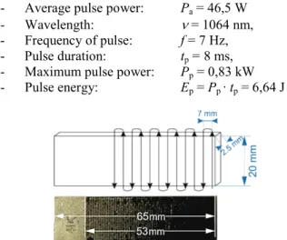
An unconventional approach using pulsed Nd:YAG laser which is typically used for welding was chosen to investigate the suitability of this technique for the surface cladding. Procedures using pulsed Nd:YAG laser could act as a cost-effective tool of advanced surface engineering or when effective repair procedure of damaged surface during its exploitation is needed, or both. The laser surface cladding was performed on specimens by means of OR Laser, type: ECO BU80 Nd:YAG laser with a maximum mean power of 80 W and top hat mode structure, using the following experimental parameters:
- Average pulse power: Pa = 46,5 W
- Wavelength: ν = 1064 nm,
- Frequency of pulse: f = 7 Hz, - Pulse duration: tp = 8 ms,
- Maximum pulse power: Pp = 0,83 kW
- Pulse energy: Ep = Pp ∙tp = 6,64 J
Figure 1 Laser beam movement across the specimen surface In our experiment we were changing laser beam travelling speed and defocus – beam diameter on the specimen surface. Laser beam changed its movement at a distance of 0,7 mm, as it is represented in Fig. 1. Laser beam changed the direction of movement outside the specimen. Argon protective gas of the 99,995 % purity and flow rate of 5 l/min was used during the whole process to minimize surface oxidation.
The following laser beam parameters were used: - Beam travel speed: vb = 100; 150 mm/min
- Beam diameter on the specimen surface: Db= 0,82;
- Laser path overlapping: 𝑂𝑂p=0𝐷𝐷,7b∙100 % = 85; 70;
59 %
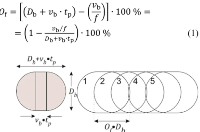
Overlapping factor Of between laser pulses is defined
in Fig. 2 and in Eq. (1) [17, 18], and results are shown in Tab. 1.
𝑂𝑂f=��𝐷𝐷b+𝑣𝑣b∙ 𝑡𝑡p� − �𝑣𝑣𝑓𝑓 �� ∙b 100 % =
=�1− 𝑣𝑣b⁄𝑓𝑓
𝐷𝐷b+𝑣𝑣b∙𝑡𝑡p� ∙100 %
(1)
Figure 2 An overlapping factor defined in a pulsed laser process For this study, laser peak power was set to be PP =
0,83 kW. Combination of pulse duration and pulse frequency was chosen in such a way that average power did not reach the limit of Nd:YAG laser system used.
Due to pulse nature of beam, energy density (ED) and effective energy density (EED) were also calculated to find out the energy input per pulse and total energy input during laser processing [17,18]:
𝐸𝐸𝐷𝐷=𝐸𝐸𝑃𝑃 𝐴𝐴 (J/mm 2) (2) 𝐸𝐸𝐸𝐸𝐷𝐷=𝐸𝐸P∙𝐹𝐹 𝐴𝐴 (J/mm 2) (3)
where A (mm2) is area of laser spot on specimen, F is the
cumulative overlapping index defined as:
𝐹𝐹= 1 +𝑛𝑛 ∙ �1−(𝑛𝑛+ 1)∙ 𝑣𝑣b/(2∙ 𝑓𝑓 ∙ 𝐷𝐷b)� (4)
𝑛𝑛=𝐷𝐷b∙𝑓𝑓
𝑣𝑣b (5)
The results of the calculated effective energy density at the surface of cladding powder are presented in Tab. 1.
Table 1 Overlapping factor Of (%) between laser pulses and the calculated effective energy density EED (J/mm2) at the specimen surface
Beam diameter (mm)
Laser beam travel speed (mm/min)
100 150 Of (%) (J/mmEED2) Of (%) (J/mmEED2) 0,82 71 28 / / 1,0 77 22 65 16 1,18 80 18 / / 2.3 Metallography
For the metallographic characterization the specimens were ground and polished according to standard metallographic procedures. The top-view specimens and the cross-sections of the laser cladded samples were prepared. In order to reveal the microstructure the
samples were chemically etched using an aqueous solution of 1 ml HF + 2 ml HCl + 3 ml HNO3 + 94 ml
H2O.
The measurements of the maximum depth of the laser-cladded zone, melted and the heat-affected zone were made using light microscopy. The metallographic examinations were performed using also field-emission scanning electron microscopy. In FE-SEM/EDS analyses the teardrop-shaped interaction volume depends on the element and the accelerating voltage. In this study, the FE-SEM/EDS analyses were performed at a 10 kV accelerating voltage. Other factors that determine the detection limits of the EDS are: the counting time, the beam current, the line used to measure the element and the compositions of both the sample and the standards. 2.4 Microhardness
Microhardness was measured in accordance with the Vickers method, i.e. diamond pyramid hardness measurement, through the depth of the alloyed layer. Hardness was measured at a load of 200.g on metallographically polished, cross-section samples of laser cladded specimen.
In addition to the mentioned method the microhardness measurements were also performed separately in the matrix of the clad material at a load of 25 g.
2.5 Surface roughness and waviness
The surface roughness (Ra) and waviness (Wa) were measured using a profilemeter Surtronic 3+, Taylor-Hobson, with a sampling length of 8 mm and measurement speed of 0,5 mm/s. We have used Gaussian filter with a 3 mm sample range cut. The Ra and Wa values were calculated by averaging five measurement values obtained from five different locations of cladded surface.
3 Results and discussion 3.1 Microstructure
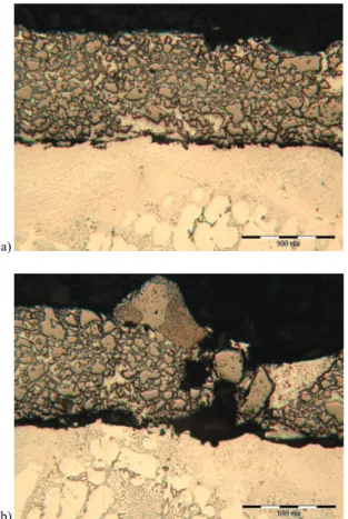
Laser surface cladding of the given aluminium alloy with TiC powder or particulates produced a characteristic microstructure, shown in Fig. 3. The specimen was coated with an average laser peak power density of 0,759; 1,057 and 1,572 kW/mm². In Fig. 3a we can notice three different zones: laser surface cladded zone, laser melted aluminium substrate, and base metal. There is an unexpressive heat affected zone between melted material and base metal. Average thickness of laser cladded layer is around 108 µm, in the range between 22 and 250 µm. Average thickness of melted aluminium beneath laser cladded layer is around 135 µm, in the range between 50 and 220 µm. In Fig. 3b we can observe porosity between laser cladded layer and substrate. Porosity is present also in the cladded layer, and it affects surface roughness too. Uenishi et al. [20] claimed that to obtain TiC clad layer well bound with Al base metal, laser power should be supplied enough to melt not only cladding powders but Al base metal superficially. At TiC laser cladding with
Effect of pulse laser energy density on TiC cladding of aluminium substrate J. Sušnik et al. continuous laser almost no porosity was observed [13, 15,
19].
a)
b)
Figure 3 Microstructure of TiC laser surface cladding, etched In Tab. 2 is presented correlation between Db, Of,
EED, and dimensions of laser cladded surface. We can notice a little decrease of cladded layer dimensions with
decrease of EED. But the decrease in dimension is not in correlation with decrease in EED. Farnia et al. [17] showed that the effects of pulse duration and overlapping factor are different at low and high values. When pulse duration increases, the interaction time between laser beam and the material increases which results in a decrease in EED.
Table 2 Dimensions of TiC modified surface at laser beam travel speed 100 mm/min
Db
(mm) (%) Of (J/mmEED 2) Cladded zone (µm) Melted zone (µm)
0,82 71 28 101 ± 20 150 ± 40
1,0 77 22 139 ± 75 137 ± 30
1,18 80 18 99 ± 45 55 ± 50
The region under the resulting coating is known as the laser melted zone (LMZ). Detailed measurements of the thickness of the laser melted zone revealed that the thickness increased a little with increasing energy input. The laser melted zone illustrates a cellular dendritic microstructure, typical of cast aluminium alloys. The same structure was found also by Ravnikar et al. [6] at continuous laser cladding of aluminium alloy.
The whole modified layer depth remains around 240 ± 50µm in the case of selected laser cladding parameters. In the transition between LMZ and base material there is heat affected zone (HAZ). The region is hard to distinguish, because changes on microstructure are in very small scale and were estimated between 4 µm and 25 µm. Sahoo et al [18] discovered that increase in overlapping factor and laser peak power increase the laser processed composite layer depth and width.
Figure4 SE image of TiC cladded surface layer. The corresponding X-Ray elemental mappings show the distribution of Al, Si, Ti and C In Fig. 4 the distribution of elements is shown in the
of the substrate as well as a part of the matrix material around facets in the laser cladded zone. Carbon and titanium were found to occupy position in the facets which indicate the presence of TiC. Du et al. [21] have according to their results concluded that the rectangular facets are related to the presence of TiB2 and the spherical
ones with TiC. With our research we cannot confirm Du’s conclusions regarding shape of TiC facets.
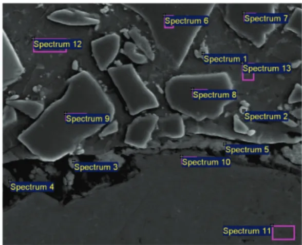
Qualitative analysis of the cladded surface with TiC powder was performed in designated measuring positions, illustrated in Fig. 5.
Figure 5 Selected and measured regions using EDS analyses of TiC cladded surface
Using EDS analysis, seven elements were identified in the coating: Al, Ti, C, O, Si, Mg and Cu. Tab. 3 shows individual measuring positions in the coating with various elements, on the basis of which the presence of different phases may be inferred. The presence of C and Ti in bigger facets designated with spectrum 6, 7, 8 and 9 indicated the existence of TiC.
Table 3 EDS analysis from Fig. 5 (results are given in wt.%)
Spectrum C O Mg Al Si Ti Cu 1 21,94 / / 16,54 2,65 57,16 1,70 2 20,47 / / 20,35 5,61 52,63 0,95 3 15,72 25,86 2,42 53,23 1,69 1,09 / 4 9,89 40,30 4,48 44,26 1,08 / / 5 5,15 13,71 0,67 78,19 1,51 0,77 / 6 21,74 / / 0,55 0,27 77,44 / 7 21,06 / / 0,64 / 78,30 / 8 20,50 / / 0,66 / 78,84 / 9 21,30 / / 0,70 / 78,00 / 10 2,87 2,91 5,10 71,59 16,09 / 1,45 11 2,49 0,79 5,28 77,60 13,85 / / 12 3,83 1,17 / 84,39 8,03 1,50 1,08 13 2,30 0,81 / 78,29 16,38 1,52 0,70
In smaller facets designated with spectrum 1 and 2 we can find also Al and some Si which shows on dissolution of TiC in aluminium matrix and formation of new phases like Al4C3 and Al3Ti [5, 6, 19]. In a similar
TiC cladded layer Jianing et al. [11] have found also Ti3Al and TiAl phases. The reinforcement of the laser
cladding layer was mainly contributed to the action of Ti3Al/Al3Ti + TiC hard phases [11]. Dubourg et al. [15]
have stated that Al4C3 carbide precipitation bust is
avoided due to the brittleness of Al4C3 phase surrounding
the TiC reinforcement. Spectrum 12 and 13 indicated
melted substrate material which due to the capillary effect during the cladding process fills the pores between ceramic components.
A sufficiently high energy density causes the dissolution of TiC in this aluminium substrate. Between laser cladded zone and aluminium substrate in spectrum 3, 4 and 5 carbon and aluminium were found as well as oxygen and small amounts of titanium and silicon. This could affect the occurrence of aluminium oxycarbide. 3.2 Microhardness
Average microhardness measurements were performed with a 200 g load in the middle of a cladded layer, and in the middle of the melted layer. The average microhardness of TiC laser cladded layer is about 850 ± 570 HV0,2. Average microhardness of TiC cladded layer
is independent of selected laser processing parameters. Sahoo et al. [18] found out that average microhardness value of the TiC composite layer is considerably high for using lower peak power but uniformity in the hardness value is less. At higher peak power relatively low but uniform hardness value was obtained [18]. In addition to this Ochonogor et al. [13] have discovered that there is no correlation between hardness and abrasive wear due to differences in composition. Microhardness in the melted layer is much lower than in the cladded layer. It is around 164 ± 20 HV0,2 which is higher than the microhardness of
the base substrate material of 100 HV0,2.
Because of relatively homogeneous structure in base substrate material and in melted layer standard deviation of microhardness values is low. Quite the opposite is standard deviation of microhardness measurements in TiC laser cladded layer. Due to mixture of hard TiC facets surrounded by soft aluminium matrix is standard deviation of hardness measurements reasonably high. The cladded layer contains about 62 % of carbides and 29 % of aluminium as metallic bound, as it is shown in cross-section of cladded layer in Fig. 6.
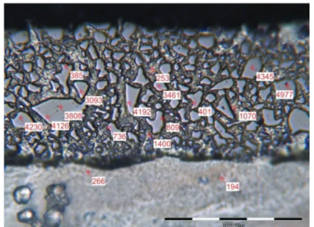
Figure 6 Analysis of the aluminium presence in the cladded layer For better microstructure evaluation in TiC laser cladded layer, microhardness measurements with a load of 25 g were performed at specific structure constituents. From the results presented in Fig. 7 we can establish that there is a great variety of microhardness values. TiC facets reach microhardness values between 3000 and 5000 HV0,025. The aluminium matrix around TiC facets
has microhardness around 250 HV0,025, and microhardness
of some small facets in this matrix is between 400 and 1400 HV0,025.
Effect of pulse laser energy density on TiC cladding of aluminium substrate J. Sušnik et al.
Figure 7 Microhardness (HV0,025) of the structure in the TiC laser cladded layer
3.3 Surface roughness and waviness
In this study beam diameter, laser beam travel speed and beam overlapping factor are chosen as laser parameters to be optimized for reducing average surface roughness (Ra) at laser surface cladding of TiC powder over aluminium alloy. The surface roughness values (Ra) obtained in laser cladding of aluminium alloy according to laser beam diameter, laser beam travel speed and laser beam overlapping factor are shown in Tab. 4.
Table 4 Surface roughness Ra of laser cladded surface with TiC powder Db
(mm) (mm/min) vb (%) Of to laser path Ra (µm) ⊥ to laser path Ra (µm)
0,82 100 71 9,32 5,42
1,0 100 77 10,30 11,70
1,18 100 80 11,60 13,50
1,0 150 65 15,20 11,70
Figure 8 Surface roughness Ra of laser cladded surface As seen from Tab. 4, the Ra values show irregular tendency. Laser beam travel speed increase influences the increase of the Ra. In other words, when we decrease beam overlapping factor, the Ra values increase. But when we observe another combination of laser parameters, we can find out that increasing laser beam diameter influences the increase of Ra. In other words, when we increase beam overlapping factor, the Ra values increase. So in Tab. 4 we cannot find any correlation between laser beam parameters and Ra values of cladded surface. But when we compare Ra values with effective energy density (EED), we find good correlation (Fig. 8).
When we increase EED from 16 to 28 J/mm2, the surface
roughness Ra decreases in both directions parallel with and perpendicular to laser paths. The highest Ra value has been observed as 15,20μm at EED=16 J/mm2, and the
lowest as 5,42 μm at EED=28 J/mm2. So we can state, the
dominant factor affecting the Ra is EED. Very similar statement was expressed by Sahoo et al. [22] who discovered that overall energy input causes better mixing of the preplaced TiC powder with Al substrate material.
Waviness (Wa) is the average of the peak heights of the surface after the roughness values used to calculate Ra have been removed, and therefore represents the larger scale rippled surface texture.
In the case of laser cladding of TiC powder a decrease in the surface roughness is clearly observed when increasing EED. The waviness however does not share the trend of the Ra roughness with changing EED.
The surface waviness values (Wa) obtained in laser cladding of aluminium alloy according to laser beam diameter, laser beam travel speed and laser beam overlapping factor are shown in Tab. 5. The maximum surface waviness is less than 63 µm and minimum Wa=15 µm. It is evident that with increasing EED, the surface waviness tends to increase (Fig. 9).
Table 5 Surface waviness Wa of laser cladded surface Db
(mm) (mm/min) vb (%) Of to laser path Wa (µm) ⊥ to laser path Wa (µm)
0,82 100 71 46,8 49,14
1,0 100 77 38,1 44,2
1,18 100 80 62,6 46,9
1,0 150 65 38,1 15,1
The cladded surface is characterized by waviness Wa = 40 ± 20 µm and roughness Ra = 10 ± 6 µm. Wa is gradually increasing when EED is increasing, and on the contrary Ra is evidently decreasing when increasing EED.
Figure 9 Surface waviness Wa of laser cladded surface 4 Conclusions
A hard layer of TiC was deposited on aluminium AlSi12CuNiMg alloy substrate after laser irradiation over TiC preplaced aluminium surface using Nd:YAG laser. In this research we have used different laser processing parameters. From the experimental analysis the following conclusions can be drawn:
16 18 20 22 24 26 28 5 6 7 8 9 10 11 12 13 14 15 16 trend l ine Ra ( µ m) EED (J/mm2)
parallel with laser path perpendicular to laser path
16 18 20 22 24 26 28 10 15 20 25 30 35 40 45 50 55 60 65 trend line W a ( µ m) EED (J/mm2)
parallel with laser path perpendicular to laser path
• Microstructure of cladded layer is composed of TiC facets surrounded by aluminium matrix. The adhesion between laser cladded layer and melted substrate beneath it is weak due to presence of porosity.
• The average microhardness of cladded layer is 850 ± 570 HV0,2. TiC facets reach microhardness values
between 3000 and 5000 HV0.025.
• Pulse laser parameter i.e. effective energy density (EED) defined with pulse energy, laser spot area and cumulative overlapping index has great influence on the formation of TiC cladded layer.
• Surface roughness (Ra) is decreasing with increasing effective energy density (EED) of laser beam at the surface.
• Surface waviness (Wa) is increasing when effective energy density (EED) of laser beam at the surface is increasing.
• Proper combination of peak power, overlapping factor and pulse duration is required to create a defect-free and uniform coating using pulse laser. 5 References
[1] Major, B. Laser processing for surface modification by remelting and alloying of metallic systems. Pauleau, Y. (ed.) Materials surface processing by directed energy techniques. Elsevier, Amsterdam, (2006), pp. 241-274. DOI: 10.1016/b978-008044496-3/50008-3
[2] Dua, B.; Paital, S. R.; Dahotre, N. B. Synthesis of TiB2–
TiC/Fe nano-composite coating by laser surface engineering. // Optics & Laser Technology. 45, (2013), pp. 647-653. DOI: 10.1016/j.optlastec.2012.05.017
[3] Masanta, M.; Shariff, S. M.; Choudhury, A. R. A comparative study of the tribological performances of laser clad TiB2–TiC–Al2O3 composite coatings on AISI 1020 and
AISI 304 substrates. // Wear. 271, (2011), pp. 1124-1133.
DOI: 10.1016/j.wear.2011.05.009
[4] Masanta, M.; Shariff, S. M.; Choudhury, A. R. Evaluation of modulus of elasticity, nano-hardness and fracture toughness of TiB2–TiC–Al2O3 composite coating developed
by SHS and laser cladding. // Materials Science and
Engineering. A 528, (2011), pp. 5327-5335. DOI:
10.1016/j.msea.2011.03.057
[5] Ravnikar, D.; Dahotre, N. B.; Grum, J. Laser coating of
aluminum alloy EN AW 6082-T651 with TiB2and
TiC:Microstructure and mechanical properties. // Applied
Surface Science. 282, (2013), pp. 914-922. DOI:
10.1016/j.apsusc.2013.06.089
[6] Ravnikar, D.; Mrvar, P.; Medved, J.; Grum, J. Microstructural analysis of laser coated ceramic components TiB2 and TiC on aluminium alloy EN
AW-6082-T651. // Strojniški vestnik - Journal of Mechanical Engineering. 59, 5(2013), pp. 281-290. DOI: 10.5545/sv-jme.2012.904
[7] Powell. J.; Henry, P. S.; Steen, W. M. Laser cladding with pre-placed powder: analysis of thermal cycling and dilution effects. // Surface Engineering. 4, 2(1988), pp. 141-149.
DOI: 10.1179/sur.1988.4.2.141
[8] Deng, Ch.; Zhang, Y. P.; Gao, J. Ch. Numerical simulation of temperature field for bioceramic coating cladded by laser. // Journal of Material Science and Engineering. 21 (2003), pp. 503-506.
[9] Lietchi, T.; Blank, E. Surface Modification Technologies, Sudarshan, T. S. (Ed.), vol. VIII, TMS Publication, 1995, pp. 421-427.
[10] Lei, Y.; Sun, R.; Lei, J.; Tang, Y.; Niu, W. A new theoretical model for high power laser clad TiC/NiCrBSiC
composite coatings on Ti6Al4V alloys. // Optics and Lasers
in Engineering. 48, (2010), pp. 899-905. DOI:
10.1016/j.optlaseng.2010.03.016
[11] Jianing, L.; Chuanzhong, C.; Lei, Z. Microstructure characteristics of Ti3Al/TiC ceramic layer deposited by
laser cladding. // Int. Journal of Refractory Metals and Hard
Materials. 29, (2011), pp. 49-53. DOI:
10.1016/j.ijrmhm.2010.07.001
[12] Kadolkar, P. B.; Watkins, T. R.; De Hosson, J. Th. M.; Kooi, B. J.; Dahotre, N. B. State of residual stress in laser-deposited ceramic composite coatings on aluminum alloys. // Acta Materialia. 55, (2007), pp. 1203-1214. DOI: 10.1016/j.actamat.2006.07.049
[13] Ochonogor, O. F.; Meacock, C.; Abdulwahab, M.; Pityana, S.; Popoola, A. P. I. Effects of Ti and TiC ceramic powder on laser-cladded Ti–6Al–4V in situ intermetallic composite. // Applied Surface Science. 263, (2012), pp. 591-596. DOI: 10.1016/j.apsusc.2012.09.114
[14] Duraiselvam, M.; Galun, R.; Wesling, V.; Mordike, B. L.; Reiter, R.; Oligmuller, J.; Buvanashekaran, G. Cavitation erosion resistance of Ti6Al4V laser alloyed with
TiC-reinforced dual phase intermetallic matrix composites. // Materials Science and Engineering. A 454-455, (2007), pp. 63-68. DOI: 10.1016/j.msea.2006.11.002
[15] Dubourg, L.; Ursescu, D.; Hlawka, F.; Cornet, A. Laser cladding of MMC coatings on aluminium substrate: influence of composition and microstructure on mechanical properties. // Wear. 258, (2005), pp. 1745-1754. DOI: 10.1016/j.wear.2004.12.010
[16] Ion, J. C. Laser processing of engineering materials. Elsevier Amsterdam: Elsevier publication; 2005, pp. 296-321.
[17] Farnia, A.; Ghaini, F. M.; Sabbaghzadeh, J. Effects of pulse duration and overlapping factor on melting ratio in preplaced pulsed Nd:YAG laser cladding. // Optics and
Lasers in Engineering. 51, (2013), pp. 69-76. DOI: 10.1016/j.optlaseng.2012.07.015
[18] Sahoo, C. K.; Masanta, M. Effect of pulse laser parameters on TiC reinforced AISI 304 stainless steel composite coating by laser surface engineering process. // Optics and Lasers in Engineering. 67, (2015), pp. 36-48. DOI: 10.1016/j.optlaseng.2014.10.010
[19] Katipelli, L. R.; Agarwal, A.; Dahotre, N. B. Laser surface engineered TiC coating on 6061 Al alloy - microstructure and wear. // Applied Surface Science. 153, 2-3(2000), pp. 65-78. DOI: 10.1016/s0169-4332(99)00368-2
[20] Uenishi, K.; Kobayashi, K. F. Formation of surface layer based on Al3Ti on aluminum by laser cladding and its compatibility with ceramics. // Intermetallics. 7, (1999), pp. 553-559. DOI: 10.1016/S0966-9795(98)00071-5
[21] Du, B.; Zou, Z.; Wang, X., Li, Q. In situ synthesis of TiC-TiB2 reinforced FeCrSiB composite coating by laser cladding. // Surface Review and Letters. 14, (2007), pp. 315-319. DOI: 10.1142/S0218625X07009414
[22] Sahoo, C. K.; Sahu, J. K.; Masanta, M. Effect of pulsed Nd:YAG laser parameters in preplaced TiC coating on aluminium substrate. // 5th Int. & 26th all India
Manufacturing Technology, Design and Research Conference (AIMTDR 2014) / Guwahati, Assam, India, 2014, pp. 255:1-6.
Effect of pulse laser energy density on TiC cladding of aluminium substrate J. Sušnik et al. Authors' addresses
Janez Sušnik
Faculty of Mechanical Engineering University of Ljubljana
Aškerčeva 6, 1000 Ljubljana, Slovenia E-mail: [email protected] Janez Grum, Professor
Faculty of Mechanical Engineering University of Ljubljana
Aškerčeva 6, 1000 Ljubljana, Slovenia E-mail: [email protected] Roman Šturm, Assoc. Professor Faculty of Mechanical Engineering University of Ljubljana
Aškerčeva 6, 1000 Ljubljana, Slovenia E-mail: [email protected]