Obstacles Avoidance Mobile Robot
by
Mohammad Muzammil Bin Aminuddin (3596)
Dissertation submitted in partial fulfilment of the requirements for the
Bachelor of Engineering (Hons) (Electrical & Electronics Engineering)
JUNE 2007
Universiti Teknologi PETRONAS
Bandar Seri Iskandar
31750 Tronoh
Approved by,
CERTIFICATION OF APPROVAL
Obstacles Avoidance Mobile Robot
by
Mohammad Muzammil Bin Aminuddin (3596)
A project dissertation submitted to the Electrical & Electronics Engineering Programme
Universiti Teknologi PETRONAS in partial fulfilment of the requirement for the
BACHELOR OF ENGINEERING (Hons)
(ELECTRICAL & ELECTRONICS ENGINEERING)
UNIVERSITI TEKNOLOGI PETRONAS TRONOH, PERAK
CERTIFICATION OF ORIGINALITY
This is to certi:t'y that I am responsible for the work submitted in this project, that the original work is my own except as specified in the references and acknowledgements, and that the original work contained herein have not been undertaken or done by unspecified sources or persons.
ACKNOWLEDGEMENT
I would like to say thanks to my supervisor of this project, Mr. Lo Hai Hiung for allowing me to do Final Year Project uuder his supervision. He had managed to support and gives meaningful and useful advices which are the key factor of finishing the project within the timeframe given. I believe the project will not have been finished without his effort to guide and supervised me.
Also special thanks to the coordinator and the committee of Final Year Project in doing their job to manage and coordinate the flow of this project.
I would like to give my appreciation to Ms Siti Hawa who has given me supports in terms of technical way. She has been very helpful to lend me the apparatus of electrical and electronics parts like power supply, oscilloscope and digital multimeter which are very meaningful for me to complete the project within the timeframe.
Lastly, my utmost gratitude to my father, Mr Aminuddin Mohd Nasir and my mother Fadhilah who had also helped in me in many ways. Only God may repay them. Also my special thank to my friend, Mr Aidil Jazmi who had also help me doing the project.
ABSTRACT
The objective of this project is to build an obstacle avoidance mobile robot using a RC car as a platform. The obstacle avoidance algorithm is very useful in order to provide a program or a mobile robot with the ability to move independently while avoiding itself to collide with any kind of obstacles such as a surveillance robot. The methods use is to modifY the RC car and to build a motor controller circuit, main controller circuit and the sensors circuit. Ultrasonic sensors will be the main device to collect all the information from the surrounding. The algorithm simply works by driving the robot forward until it detects an obstacle; once it does, it backs up, turns away and resumes moving forward. The challenge is to integrate this algorithm with some hardware configuration in order to complete the project.
TABLE OF CONTENTS
CERTIFICATION OF APPROVAL CERTIFICATION OF ORIGINALITY ACKNOWLEDGEMENT ABSTRACT. CHAPTER!: INTRODUCTION 1.1 Background1.2
Proble111 State111ent1.3 Objectives and Scope of Study
1.3.1
Robot Structure1.3.2 Sensors
1.3.3
Motors1.3.4
Motor Controller1.3.5
Power Supply .CHAPTER2: LITERATURE REVIEW
2.1
Structure2.2
Sensor2.3
PIC Microcontroller2.4
Motor Controller2.5
Power Supply . CHAPTER3: METHODOLOGY3.1
Procedure3.2
Tool & Equip111ent3.3
Project Work .3.3.1
Structure3.3.2
Sensor.3.3.3
PIC Microcontroller3.3.4
Motor Controller3.3.5
Power Supply . 11 Jll IV v I I4
4
4
4
5
5
5
6
6
7 89
1112
12
12
1314
15
16
19
20
CHAPTER4:
CHAPTERS:
REFERENCES
RESULTS AND DISCUSSION
4.1 Robot Structure 4.1.1 Platform 4.1.2 Motor . 4.1.3 Power Supply . 4.2 Circuits 4.2.1 Sensor Circuit .
4.2.2 PIC Microcontroller Circuit 4.2.3 H-Bridge Circuit 4.3 Programs CONCLUSION 5.1 Conclusion 5.2 Recommendations 21 21 21 23 24 25 25 26 27 27 29 29 30 31
LIST OF FIGURES
Figure 1: Mobile Robot Major Parts & Circuits Figure 2: Ultrasonic Sensor
Figure 3: PIC16F84A Pin Diagram Figure 4: H-Bridge Configuration
Figure 5: Current flow through H-Bridge Circuit Figure 6: Mobile Robot Project Major Parts Figure 7: Top view of Structure
Figure 8: PIC16F84A
Figure 9: Schematic Circuit drawing using EAGLE Figure 10: Writing Algorithm using PCW
Figure 11: 1298 Pins Configuration Figure 12: Power System Design Figure 13: Robot Platform
Figure 14: Drive motor on the left and steer motor on the right Figure 15: Wiring connection between motors and H-Bridge circuit Figure 16: Motor and Circuits Power Supply
Figure 17: Ultrasonic Sensor Circuit
Figure 18: Microcontroller Circuit on breadboard Figure 19: Microcontroller Circuit on strip board Figure 20: H-Bridge Circuit
LIST OF TABLE
1.1 BACKGROUND
CHAPTER I
INTRODUCTION
Mobile robots can be defined as a machine with the capability to move around in their environment and are not fixed to one physical location. Mobile robots are the focus of a great deal of current research and almost every major university has one or more labs that focus on mobile robot research. Mobile robots are also found in industry, military and security environments. They also appear as consumer products, for entertainment or to perform certain tasks like vacuum cleaning or mowing. [IJ
Basically mobile robots can be classified by the enviromnent in which they travel and the device they use to move. Usually for land or home robots, they are most commonly wheeled, but there are also those that include legged robots with two or more legs (humanoid or resembling animals or insects). The common devices for a mobile robot to move are legged robot which is a human-like legs (i.e. an android) or animal-like legs and wheeled robot. [IJ
For this particular project, the mobile robot is a 4-wheel obstacles avoidance-navigating robot. Basically, there are 3 main circuits to control the robot namely the (I) Sensor circuit, (2) Programmable PIC microcontroller circuit as the robot main controller, and (3) Motor controller (H-Bridge) circuit which control both drive and steer motors. Figure I below shows basic parts or components of the obstacles avoidance mobile robot. This diagram also shows how the parts of the robot are actually constructed.
Left
Right
Sensor
Sensor
~
~
PIC
Power
--
Microcontroller
Supply
~
~
c-~H-Bridge
~
~
Drive
Steer
Motor
Motor
Figure I: Mobile Robot Major Parts & Circuits
All of the mobile robot parts are to be constructed on a platform which is basically modified from a common 4-wheel remote control car that is available in the market. There are some standards that have to be measured when using a 4-wheel vehicle which is to know the ability and limit of the vehicle movement. Basically, a 4-wheel vehicle platfonn is already stable on its own. Thus, it makes the mobile robot reliable to move freely on a clear, crowded, smooth or rough terrain.
The sensor is a device that responds to a stimulus such as heat, pressure, sound waves and etc. In this particular project, the sensor responds to an ultrasonic wave's signal that can be measured or interpreted. Sensor for this robot is very important as this device collects data or information from its surrounding as the main input for the robot. Each action of the robot is controlled by the main controller circuit where the data from the sensor is manipulated. Thus, information from the sensor is really important in order to navigate the robot.
The Microcontroller acts as the brain of the robot where it processes the information received from the sensor. The essential part of the circuit is the PIC where it is embedded with program codes encompassing the obstacles avoidance algorithm. The usage of PIC for the project is very suitable due to its low cost, wide availability, large user base, extensive collection of application notes, availability of low cost or free development tools, and capability of reprogramming. [ZJ
An H-bridge is defined as an electronic circuit which enables DC electric motors to be controlled. These include a manual or automatic means for starting and stopping the motor, selecting forward or reverse rotation, selecting and regulating the speed, regulating or limiting the torque, and protecting against overloads and faults. This circuit is available as integrated circuits, or can be built from separate components. [JJ
Fundamentally, an H-bridge consists of a minimum of four mechanical or solid-state switches, such as two NPN and two PNP transistors. One NPN and one PNP transistor are activated at a time. Both NPN and PNP transistors can be activated to cause a short across the motor terminals, which can be very useful for slowing down the motor from the back EMF it creates. [41
Robots are complex systems which rely on software, hardware and mechanical systems all working together. This means that power supply is extremely important in order to run the robot. The type and design of the power supply itself is important to supply voltage or current to the electronics circuits and the motor of the robot. This is to ensure that both circuits and motors run in a perfect manner. Design of the power system is also important to ensure that power is distributed accordingly to all the circuits and most importantly to overcome electrical system noise issues.
1.2 PROBLEM STATEMENT
Obstacle avoidance algorithm helps enable mobile machines and robots to navigate intelligently on their own. This means that the robot such as housecleaning appliances or surveillance robot installed with the algorithm will allow them to adjust their trajectory according to their surroundings. This algorithm is very useful in order to provide a program or a mobile robot with the ability to move independently while avoiding to collide with any kind of obstacles such as vacuum cleaners, lawn mowers, personal robot assistants and vehicle security.
1.3 OBJECTIVE AND SCOPE OF STUDY
The objective of this project is to design an obstacles avoidance 4-wheel mobile robot with PIC as it main controller. This means that the robot is expected to be autonomously self navigate from one point to another where the main controller has the ability to response to the environment it faces; detects and avoid any obstacles along the path. It is also a study of hardware interface configuration and developing and testing of algorithm.
1.3.1 Robot Structure
The platform of this robot is modified from a 4-wheel RC car. The challenge is to provide a platform which is stable and it is strong enough to withstand the load of new circuits and components. Minor adjustments need to be done to the body for adding new circuits and components in order to ensure it is in perfect spot.
1.3.2 Sensors
Sensors are transducers that can be used to measure some parameters of the surrounding. This item will give output in current or voltage variation. Thus, output can be sent to the main controller circuit which will manipulate this information to navigate the robot.
1.3.3 Motors
Both drive and steer motor for the robot are also being utilized from the RC platform. This ensures that both motors are reliable for the project in terms of the load that the robot will carry. The speed of the DC Motor also needs to be taken into consideration in order to develop the obstacles avoidance algorithm.
1.3.4 Controller
Controller acts as the brain of the robot that will decide the movement of the robot. This is the main circuit that manipulates input from the sensors to produce output that control both the drive and steer motors of the robot.
It is also important to know the pin configuration of the PIC in order to construct a microcontroller circuit that is compatible with other circuits or components.
1.3.5 Power Supply
The power that is being supplied to all the parts and circuits of the robot needs to be regulated at a particular value depending on its power consumption. A design of the power system for the robot needs to be done.
CHAPTER2
LITERATURE REVIEW
Literature review is being done for each of the component to construct the robot. The review will cover the robot's structure, sensor, microcontroller, motor controller and power supply unit.
2.1 STRUCTURE
Definition of structure for this particular project is a main platform for the robot that can be a place to put all the components and circuits. Basically, the structure comes in many different shapes and sizes. The design of the structure mainly depends on the robot application or task. The design mostly enables it to be stable on ground, to withstand load and to be reliable to navigate or to move around. In designing the structure, it is also important to ensure the capability of the robot in order for that robot to perform well and possibly to overcome its weaknesses. The information of the robot such as power, speed, weight, and control are very important to be measured in the process of designing. All of these particulars will give some ideas to provide some sort of specifications that is needed which is suitable for the project. Preferably, light weight material is chosen to be used as the robot structure because it is cheap, easy to get, easy to design and it is reliable for the project.
2.2 SENSOR
Sensors are transducers which are capable of changing one state of energy to another. It is capable of giving output in current or voltage variation. Output from the sensor is important as it would be the piece of information utilized by the microcontroller circuit.
Ultrasonic sensor is a common sensor used in robotics. This type of sensor uses a high frequency sound burst which is generated at certain frequency. Fundamentally, ultrasonic is a type of sound with frequency exceeding the upper limit of human hearing which is beyond 20 kHz. For communication pmposes, frequency value for ultrasonic sound is set at 40 kHz.
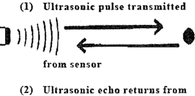
The working principle of an ultrasonic sensor is very simple. Basically it comes with two transducers. The first one is used for transmitting the signal and second one is used for receiving the signal. The transmitter will transmit the signal to the surrounding. This signal will be bounced back if it hit an object. The bounced echo signal is then picked up by the receiver which will give the signal to a set of amplifiers and finally converted to digital signal by means of comparator or other method. The output of the sensor which is in the form of particular value of voltage is heavily depends on the distance of an object detected.
(1) Ultrasonic pulse transmitted
)
}})))})
<ii-(---·
)
from sensor
(2) Ultrasonic echo .retu1·ns from target
2.3 PIC MICROCONTROLLER
A microcontroller is widely used by robot developer to build the processor of the robot. One of the common controllers used is PIC microcontroller produced by Microchip Technology. The controller processes the input capture by the ultrasonic sensor and produce output which control the robot navigation. The implementation of the PIC microcontroller is very practical since it is easy to program and reprogram.
The PIC16F84A belongs to the mid-range family of the PIC microcontroller devices which is commonly used for robotic project. The program memory contains IK words, which translates to I 024 instructions, since each 14-bit program memory word is the same width as each device instruction. The data memory (RAM) contains 68 bytes. Data EEPROM is 64 bytes. There are also 13 1/0 pins that are user-configured on a pin-to-pin basis. Some pins are multiplexed with other device functions. These functions include external interrupt, Change on PORTB interrupt and timerO clock input. [SJ
The PIC16F84A has a host of such features intended to maximize system reliability, minimize cost through elimination of external components, provide power saving operating modes and offer code protection. These features are:
• OSC Selection • Reset
-Power-on Reset (POR) -Power-up Timer (PWRT) - Oscillator Start-up Timer (OST) • Interrupts
• Watchdog Timer (WDT) • SLEEP
• Code protection • ID locations
RA2 +---+ +---+RAJ RA3 +---+ ... RAO RA4/TOCKI +---+ - OSC1/CLKIN lll::r:R __,.. __,.. OSC2/CLKOUT Vss __,.. -voo RBO/INT +---+ -RB7 RBI.._.. -RBB RB2 +---+ ...,.RB5 RB3 ..._.. ... RB4
Figure 3: PIC16F84A Pin Diagram
2.4 MOTOR CONTROLLER
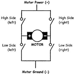
Motor controller for this mobile robot is actually an H-Bridge circuit. The H-bridge is so named because it has four switching elements at the "comers" of the H and the motor forms the cross bar. The basic bridge is shown in the figure below.
High Side (left) low Side {left) Motor Power ( +) Motor GrOUI'Id
H
Figure 4: H-Bridge Configuration
High Sid1! {right)
!,.ow Side
The key fact to note is that there are, in theory, four switching elements within the bridge. These four elements are often called, high side left, high side right, low side right, and low side left (when traversing in clockwise order).
The switches are turned on in pairs, either high left and lower right, or lower left and high right, but never both switches on the same "side" of the bridge. If both switches on one side of a bridge are turned on it creates a short circuit between the battery plus and battery minus terminals. This phenomenon is called shoot through in the Switch-Mode Power Supply (SMPS) literature.
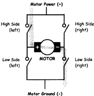
To power the motor, it is desired to turn on two switches that are diagonally opposed. In the picture below, it is shown if the high side left and low side right switches are turned on. The current flow is shown in green.
High Side (left) Low Side (left) Motor Ground (-) High Side (right) Low Side (right)
Figure 5: Current flow through H-Bridge Circuit
The current flows and the motor begins to turn in a "positive" direction. If the high side right and low side left switches is turned on then the current flows the other direction through the motor and the motor turns in the opposite direction.
2.5
POWER SUPPLYPower supply is essentially important for mobile robots that have such a complex systems which rely on software, hardware and mechanical systems all working together. In many large scale robots, the power of the robot will be supplied by rechargeable batteries. There are many types of batteries in the market that is suitable for robotics project purposes. The difference is with the material that is used for the batteries and also the value of current that the battery can supply for a particular period.
The type and design of the power supply itself is important to supply a specific voltage or current of the electronics circuits and the motor of the robot. This is to ensure that both circuits and motors run in a perfect behavior. Design of the power system is also important to ensure that power is distributed accordingly to all the circuits and most importantly to overcome electrical system noise issues.
3.1 PROCEDURE
CHAPTER3
METHODOLOGY
This obstacles avoidance mobile robot is mainly divided into two parts namely to build the hardware part and to develop the software part. Hardware design consists of mechanical structure, robot locomotion, mobile power supply, and sensor system. Software design is to develop the obstacles avoidance algorithm as the mobile robot method of navigation.
3.2 TOOL & EQUIPMENT
There are several hardware and software that were used throughout the project. These are the list of tools used:
HARDWARE
~ PIC16F84A
~ Ultrasonic Sensor
~ Battery
~ RC Platform
SOFTWARE
~ PCW
~ Warp 13
~ EAGLE
The obstacles avoidance algorithm which is to be implemented into the PIC16F84A is written compiled and debugged using PCW. This PCW software will actually produce a HEX file that is converted from the original program.
Warp 13 is the software used as a PIC Progranuner which uses the HEX file to be embedded into the PIC16F84A microcontroller. The PIC is programmed by using the Warp 13 board that can be connected to the PC via RS232 serial port.
Eagle is the software used for drawing the schematic diagram of the electronic circuits. Basically this software is used during the design process of constructing the electronic circuits.
3.3 PROJECT WORK
The project was separated into five major components which are shown in the figure below
Obstacles Avoidance
Mobile Robot
l
1
Structure PIC Microc-ontroller
I
Power Supp~I
I
SensorI
Motor Controller3.3.1 Structure
The structure of the robot is modified from a 4-wheel RC car which is stable and strong enough to withstand the load of new circuits and components. Minor adjustments need to be done to the body for adding on some new circuits and other components in order to ensure it is in perfect condition.
It is very important to have the basic structure or platform of the robot that is made from plastic-type materials with the intention that it can hold necessary load. For this matter, the original platform of the RC car itself is proved to be workable to hold the load which consists of some circuits and batteries other components. The shape of the robot is physically a rectangle. The advantage of using a four-sided figure platform is the movement of the vehicle is very limited. Thus, the method to control the navigation of the vehicle/mobile robot is much easier. Another thing is that the obstacles avoidance algorithm is much simpler to be developed.
The size of the platform is chosen to be within 150mm to 250mm in length and 140mm to 170mm in width. For a 4-wheel robot, the rear wheel is use to drive the robot in forward or reverse motion while the front wheel is used to steer the vehicle to the left or to the right. It is also important to have big tires so that it can run through a rough course.
3.3.2 Sensor
For the sensor unit part, ultrasonic type is chosen as the main input device for the robot to detect obstacle from the surrounding. The number of ultrasonic sensor to be used is two which are to be installed at the front right and front left of the mobile robot. It is known that ultrasonic sensors measure the distance or presence of a target by sensing a sound wave, above the range of hearing, at the object and then measuring the time for the sound echo to return. Knowing the speed of the sound, the sensor can determine the distance of the object from the transducer element.
One of the advantages of using an ultrasonic sensor is that it can provide a distance proportional output. This means that the sensor's outputs are proportional or related to the measured target range. The sensor ability to provide different value of output enables to perform proximity application where a mobile robot can determine the presence of objects to count or control their movement. The goal is to test the sensor and to find the appropriate value of output or target distance that is going to be used as an input for the PIC Microcontroller.
After getting the target distance or value of particular voltage output from the sensor, the next thing to do is to design voltage triggered circuit or basically a comparator. A comparator in this particular scope is fundamentally a device which compares two voltages and switches its output to indicate which is larger.
3.3.3 PIC Microcontroller
PIC 16F84A is chosen as the PIC for the microcontroller circuit. The PIC is an essential component as it acts as the brain of the robot. It processes the information received from the sensor which then control the robot navigation. It is this PIC that is going to be embedded with the obstacles avoidance algorithm program. The usage of PIC for the project is very suitable due to its low cost, wide availability, large user base, extensive collection of application notes, availability of low cost or free development tools, and capability of reprogramming.
Figure 8: PICI6F84A
The idea of using PIC is to design the microcontroller circuit which is capable to receive information from the ultrasonic sensor, processes the information and finally to transmit signal to the motor controller circuit. The design process includes some understanding of the PIC l6F84A and understanding of the functionality of every electronic components of the circuit.
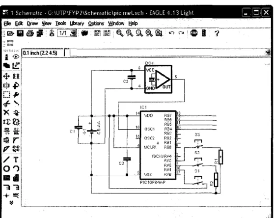
The schematic circuit of the microcontroller circuit is designed using EAGLE software. Figure below shows diagram of microcontroller circuit during designing process.
::::; 1 SchematiC G \UTP\FYP21Schemotic\plc mel.sch- EAGLE 4 13 L1ght 1_ 1
=
~Eife §jl Qraw ~ roars LibrarY Qptions ~indow ttefp
12--Iii ~
II 8
lttt
.ti
tl !l~H!-E ~ ~ §. ~ @I ._., ~--;-IDII ·;
-"""'"' ::":-..;
IL.1
14 \.·DO R97 D
F·r1~ 11
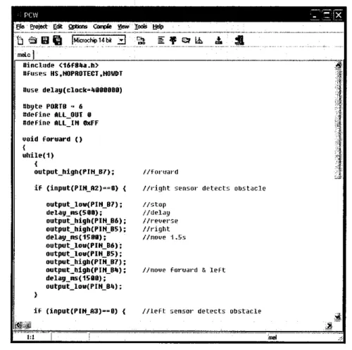
For the PIC part, PCW is the software used to write the obstacles avoidance algorithm program. The function of the obstacles avoidance algorithm is basically to drive the robot forwards until it detects an obstacle. Once it detects, it backs up, turns away from the side where the obstacle is detected, and resumes moving forward. Figure below shows some of the algorithm written using PCW.
~-~--gdit biliillli'! lt.ticrochip14bil 3 ~ ""''I #include <16F8-a.h> Dfuses HS.HOPROTECT.HOWDT ftuse delay(clock=4DOOOBO) Dbyte PORTO "' 6 #define All OUT 0 #define RLL=IH OXFF
uoid for~ard () { while(1) { output_high(PIH_B7); if (input(PIH_A2)~~B) { output_lou(PIH_B7); delag_ns(51JI); output_high(PIH_B6); output_high(PIH_B5); deolag_ms(15011); output_lou(PIH_B6); output_low(PIH_B5); output_high(PIH_B7); output_high(PIH_B4); delag_ms(15DO); output_lou(PIH_B4); if (input(PIH_A3)==0) { //fon1anl
//dght sensm· detects obstaclt> //stop
//llelay
/tf·evet"~e //t•ight //noiJe 1.5s
I /moue foruat·d & left
//left sensot· detects obstacle
Figure I 0: Writing Algorithm using PCW
til·
1
·.··.·.·~···
.. l···l ' ,j' ',-· ,liljj,-The program is then compiled into a HEX tile format which is then embedded into the PIC l6F84A microcontroller. The PIC is programmed by using the Warp 13 board that can be connected to the PC via RS232 serial port.
3.3.4 Motor Controller
For motor controller pmposes, H-Bridge circuit is used. This means that the navigation of the mobile robot from one point to another such as moving forward, reverse, moving right and left is totally being controlled by the H-Bridge circuit. Dual Full Bridge Driver (L298) is used for H-Bridge circuit purposes.
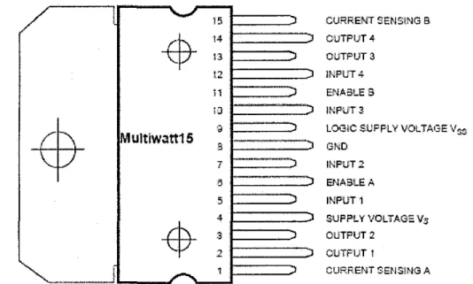
Basically for this particular part of the project is to understand the function and the pin configuration of the L298. This is to ensure that this device is compatible to be integrated between output pin of the PIC Microcontroller and both of the motors. Figure below shows the pin configuration of L298.
)5 CURRENT SENSiNG B
-$-
!4 OUTPUT 4-!3 OUTPUT3 L2 INPtJT 4 11-·----,
ENABLES lJ INPUT 3!Multiw.:ttt15 •• LOGIC SUFFLYVOLTAGE Vss
8 GND 7 INPUT 2 5 ENABLE A 5 INPUT l 4 SUFPL Y VOLTAGE Vs
-$-
3 OUTPUT 2 2 CUTFUT t CURRENT SENSlNGA3.3.5 Power Supply
The objective in designing a power supply is to provide a solution in order to supply robot's circuits and motors which are totally different in terms of power consumption or value of the current flow through it. It is important to understand all the circuits function in order to capture the idea that every detail such as power load, value of current and value of voltage are the key to provide a good power system design. This includes the target toward solving or avoiding noise problems of the robot.
The general design and construction of the mobile robot shall be made to receive power supply from a single source. For this case, the power supply will be from dry batteries.
It is to be expected that there would be unpredicted performance of the circuits and motors of the mobile robot when they are all running together. This is because circuits and motors consumed different amount of current. The unpredicted perfonnance can be seen as for example a control processor that crashes when the motors are turued on. It can also appear as sensors that are overly noisy, or a robot with just plain erratic behavior.
In this project, many circuits are being used to complete the robot. Basically, it is required that the electrons flow from a source, through a load, and then return to the source. Once current flow through a particular circuit, it produces different voltages at different points along it. This is because of the presence of resistance of each circuit. The right way to fix this problem is to isolate the power supply for every circuit and motors of the mobile robot. Figure 12 shows a typical power isolation scheme for a mobile robot.
CHAPTER4
RESULTS AND DISCUSSION
4.1 ROBOT STRUCTURE
4.1.1 Platform
Figure 13: Robot Platform
From the figure above, it can be seen that this 4-wheel platform is a stable vehicle and is reliable to be used as a self-navigating obstacles avoidance robot. The dimension of the robot platform is 200mm in length, 160mm in width and 70mm in height without an add on circuits or other components.
For the tires, it has the size of 60mm in diameter which is big enough to run through a rough terrain. The robot is a rear-wheel drive which means it uses rear tires to drive the robot in forward or reverse motion while the front tires is used for navigating to the left or right. The turning degrees of the front tires are I
oo
to the left and Ioo
to the right. As the turning degrees are quite small, the robot has to take quite a long distance in reverse motion when the robot detects an obstacle.The original board used as the main controller circuit has been removed and it is replaced with the H-Bridge and the PIC Microcontroller circuit. No other modification has been made to the platform as it is already reliable and stable for the use of this project.
4.1.2 Motor
Figure 14: Drive motor on the left and steer motor on the right
Original drive and steer motors from the RC Car are maintained and no modification has been made to both of it. Wires from both motors are directly connected to the H-Bridge circuit assembled on the strip board. Figure 15 below shows wiring connection of H-Bridge to both motors.
4.1.3 Power Supply
Figure 16: Motor and Circuits Power Supply
The original battery from the RC car is retained and is being used for driving both drive and steer motors and to supply power for the H-Bridge and the PIC microcontroller circuit. Each circuit is isolated by constructing all the circuits in parallel and connecting a capacitor at input and output pins of every circuit in order to eliminate the effects of noise to the circuits operation generated by the motors.
Table I: Circuits or Components Voltages
Circuits I Components Voltage
Sensor Circuit 12V, 4.8V & -4.8V
PIC Microcontroller Circuit 4.8V
4.2 CIRCUfTS
4.2.1 Sensor Circuit
Figure 17: Ultrasonic Sensor Circuit
Figure above shows the sensor circuit constructed on the breadboard. PIC 16F84A is used to generate 40 kHz square wave. LED is connected to the output of the circuit and the method to measure the output is by observing its brightness. A multimeter is used to measure the value of voltages produced by the output.
4.2.2 PIC Microcontroller Circuit
Figure 18: Microcontrolter Circuit on breadboard
Figure above shows the actual redesign circuit of the main controller circuit of the robot. PIC 16F84 is used as the main controller of the robot. It can be seen that there are two push buttons above the PIC. The buttons represent both left and right ultrasonic sensor of the robot. The main reason to use this button is to test and to ensure the reliability of the obstacles avoidance algorithm. LEDs are connected to the assigned output of the PIC to test the algorithm.
4.2.3 H-Bridge Circuit
An H-bridge is an electronic circuit which enables to drive both electric motors of the robot to be run. Basically L298 IC is used for this matter. Figure 20 shows the circuit which was constructed on strip board.
Figure 20: H-Bridge Circuit
4.3 PROGRAMS
The program written below is specifically designed for the algorithm created. Basically the algorithm drive the robot forward until it detects an obstacle; once it does, it backs up, turns away from the side where obstacle detected, and resumes moving forward. The program of the obstacles avoidance algorithm is written as below:
#include <16f84a.h>
#fuses HS,NOPROTECT,NOWDT #use delay( clock~4000000)
#byte PORTB ~ 6 #define ALL OUT 0 #define ALL IN OxFF
void forward () while( I)
}
{
output_ high(PIN _ 87); //forward
if (input(PIN _ A2f"~O) { //right sensor detects obstacle
}
output_low(PIN_87); //stop delay_ ms(500); //delay output_ high(PIN _ 86); //reverse output_ high(PIN _ 85); //right delay_ms(1500); //move 1.5s output_low(PIN _ 86);
output_low(PIN _ 85); output_ high(PIN _ 87);
output_high(PIN_84); //move forward & left delay_ ms(1500);
output_low(PIN _ 84 );
if(input(PIN_A3f"~O) { //left sensor detects obstacle output_low(PIN _87); //stop
delay_ms(500); //delay output_ hi gh(PIN _ 86 ); //reverse output_high(PIN_B4); //left delay_ms(1500); //move 1.5s output_low(PIN _B6);
output _low(PIN _ 84 ); output_ high(PIN _87);
output_high(PIN_85); //move forward & right delay_ ms(1500); output_low(PIN _ 85); } } main() { inti;
set_tris _ 8(ALL _OUT); set_tris_ A(ALL_IN); PORT8~0; do { i=O; if(input(PIN_Al)~~O) { forward(); } } while (TRUE); }
5.1 Conclusion
'CHAPTERS
CONCLUSION
The design to develop and construct a 4-wheel mobile robot with a PIC as its main controller is achieved. The PIC Microcontroller circuit works very well where it is able to receive information and manipulate the data in order to provide output for the motor controller circuit. The obstacles avoidance algorithm embedded into the PIC16F84A is also able to control the navigation of the robot. The motor controller circuit is able to receive input from PIC Microcontroller circuit and control the motors according to algorithm created.
The major problem faced is that the Ultrasonic Sensor Circuit was unable to provide consistent output that could be interpreted by the PIC Microcontroller circuit. One of the difficulties in utilizing this type of sensor is that to get a consistent output from the sensor. Steps have been taken in order to overcome this problem such as troubleshoot and replace each electronic component that might cause the problem but still the circuit works in an unpredictable manner.
5.2 Recommendations
Future works suggested that are to be done is basically to improve the robot performance in terms of its input medium, controller and physical settings. The recommendations or additional features suggested are briefly discussed below:
Structure
The existing structure is reliable for the purpose of moving from one place to another but it is a problem when the vehicle is stuck in a corner or a in a situation where the robot just not possible to move either forward or reverse. In this case, an almost circle shape of structure is more practical that a rectangle shape structure. It is recommended to add some pieces to make the existing structure to be more of circle shape.
Sensor
Presently, the mobile robot is using an ultrasonic sensor as its main input. One of the difficulties in utilizing this type of sensor is that to get a consistent output from the sensor. An alternative is to use another type of sensor such as Infrared sensor. This type of sensor provides beam pattern which is pretty consistent between types. The range is typically I 0-80 em and the beam is roughly football shaped with the widest portion in the middle being about 16 em wide. These detectors are a great addition to the suite of detectors available for robotics. They are quite inexpensive, use very little power, fit in small spaces, and have a unique range that is ideally suited to small robots. This sensor able to provide information whether a robot is close to a wall or far away is enough to make choices about what to do next.
Robot Controller
The existing obstacles avoidance algorithm is a very basic algorithm and using a PIC16F84A is sufficient to store low memory logical data. To develop a very complex algorithm, it is required to use bigger capacity PIC such as PIC16F87. This PIC contains more memory space, more input and output ports, and other special features. Many types of applications can be done using this PIC.
REFERENCES
[I] Mobile Robot
http://en.wikipedia.org/wiki/Mobile robot [2] PIC Microcontroller http:/ /en.wikipedia.org/wiki/PIC _ microcontroller [3] H-Bridge http://en.wikipedia.org/wiki/H-bridge [4] H-Bridge
http:/ I en. wikipedia.org/wiki!Motor _ controller#H -bridge
[5] PIC
http://melabs.picbasic.com/devicedata/35007a.pdf