an author's https://oatao.univ-toulouse.fr/25226
https://doi.org/10.2514/6.2019-2615
Jo, Yeongmin and Jardin, Thierry and Gojon, Romain and Jacob, Marc C. and Moschetta, Jean-Marc Prediction of Noise from Low Reynolds Number Rotors with Different Number of Blades using a Non-Linear Vortex Lattice Method. (2019) In: 25th AIAA/CEAS Aeroacoustics Conference (Aeroacoustics 2019), 20 May 2019 - 23 May 2019 (Delft, Netherlands).
Prediction of Noise from Low Reynolds Number
Rotors with Different Number of Blades using a
Non-Linear Vortex Lattice Method
Yeongmin Jo1∗, Thierry Jardin2, Romain Gojon3, Marc C. Jacob4, and Jean-Marc Moschetta5
ISAE-SUPAERO, Université de Toulouse, France
The demand of micro air vehicles (MAV) with multiple rotors is increasing in both military and civil applications because of their versatility on various missions. Howe-ver, the use of MAVs for some missions still has limited success because of their noise pollution. One of the main noise sources is aeroacoustic sound produced by the low Reynolds number flows around the rotors. There have been many previous studies about small-scale rotor systems of MAVs during the past decades, but they mainly fo-cused on investigations of the aerodynamics rather than the acoustics. Several studies considering the acoustics have started recently. However, only steady loading forces computed by using Blade Element Momentum Theory (BEMT) were considered in the previous studies, and the noise from unsteady flow phenomena were not taken into account. The main objective of the current study is to investigate the noise mecha-nisms and further to find ways to reduce the noise levels in unsteady low Reynolds number flows. A Non-linear Vortex Lattice Method (NVLM) is used to simulate the unsteady low Reynolds number flow and model the corresponding noise sources. The tonal components of far-field noise is predicted by using an acoustic analogy based on Ffowcs Williams-Hawkings (FW-H) equations. These numerical methods are applied to low Reynolds number propeller and rotor cases, and validated upon experimental data. Then, they are used to investigate the influence of the number of blades on both aerodynamic and aeroacoustic performance and provide further insight into prominent sources of noise.
I. Introduction
The demand of micro air vehicle (MAV) is increasing in both military and civil applications. Especially, the MAV with multiple rotors is widely used for various missions thanks to its good hovering and stability performance as well as its high controllability. Despite of their high versatility, MAVs are not yet fully deployed in some missions because of the noise pollution they produce. This is the case for military reconnaissance missions and for civil use in populated areas. This is one of the reasons why drone delivery is not yet widely spread.
The aerodynamic phenomena occurring around small-scale rotors are completely different from that of large rotorcraft such as helicopters. Because of the small-scale and the relatively slow flight speed, low Reynolds number flows ranging from Re = 104 to 105 typically occur. In this range,
1. Postdoctoral Associate, Département Aérodynamique, Énergétique et Propulsion (DAEP), AIAA member, yeongmin.jo@isae-supaero.fr
2. Research Associate, Département Aérodynamique, Énergétique et Propulsion (DAEP), AIAA member, thierry.jardin@isae-supaero.fr
3. Research Associate, Département Aérodynamique, Énergétique et Propulsion (DAEP), AIAA member, romain.gojon@isae-supaero.fr
4. Professor, Département Aérodynamique, Énergétique et Propulsion (DAEP), AIAA senior member, marc.jacob@isae-supaero.fr
5. Professor, Département Aérodynamique, Énergétique et Propulsion (DAEP), AIAA senior member, jean-marc.moschetta@isae-supaero.fr
25th AIAA/CEAS Aeroacoustics Conference 20-23 May 2019, Delft, The Netherlands
10.2514/6.2019-2615 Aeroacoustics Conferences
the viscous forces dominate the fluid momentum in a large part of the blade boundary layers, so that the flow easily separates from the blade surface and does not re-attach. As a result, the aerodynamic performance is significantly impacted. Moreover, for such low Reynolds number flows, noise generation mechanisms are different from the one observed for high Reynolds number flows encountered on large rotors.
During past decades, MAVs have been studied in several studies in terms of aerodynamics, control and stability, and structural dynamics. Kunz [1] used a low-fidelity numerical analysis of Blade Element Momentum Theory (BEMT) and also adopted experiments to design aerodynami-cally efficient rotor shapes for a MAV. A structural deformation of the rotors was also considered and a meso-scale MAV system named ’Mesicopter’ was developed. Bohorques, in Ref. [2], investigated the aerodynamic phenomena arising in small-scale rotors by combining BEMT and an experimental approach. He further suggested an optimal sectional airfoil and planform shapes to achieve higher aerodynamic performance. However, studies focusing on the aeroacoustics of small-scale rotors have started only recently. Zawodny et al. [3] investigated numerically and experimentally the aeroa-coustic of a MAV rotor. For the aerodynamic fields, experimental data were used to validate a low-fidelity approach based on BEMT and a high fidelity one consisting in performing a Detached Eddy Simulation. For the radiated acoustic, they used both an acoustic analogy based on Ffowcs Williams-Hawkings (FW-H) equations and a semi-empirical model for tonal and broadband noise. They compared their results with experimental data. Nana et al. [4] and later Serré et al. [5] perfor-med the design optimization of a rotor with the objective to improve the aerodynamic performance and to minimize the noise level using BEMT. The FW-H equations and a statistical broadband noise model based on linearized unsteady aerodynamic airfoil theory were used. The optimization result was validated by experiments detailed in the paper of Serré et al., and further detailed analysis for the aerodynamics and acoustics were published by the authors in another paper [6].
In these previous studies, BEMT was commonly used because of its efficiency and capabilities in performing simulations of low Reynolds number flows. Although BEMT computes a steady loading solution, a tonal noise signal can be obtained with BEMT because of the relative accelerated motion between the rotating blades and the observer locations. However, unsteady loading forces may also induce large amount of tonal noise and are likely to level out steady loading noise at the low Mach numbers of MAV rotors. Tones at multiples of the Blade Passing Frequency (BPF) due to unsteady loading appear whenever the rotor blades cross a steady flow distortion (which appears periodic in the blade frame of reference). These can be due to a mast / strut, a stator, a casing element or simply to ingested large scale turbulent structures which do not need to be very intense (residual turbulence in a medium "at rest" can be the cause of powerful tones). Therefore, an efficient unsteady aerodynamic flow solver is essential for more accurate design results.
Detached Eddy Simulation or Large Eddy Simulations can be used for this purpose, but those methods are computationally very expensive and cannot be coupled with in a design optimization process for example.
Conventional Vortex Lattice Method (VLM) is widely used to simulate unsteady flows for ro-torcraft such as helicopters. It is a Boundary Element Method (BEM) and requires only surface elements not volumic elements to compute a flow solution. It solves the linear potential flow go-verned by Laplace’s equation using analytic Green’s functions. However, the governing equation is derived assuming an inviscid non-viscous flow. Thus, the conventional VLM is inapplicable to low Reynolds number flows. In order to overcome this problem, a Non-linear VLM (NVLM) was developed in the author’s previous study [7]. NVLM includes the viscous flow effects indirectly into a flow solution by using a "look-up table" with viscous flow data for the sectional airfoil. During the iterative computation, NVLM substitutes an equivalent solution found by the table look-up method for the linear solution, following an approach that will be described in the following section. Thus, NVLM can be used to efficiently simulate unsteady low Reynolds number flows. Hereafter, it will be used to compute unsteadiness developing on the blade surfaces and feeding their wakes. Please note that it can also be applied to model incoming disturbances and flow distortions.
The main objective of the current study is to develop a method to estimate the noise radiated by MAVs that is both fast and representative enough to be integrated into an aeroacoustic optimization tool. This will open the road to reduce the noise generated by unsteady low Reynolds number flows. For that, NVLM is used as a flow solver, and the unsteady loading on the blade is used to derived the far field acoustic using both the monopole and the dipole term of the FW-H equation.
This paper is organized as follows. First, the numerical approaches undertaken are introduced and their implementation is discussed in Sec. II. Then, they are validated in two rotor cases in Sec. III. A parametric study on the number of blade of the rotor is finally carried out, and the results are discussed in Sec.IV. Main conclusions are summarized in section Sec.V.
II. Numerical Methods
In this section, the numerical approaches used for aerodynamics and acoustics are introduced. First, NVLM and its application to unsteady low Reynolds number flows is briefly described. Then acoustic analogies for loading and thickness noise from NVLM outputs are addressed.
A. Nonlinear Vortex Lattice Method
The nonlinear vortex lattice method used in this work is based on early works by [7]. The blade surface is discretized into two-dimensional panels on which Laplace equation for the velocity potentialφis solved :
∇2φ=φxx+φyy+φzz = 0 (1)
Remind that the above equation is derived from the Navier-Stokes equations with the assump-tions of inviscid, incompressible, and irrotational flows. Closing the system with non-penetration condition at the blade surface and Kutta condition at the trailing edge yields elementary solutions at each panel, in the form of line vortices with circulationΓ. The resulting circulation distribution at each spanwise cross-section is obtained, hence a lift force following Kutta-Joukowski theorem.
The solution is linear and therefore shows limitations at low Reynolds numbers. Nonlinearity is thus introduced using a table look-up procedure. That is, the circulation distribution obtained from linear solution at each cross section is offseted such that the sectional lift matches that obtained on two-dimensional airfoils at similar operating conditions using approaches accounting for non-linearities. Data obtained from these approaches (e.g. from experiments or from resolution of the Navier-Stokes equations) are stacked in tables and passed to the NVLM code.
Note that defining the conditions at which each cross-section operates is not straightforward. That is, the induced velocity resulting from lift production is computed at each panel with Laplace equation, whereas a unique value representative of the flow over the whole cross-section is required to define the effective angle-of-attack, hence lift from table look-up procedure. In the previous work by [7], it was suggested to define a reference control point where the induced velocity from Laplace equation is representative of the overall induced velocity over that airfoil. This point location was found via asymptotic analysis for a two-dimensional flat plate and a cambered airfoil, and it is located at the center of the chord on the mean camber line of the airfoil.
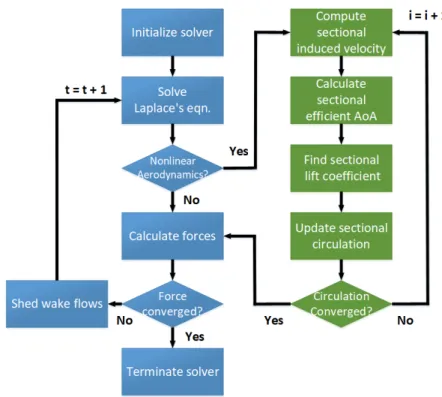
Because induced velocity depends on lift and circulation distributions, which in turn depend on induced velocity, the procedure is iterative. In addition, when the solver is advancing in time, vortices in the rearmost panel are shed into the wake at each time step and the whole procedure (Laplace equation and iterative table look-up procedure) is performed again for the next time step. The algorithm is shown in figure1. Further details on the numerical procedure can be found in Ref. [7].
The NVLM code is developed in Python language to easily integrate it into previously developed design optimization framework for rotors [5]. In order to speed up the code, the most expensive rou-tines were implemented in Cython. Here, NVLM incorporates a vortex particle method to model the wake flows. Hence, computation which has to account for influences between the particles generates O(N2
p)cost, where the number of particlesNpsteadily increases during the computation along with the wake growth. As a result, NVLM tackles a N-body problem and dominates the computation time. This type of problem can be solved using popular acceleration schemes like the fast multipole method (FMM). A classical FMM with tree-code structures can reduce the computation costs from O(N2
p) down to O(Np), thus allowing to significantly speed-up the computation. In the current study, an open-source library of kernel-independent FMM of KIFMM3D code [8] is integrated into the NVLM code. Finally, the overall code structure is parallelized through message passing interface (MPI).
Figure1 Computation procedure of NVLM
B. Acoustic Analogy for Far-Field Noise
In the current study, the FW-H equation is used to predict the far-field noise. In its general form, it has three source terms : monopole, dipole, and quadrupole. Since NVLM is a boundary element method, it only takes into account the surface integrals (monopoles and dipoles), the volume terms (quadrupoles) being ignored. This approximation is justified for low Mach number applications to which MAV definitely belong. Farassat-1A formulation described in Ref. [9] is an implementation of the FW-H equation adapted to our solver. Indeed, it is restricted to the loading and thickness terms which correspond to the dipole and monopole terms. The Integral form of each term is expressed as follows : 4πp0L = 1 c Z f=0 l˙ r r|1−Mr|2 ret dS+ Z f=0 l r−lM r|1−Mr|2 ret dS+1 c Z f=0 l r(rM˙r+cMr−cM2) r2|1−M r|3 ret dS (2) 4πp0 T = 1 c Z f=0 ρ 0( ˙vn+vn˙) r|1−Mr|2 ret dS+ Z f=0 ρ 0vn(rM˙r+cMr−cM2) r2|1−M r|3 ret dS (3)
where the subscripts ’L’ and ’T’ represent the loading and thickness noise terms, respectively. In each term, the point above the variables represents a time-derivative regarding to the retarded (’ret’) or observer time, the subscriptsr,M, ornrepresent a dot product between the subscripted variable and the corresponding variable. For example,lrrepresents the dot product between~land~rwhere~l is a surface force vector at the noise source andris a radiation direction vector from a noise source to an observer, respectively.M is the Mach number,vn is the normal velocity of a noise source,ρ0
is the free-stream density, andc is the speed of sound, respectively.
The flow properties on the blade surfaces in Eq.2have to be obtained to compute the loading noise, and they are computed by using NVLM. For the thickness noise, surface panels corresponding to the blade lattices for NVLM are generated, and the necessary variables in Eq. 3 are computed using the surface panels and their rotating motion. Finally, the solution for the far field noisep0T onal is expressed as the sum of of the two terms as follows :
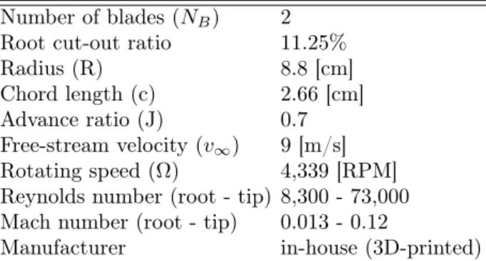
Table 1 Propeller geometry and operating conditions (test case 1)
Number of blades (NB) 2 Root cut-out ratio 11.25% Radius (R) 8.8 [cm] Chord length (c) 2.66 [cm] Advance ratio (J) 0.7 Free-stream velocity (v∞) 9 [m/s] Rotating speed (Ω) 4,339 [RPM] Reynolds number (root - tip) 8,300 - 73,000 Mach number (root - tip) 0.013 - 0.12
Manufacturer in-house (3D-printed)
Table 2 Rotor geometry and operating conditions (test case 2)
Number of blades (NB) 2 Root cut-out ratio 7 % Radius (R) 12 [cm] Chord length (c) varying Advance ratio (J) 0 Free-stream velocity (v∞) 0 [m/s] Rotating speed (Ω) 5,400 [RPM] Reynolds number (root - tip) 3,000 - 70,000 Mach number (root - tip) 0.01 - 0.2 Manufacturer DJI
p0T onal(~x, t) =p0L(~x, t) +p0T(~x, t) (4)
III. Validation of the Solver
Numerical methods for aerodynamics and acoustics described in Sec. II are validated against two experimental cases.
The first test case is reported in Ref. [10]. It consists of a two-bladed propeller operated in axial flight condition with an advance ratio J = v∞/ΩR = 0.7, where v∞, Ω and R are the freestream velocity, the propeller rotation speed and the propeller radius, respectively. The 3D-printed blades have NACA0012 airfoil sections with constant chord and variable twist determined byβ =tan−1C
r whereCis a variable based upon the tip twist angle asC=tan20
o,ris the fractional radius. Propeller geometry and operating conditions are summarized in table 1. This test case is used to validate NVLM against in-house aerodynamic data (i.e. aerodynamic thrust and torque). Aerodynamic polars computed with Xfoil [11] are used as inputs for the look-table procedure. Xfoil has proven to be accurate for low Reynolds number, attached flows [12] corresponding to those at which the present propeller operates (the present propeller has been designed to ensures low effective, sectional angle of attack atJ = 0.7).
The second test case is reported in Ref. [3]. It consists of a two-bladed rotor operated in hovering flight condition, i.e. v∞ = 0. The geometry of this commercial rotor was obtained in Ref. [7]. It is summarized in in table2, together with operating conditions. This test case is used to validate both NVLM and FW-H against aerodynamic and acoustic data (i.e. aerodynamic thrust and torque and far-field noise spectrum). Aerodynamic polars computed with the Stanford University Unstructured (SU2) flow solver [13] are used as input for the look-table procedure. The latter employs a finite-volume approach to solve the Reynolds-Averaged Navier-Stokes, RANS) equations. The Sparlart-Allmaras (SA) turbulence model and the Bas-Cakmakciouglu (BC) transition model are used with typicaly+ values below 1.
Table 3 Influence of spatial resolution on thrust and torque Grid cells along chord cells along span CT (%error) CQ (% error) 1 5 10 0.00932 (0.14) 0.00108 (0.73) 2 11 20 0.00931 (0.09) 0.00109 (0.04) 3 15 30 0.00931 (0.04) 0.00109 (0.00)
Table4 Influence of temporal resolution on thrust and torque
Time rotor rotation CT (% error) CQ (%error) 1 10◦ 0.00927 (0.15) 0.00108 (3.19) 2 5◦ 0.00931 (0.24) 0.00109 (2.64) 3 2.5◦ 0.00928 (0.02) 0.00109 (2.51)
A. Convergence with respect to spatial resolution
Convergence with respect to spatial resolution is first assessed on the rotor case at 5,400 RPM. Three different surface grids with resolutions5×10,11×20and15×30are tested. The time step corresponds to a5◦ rotor rotation and computations are run for 30 rotations to ensure that initial transients have sufficiently decayed. Mean thrust and torque coefficients reported in table 3 are obtained by time-averaging instantaneous thrust and torque signals over 10 rotations (i.e. from 20 to 30 rotation periods), respectively, and non-dimensionalizing with respect to rotor radius R and rotation speedΩ, CT =T /ρπΩ2R4 and CQ=Q/ρπΩ2R5. Their relative error with respect to the Richardson extrapolated solution demonstrates convergence and changes inCT andCQ values with spatial resolution are negligible in this case (i.e. below1%).
Fig. 2 and Fig.3 show the mean pressure value (p¯) and the root mean-squared (RMS) value of the pressure fluctuation (p0 =p−p¯) on the blade surface, respectively. Again, statistical values are obtained from 20 to 30 rotation periods. Overall, it is shown that spanwise locations of maxima in p¯andp0 predicted by Grid 2 and 3 are shifted inboard with respect to that obtained with Grid 1. These maxima can be correlated with the interaction between the blade and the wake from the preceding blade, a phenomenon that is expected to be a prominent source of noise radiation.
Specifically, pressure fluctuationp0 is modeled as noise source for the far-field noise prediction. The influence of spatial resolution on far-field noise prediction is plotted on Fig.4, in terms of sound pressure level (SPL) spectra, for an observer located 1.905 m away from the rotor center and 45o below the rotating plane, consistent with the experimental setup reported in Ref. [3]. As expected from Fig.3, Grid 1 case shows over-predicted levels in the overall frequency range, whereas results from Grid 2 and Grid 3 cases show relatively similar levels. Yet, all spatial resolutions provide similar predictions for tonal noise at the BPF.
B. Convergence with respect to temporal resolution
The similar rotor case at 5,400 RPM is used to assess convergence with respect to temporal resolution. The finest spatial resolution15×30is used with three different time steps corresponding to2.5◦,5◦ and10◦ rotor rotation per time step. Mean thrust and torque coefficients obtained with different time steps are reported in table 4, together with their relative error with respect to the Richardson extrapolated solution. Again, convergence is demonstrated for bothCT andCQ.
(a) Grid 1 : 5 x 10 (b) Grid 2 : 11 x 20 (c) Grid 3 : 15 x 30
(a) Grid 1 : 5 x 10 (b) Grid 2 : 11 x 20 (c) Grid 3 : 15 x 30
Figure 3 RMS value of pressure loading [Pa] on the blade surface for different spatial
reso-lutions.
Figure4 SPL spectra for different grid resolutions.
Fig.5and Fig.6show mean and RMS pressure contours on the blade surface, respectively. Here, all cases predict similar locations in p¯andp0 maxima and in the overallp¯distributions. However, distribution in RMS values for Time 1 case significantly differs from that obtained for Time 2 and Time 3 cases. Accordingly, discrepancies between solutions by Time 1 case and Tim 2 and Time 3 cases are observed on far-field noise spectra shown in Fig.7. In particular, Time 1 case over-predicts SPL over the whole frequency range in comparison to Time 2 and Time 3 cases, including tonal noise at the BPF. Although not shown here for the sake of conciseness, it can be shown that low spatial and temporal resolutions result in discrete flow features associated with large pressure gradients which are in part responsible for overprediciton in SPL.
C. Comparison against experiments
Based on previous conclusions, both propeller and rotor cases are computed with spatial reso-lution 15×30 (Grid 3) and temporal resolution corresponding to 5◦ rotation per time step (Time 2).
Mean thrust and torque coefficients obtained on the propeller case are reported in table5along with experimental values provided in Ref. [10]. Discrepancies between NVLM and experiments are shown in brackets. Remind that operating conditions for this test case are summarized in table1.
(a) Time 1 :10◦ (b) Time 2 :5◦ (c) Time 3 :2.5◦
(a) Time 1 :10◦ (b) Time 2 :5◦ (c) Time 3 :2.5◦
Figure 6 RMS value of pressure loading [Pa] on the blade surface for different temporal
resolutions.
Figure7 SPL spectra for different temporal resolutions
Mean thrust coefficient obtained on the rotor case are reported in table6along with experimental and DES data provided in Ref. [3]. Discrepancies between numerical methods (present NVLM and DES by [3]) and experiments are shown in brackets. Operating conditions for this test case are summarized in table2.
Overall, it is shown that NVLM predicts thrust within 6% of experimental values. This level of accuracy is in line with previous works on low Reynolds number rotors [14–16]. Note that results obtained from NVLM depend on aerodynamic polars used as input for the look-up table procedure. Using polars from Xfoil is of significant practical interest as it allows fast computation over a wide range of angles of attack and Reynolds numbers. Yet, NVLM simulations for the propeller case were also performed using experimental polars by Ref. [17] and resulted in similar levels of accuracy, i.e. within 6% of experimental values for both thrust and torque.
SPL obtained for the rotor case, at a point observer located 1.905 m away from the rotor center and 45o below the rotating plane, are plotted on figure 8. Levels from both steady (i.e. propagatingp¯) and unsteady (i.e. propagatingp¯+p0) sources are depicted to highlight the influence of unsteady approaches in recovering the overall SPL. In that regard, NVLM results are compared with experiments and DES from Ref. [3], which include unsteady sources, and BEMT from Ref. [3], which only accounts for steady sources.
Overall, it is observed that all methods provide reasonable prediction for tonal noise at the BPF. Specifically, experiments, DES, BEMT and NVLM steady and unsteady sources result in 45.803, 45.200, 45.200, 43.970, 44.786 dB respectively. On the other hand, tonal noise at the second harmonic
Table 5 Comparison between present results and experiments by [10] for the propeller case
Methods CT (% error) CQ (%error) NVLM 0.114 (5.96) 0.0196 (2.00) Experiments [10] 0.107 0.0199
Table 6 Comparison between present results and experiments and DES by [3] for the rotor case (5,400 RPM) Methods CT (%error) NVLM 0.00931 (0.45) DES [3] 0.00899 (2.99) Experiments [3] 0.00927 Figure8 SPL spectra (5,400 RPM).
is underpredicted by BEMT and NVLM approaches. Interestingly, it is observed that unsteady sources in NVLM have non-negligible contributions to tonal noise and significant contributions to broadband noise. Note that the SPL obtained from experiments include noise radiated by motor loading (only unloaded motor noise was extracted from measurements in Ref. [3]) and installation effects due to the experimental setup.
IV. Influence of the Number of Blades
In this section, a parameter study is carried out to investigate the influence of the number of blade on far-field noise radiation. A rotor with constant chord and constant pitch NACA0012 blade sections is considered and the number of blades is varied from 1 to 4. NVLM computations are performed at a given thrust of 2.945 N. Determination of rotor rotation speed to achieve the target thrust requires a trial-and-error iterative process which may significantly increase computational cost depending on the precision within which one wants to achieve the target value. Here, target thrust are achieved within approximately 2%. Rotor geometry and operating conditions are summarized in table7. Based on previous validation tests, Xfoil polars are here used as inputs for the table look-up procedure.
Figure 9 displays the thrust coefficient-to-solidity ratio and figure of merit obtained for the four cases. Again, statistics are obtained over 10 rotations once initial transients have sufficiently decayed. Because the rotation speed decreases with the number of blades to achieve the target thrust value, it is straightforward that the overall CT decreases with N. CT/σ is therefore more relevant in assessing aerodynamic thrust performance. It can be seen that CT/σdecreases withN, which presumably results from enhanced blade-wake interactions and, to a minor extent, Reynolds number effects (Reynolds number decreases with N). Conversely, the figure of merit exhibits an optimum value forN= 3. This trend results from competing mechanisms associated with Reynolds number effects, blade-vortex interactions and reduced blade loading. Note however that the gain in F M fromN = 2 toN = 3 is within the numerical error highlighted in sectionIIIand within the accuracy to which target thrust is achieved.
Table 7 Rotor geometry and operating conditions
Segment Value
Number of blades (NB) 1, 2, 3, 4 Root cut-out ratio 15% Radius (R) 12.5 [cm] Chord length (c) 2.5 [cm] Advance ratio (J) 0 Free-stream velocity (v∞) 0 [m/s]
Rotating speed (Ω) 7,600, 6,000, 5,300, 4,950 [RPM] Reynolds number (root - tip) 10,000 - 130,000
Mach number (root - tip) 0.02 - 0.23
Figure9 Thrust coefficient-to-solidity ratio and figure of merit for different number of blades.
Figure 10 displays the corresponding SPL obtained from both steady and unsteady loading sources. It is clear that SPL obtained from steady loading sources is significantly reduced as the number of blades increases, due to the lower rotation speed needed to achieve the given target thrust. In particular, tonal noise at the BPF is reduced from nearly 71.398 dB forN= 1to approximately 20.303 dB forN = 4. This reduction in SPL is mitigated by unsteady sources which add broadband noise over the whole spectrum, although SPL at the BPF is not increased much as the maximum increase is 3 dB forN = 3. Hence SPL curves roughly collapse at frequencies above 1 kHz, except for theN = 1case which exhibits lower SPL.
That is, figure10reveals two competing mechanisms associated with lower rotation speed (tonal noise) and enhanced blade-vortex interactions (broadband noise) with increasing number of blades. Figure11displays the total SPL, i.e. including thickness noise. It is observed that the thickness noise increases or decreases the tonal noise at the BPF depending on the phase difference between the unsteady loading and thickness noise signals, which are approximately -0.23 dB forN = 1 and 6.56 dB forN = 4. However, that over 1 KHz does not change as the thickness noise only contributes to the tonal noise.
The influence of the number of blades on aerodynamic performance and aeroacoustic footprint is summarized in terms of dimensional values on table 8. Percentage differences with respect to the N = 1 case are shown in brackets for cases with N = 2, 3 and 4. Overall, it is shown that aerodynamic efficiency is maximized for N = 3, whereas noise radiation monotonically decreases withN. Therefore, there exists a trade-off between aerodynamic efficiency and acoustic stealth. Yet, three-bladed rotors offer an interesting alternative solution to more commonly used two-bladed as they tend to enhance both aerodynamic and aeroacoustic performance. Note however that this does not take into account the weight increment due to additional blades.
(a) SPL Spectra using steady loading sources (b) SPL Spectra using unsteady loading sources
Figure10 SPL spectra using steady and unsteady loading sources.
Figure11 SPL spectra for total noise.
V. Conclusion
In this study, the aeroacoustic noise produced by low Reynolds number propellers and rotors typical of MAVs was investigated. This was achieved using numerical simulations based on NVLM and the acoustic analogy as modeled by the FW-H equations.
The numerical methods were first validated against low Reynolds number rotor and propeller experimental cases. It was shown that NVLM predicts both thrust and torque for both propeller and rotor cases with reasonable accuracy, i.e. within the error commonly reported for higher fidelity methods. In addition, using noise sources from NVLM, the acoustic analogy was found to provide reasonable estimates for tonal noise at the BPF. However, discrepancies at BPF harmonics and
Table8 Comparison of Thrust, FM, and OASPL
1 blade 2 blades (% diff.) 3 blades (% diff.) 4 blades (% diff.) Thrust [N] 2.950 2.945 (-0.170) 2.897 (-1.785) 2.892 (-1.948) Power Loading (PL) [s/m] 0.093 0.098 (+5.736) 0.099 (+6.827) 0.096 (+4.181) OASPL [dB] 73.421 59.537 (-18.910) 45.478 (-38.059) 32.032 (-56.372)
for broadband noise were observed, although comparing broadband noise with experimental data can not be thoroughly conducted due to additional sources of noise in the experiments (e.g. loaded motor noise). Considerations on spatial and temporal convergence of the present methods were also provided.
The methods were then used to assess the influence of number of blades on both aerodynamic and aeroacoustic performance of rotors. Rotors with 1, 2, 3 and 4 blades were investigated at a given thrust value. The target thrust was obtained with a trial-and-error procedure and achieved with approximately 2% accuracy. Because the target thrust was equal for all cases, the rotation speed decreased with the number of blades. First, it was found that aerodynamic efficiency is maximized forN = 3. This trend is believed to arise from competing mechanisms associated with blade-wake interactions, blade loading and, to a minor extent, Reynolds number effects. Second, although rela-tively straightforward, tonal noise decreases significantly with number of blades (because rotation speed decreases). Conversely, broadband noise increases due to enhanced blade-wake interactions. Despite these two competing mechanisms, the overall sound pressure levels were found to monoto-nically decrease with the number of blades. Consequently, because aerodynamic and aeroacoustic performance do not follow similar trends, there exists a trade-off between aerodynamic and acoustic constraints.
Future work will consist in experimental measurements of the present numerical study and in further analysis of noise sources from blade-wake interactions at low Reynolds numbers.
Acknowledgment
This research is supported by ’Micro-Drone Furtif 7’ program through Direction Générale de l’Armement (DGA) from the French Ministry of Defense.
References
[1] Kunz, P. J., “Aerodynamics and Design for Ultra-Low Reynolds Number Flight,” Ph.D. Dissertation, Stanford University, 2003.
[2] Bohorquez, F., “Rotor Hover Performance and System Design of An Efficient Coaxial Rotary Wing Micro Air Vehicle,” Ph.D. Dissertation, University of Maryland, College Park, 2007.
[3] Zawodny, N. S., Boyd, D. D., and Burley, L. C., “Acoustic Characterization and Prediction of Re-presentative Small-Scale Rotary-Wing Unmanned Aircraft System Components,” American Helicopter Society 72nd Annual Forum Proceedings, Palm Beach, FL, U.S.A., 2016.
[4] Nana, C., Moschetta, J.-M., Bénard, E., Prothin, S., and Jardin, T., “Experimental and Numerical Ana-lysis of Quiet MAV Rotors,” 50th 3AR International Conference on Applied Aerodynamics, Toulouse, France, 2015.
[5] Serré, R., Chapin, V., Moschetta, J. M., and Foumier, H., “Reducing the Noise of Micro-Air Vehicles in Hover,” International Micro Air Vehicle Conference and Flight Competition (IMAV) 2017, Toulouse, France, 2017.
[6] Serré, R., Gourdain, N., Jardin, T., Lopez, A. S., Balaramraja, V. S., Belliot, S., Jacob, M. C., and Moschetta, J.-M., “Aerodynamic and Acoutsic Analysis of An Optimized Low Reynolds Number Flow,” International Symposium on Transport Phenomena and Dynamics of Rotating Machinery (ISROMAC) 2017, Maui, Hawaii, U.S.A., 2017.
[7] Jo, Y., Lee, H., and Lee, D. J., “Prediction of Rotor Flow for Unmanned Aerial System Using Nonlinear Vortex Lattice Method,” 6th Asia/Australian Rotorcraft Forum / Heli Japan 2017, Kanazawa, Japan, 2017.
[8] Ying, L., Biros, G., and Zorin, D., “A Kernel-independent Adaptive Fast Multipole Method in Two and Three Dimensions,” Journal of Computational Physics, Vol. 196, No. 2, 2004, pp. 591–626.
[9] Brentner, K. S. and Farassat, F., “Modeling Aerodynamically Generated Sound of Helicopter Rotors,” Progress in Aerospace Sciences, Vol. 39, No. 2, 2003, pp. 83–120.
[10] Leng, Y., Jardin, T., Bronz, M., and Moschetta, J.-M., “Experimental Analysis of Propeller Forces and Moments at High Angle of Incidence,” AIAA Scitech 2019 Forum, Orlando, FL, U.S.A., 2019. [11] Drela, M., “XFOIL : An Analysis and Design System for Low Reynolds Number Airfoils,” Low reynolds
number aerodynamics, 1989.
[12] Morgado, J., Vizinho, R., Silvestre, M. A. R., and Páscoa, J. C., “Xfoil vs CFD Performance Predictions for High Lift Low Reynolds Number Airfoils,” Aerospace Science and Technology, Vol. 52, 2016, pp. 207– 214.
[13] Palacios, F., Colonno, M. R., Aranake, A. C., Campos, A., Copeland, S. R., Economon, T. D., Lonkar, A. K., Kukaczyk, T. W., Taylor, T. W. R., and Alonso, J. J., “Stanford University Unstructured (SU2) :
An open-source integrated computational environment for multi-physic simulation and design,” 51th AIAA Aerospace Sciences Meeting and Exhibit, Grapevine, Texas, 2013.
[14] Lakshminaraya, V. K. and Baeder, J. D., “Computational Investigation of Microscale Coaxial-Rotor Aerodynamics in Hover,” Journal of Aircraft, Vol. 47, No. 3, 2010, pp. 940–955.
[15] Jardin, T., Doué, N., Prothin, S., and Moschetta, J.-M., “Numerical Analysis of Pitching-Rotor Aero-dynamics,” Journal of Fluids and Structures, Vol. 62, 2016, pp. 175–186.
[16] Gourdain, N., Jardin, T., Serré, R., Prothin, S., and Moschetta, J.-M., “Application of a lattice Boltz-mann method to some challenges related to micro-air vehicles,” International Journal of Micro Air Vehicles, Vol. 10, No. 3, 2018, pp. 285–299.
[17] Ohtake, T., Nakae, Y., and Motohasi, T., “Nonlinearity of the Aerodynamic Characteristics of NACA 0012 Aerofoil at Low Reynolds Numbers,” Japanese Society for Aeronautical and Space Science Papers, Vol. 55, No. 644, 2007, pp. 439–445.

![Figure 3 RMS value of pressure loading [Pa] on the blade surface for different spatial reso- reso-lutions.](https://thumb-us.123doks.com/thumbv2/123dok_us/1881560.2774678/8.892.126.763.83.177/figure-value-pressure-loading-surface-different-spatial-lutions.webp)
![Figure 6 RMS value of pressure loading [Pa] on the blade surface for different temporal resolutions.](https://thumb-us.123doks.com/thumbv2/123dok_us/1881560.2774678/9.892.125.766.88.180/figure-value-pressure-loading-surface-different-temporal-resolutions.webp)
![Table 6 Comparison between present results and experiments and DES by [3] for the rotor case (5,400 RPM) Methods C T (% error) NVLM 0.00931 (0.45) DES [3] 0.00899 (2.99) Experiments [3] 0.00927 Figure 8 SPL spectra (5,400 RPM).](https://thumb-us.123doks.com/thumbv2/123dok_us/1881560.2774678/10.892.289.595.121.514/comparison-present-results-experiments-methods-experiments-figure-spectra.webp)


