WHI Formula as a New Criterion in
Automatic Pipeline GMAW Process
Alireza Doodman Tipi and Fatemeh Sahraei
Kermanshah University of Technology, Pardis, Kermanshah,
Iran
1. Introduction
Pipeline welding is one of the most significant applications of GMAW process. Automatic welding for pipelines has been developed from early 1970’s. In these systems the welding robot moves around the two pipe's seam and welds the pipes by arc welding machine. Depending on the pipe thickness, weld process is repeated in several passes while the seam is filled of weld mass. The automatic pipeline welding systems has been recently paid more attention [1, 2].
In order to achieve sufficient performance in the process, the input parameters must be chosen correctly [3]. Welding parameter designing is a complicated step in the GMAW process, because of the large number of parameters and complexity of dynamic behavior. This complexity is particularly intensified in automatic pipeline systems, because of the complex seam geometry, wide range of the angle variations and strict quality requirements [1].
The most important input parameters in the automatic pipeline GMAW process are: welding current, arc voltage, travel speed, wire feeding speed, Contact Tube to Workpiece Distance (CTWD), welding position (angle), gas type, pipe type/thickness and seam geometry [4, 5]. The output parameters of the process are usually defined as either mechanical properties or weld bead geometry [6]. Weld bead geometry method considers the relationships between the input parameters and weld bead dimensions (penetration, width, reinforcement height, and width to penetration ratio and dilution [3, 7, 8].
Appropriate melting of the seam walls is certainly one of the most important conditions to achieve a proper dimension in fusion zone. A fusion zone with a sufficient width is necessary to prevent from some defects like lack of Fusion (LOF) [9, 10]. Having a direct contact between the arc and seam walls and receiving enough energy to the walls led to suitable wall melting and appropriate fusion zone [11, 12].
Some criteria such as heat input are related to the total energy which is given to the weld region without considering the amount of energy required to melt the wire. Principal parameters to calculate the heat input value are: welding current, arc voltage, travel speed and welding efficiency [11, 13].
During the welding process, part of the arc energy is spent to melt the wire [12]. Seam geometry also plays an important role in the amount of arc energy that directly reaches the walls. However a more general formula is not yet introduced.
In this paper WHI introduced as a new criterion, which is related to the arc energy that directly reaches the walls considering the both required energy to melt the wire and seam geometry. This criterion has the capability to be used for designing the welding parameters and for welding analysis applications. Section 2 contains theoretical parts to achieve WHI criterion, which includes wire melting energy (section 2.1), WHI formula (section 2.2), and wall geometry calculations (section 2.3). In section 3 two experimental tests are performed using the fabricated automatic system [15] in order to validate the obtained results from the presented formula.
Nomenclature Symbols
Value (unit)
Molten area for wire (front view)
A
(mm2)
Torch oscillation amplitude
Aosc (mm)
Specific heat for steel
cst 500 (J/kg.oC) Steel density dst 7800 (kg/m3) Heat input Ei (J/mm)
Energy density for steel melting
Est 7.7 (J/mm3)
Wire melting energy
Ew (J/mm) Wall energy Ewall (J/mm) WHI Ewd (J/mm2)
Heat of fusion for steel
Fst 2.48×10⁵ (J/kg) Arc voltage V (V) Welding current I (A)
Arc radiation lost coefficient
η
--Wire feed rate
ws (m/s) Travel speed Ts (m/s) Wire radius r (mm)
Wall cross length with molten metal and arc (front view) l (mm) Arc length la (mm)
Seam floor length (front view)
lh (mm)
Side wall length (front view)
lv (mm)
Heat of environment
T0 27 (oC)
Melting point for steel
Tmst 1510 (oC)
radius of the seam shape
R
(mm)
Wire volume per travel speed Vw (mm3/mm) Arc width Wa (mm) Wall angle α (deg) Arc angle δ (deg)
2. WHI theory
In this section, firstly the required energy for melting the wire is calculated and the wall length of the groove face in contact with the arc is computed as well, remaining arc energy on the seam walls is named WHI.
2.1 Wire melting energy
Weld metal area (cross section, in front of view) is a function of wire radius, wire feeding speed and travel speed. The deposition rate (ws/Ts) is usually considered to be fixed for designing of welding parameters. Therefore the molten metal cross section (A) is counted as an assumed parameter in design procedure.
2 s s w A r T (1)
The amount of heat input over the length unit of travel axis is computed considering the radiation energy [11]. i s VI E T (2)
The mass of 1mm3 steel is equal to7.8 10 9kg. Therefore melting of 1mm3 steel (with 300oK
primary temperature) needs approximately 7.7J energy according to eqn. (3).
9 9 0 10 10 st st st mst st st E d c T T d F (3)The volume of the molten wire poured down inside the seam along lt mm of the travel axis is obtained using eqn. (4)
w t
V Al (4)
The value of the required Energy for melting the wire poured inside the seam (versus travel axis unit (J/mm)) can be computed as below:
w st w
E E V (5)
2.2 WHI formula
Arc energy is spent to melt both the filler wire and the walls (eqn. 6). Therefore the remaining energy which directly contacts and melts the walls is named “wall energy” (Ewall).
i w wall
E E E (6)
Energy density with respect to the seam wall length is computable through dividing the energy of the wall by the seam wall length (l) (front view). Therefore WHI can be defined as the below equation.
wall wd E E l (7)
So WHI can be shown by welding parameters as below: 2 7.7 s s s wd w VI r T T E l (8) 2.3 Wall geometry
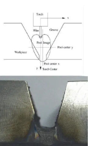
The front view of the arc and bevel for the welding of the first pass in a U-type bevel can be seen in fig.1.
Fig. 1. A schematic view of the arc, melting wire area and seam walls The arc width (Fig. 1) is calculated using eqn. (10) [14].
2 tan( ) 2
a a
W l (9)
The wall length involving with the arc edges is calculated by eqn. (10-13). 2 sin( ) 2 a vd W R l (10) 2 2 sin( ) a vd W R l (11) r l R (12) 2vd r l l l (13)
For the other passes (except for the root pass), front view of the arc and seam (for U-type seam) is like Fig. 2.
Seam walls length (front view) involving with the arc edges is computable using eqn. (14-15).
Fig. 2. A schematic view for melting area in the second pass 2 sin( ) a h vu W l l (14) 2vu h l l l (15)
If there is torch oscillation amplitude (see Fig. 3) the effective arc width can be computable by eqn. (16) [15].
2 tan( ) 2
a osc a
W A l (16)
If the effective arc width is too much compared to the melting wire area, some of the wall energy will be lost over the seam without any involving with the molten metal. Furthermore if the center of the oscillation and the seam centerline are not identical (see Fig. 4(left)), the fusion area in the both sides, will not be same.
A schematic view and a real test result are shown in Fig. 4. In this figure the center of the oscillation and the seam centerline do not coincide, additionally, the oscillation amplitude is too much, hence Fig. 4(right) has been resulted in the experiment.
Fig. 4. Unsymmetrical and extra amplitude of arc width compared to molten wire area, schematic view (left), real test result (right)
3. Experimental results
3.1 Setup
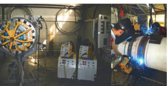
The automatic pipeline welding system used in the experiments [15] has been shown in Fig. 5. The welding progresses downward semi-circularly from top (0°) to the bottom (180°) of the pipe on each side. The solid wire was ER70S-6(SG3), having diameter of 1 mm, the shielding gas is the mixture of Argon and CO2 by 82/18 proportion.
Fig. 5. Automatic pipe line welding system in the experiments (made by Novin Sazan Co.) The pipe material is API 5L x65 HSLA steel with the thickness of 20.6 mm and the outside diameter of 32 inches. A U-type joint design is used according to fig6. Seam area is about 130mm2, that is filled with several weld passes.
Fig. 6. Joint configuration in the experiments
3.2 Experiments
Ex. 1: WHI value has been chosen equal to 32.3 J/mm2,the other parameters have been
computed as the first row in Table 2 (only root pass parameters are shown). These parameters implemented on the system. Longitudinal cross section of the weld metal (front view) is shown in Fig. 7 (left), moreover root pass reinforcement (from inside the pipe) is shown in Fig. 8 (left).
WHI(J/mm2) Ei(J/mm) L(mm) A(mm2) Ts(mm/s) Ws(mm/s) I(A) V(V) 32.3 393 8.84 15.1 14 251.7 276 24.4 Ex. 1 35.2 337 7.54 9.3 14 166.7 255 22.6 Ex. 2
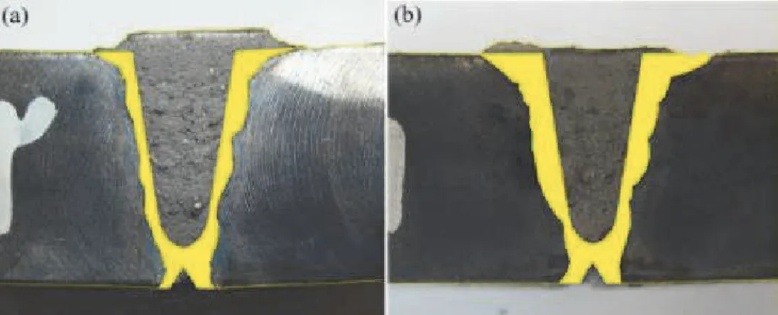
The molten base metal area is about 66mm2. This area is highlighted in Fig. 9 (a). this area
has been calculated by computer and image processing algorithms using MATLAB.
Base metal molten area over to total molten area (summing of base metal and melting wire area) is defined as relative molten area, is about 34% for this example (Ex. 1).
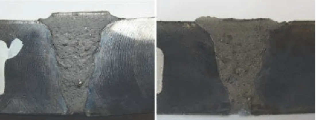
Fig. 7. Front view of the weld sections, 32.3J/mm2 WHI and 393 J/mm heat input according
to Ex. 1parameters (left); 35.2J/mm2 WHI and 337 J/mm heat input with Ex. 2 parameters
(right)
Fig. 8. Back view of welds from inside the pipe; for Ex.1 (up) andfor Ex. 2 (down), Ex. 2 has more penetration than Ex. 1 related to the more WHI
Ex. 2: WHI value has been selected equal to 35.2 J/mm2, and Parameters are calculated
according to the WHI value. Welding parameters are shown in the second row of the Table 2 (only for root pass). Comparing parameters of Ex. 1 and Ex. 2 indicates an important point: WHI increases but total heat input decreases because of the decreasing of the wire feeding rate (in Ex. 2 than Ex. 1). Cross section and back view (from inside the pipe) is shown in Fig. 7(right) and Fig. 8(right) respectively. Molten base metal area (walls molten area) is estimated to be about 105 mm2, which is shown in Fig. 9(b). Relative molten area is also
estimated to be about 45%. Because of the more WHI (despite decreasing the heat input), fusion zone and penetration has been increased.
Fig. 9. Fusion zones of metal base in Ex. 1 (32.3J/mm2 WHI) (a), and for Ex. 2 (35.2J/mm2)
(b)
4. Conclusion
In this paper WHI was introduced as a new criterion for designing of the welding parameters and welding analysis. This criterion calculates some of the heat input that is directly given to the walls from the arc. This formula considers the effects of the both required wire melting energy and seam geometry on the input energy. It was shown that WHI has a more correlation with fusion zone area compared to the heat input formula. In the other view the obtained results can be extended to the other welding processes and other applications. However WHI has a good feature in welding parameters designing to achieve some appropriate welding properties like the fusion zone.
5. References
[1]Lopes AGT (2006) Arc-Based Sensing in Narrow Groove Pipe Welding. Ph.D. Thesis, Sch. Ind. Manuf. Sci., Cranfield U.
[2]Blackman SA, Dorling DV (2000) Advanced welding processes for transmission
pipelines. In: 3rd Int. Conf., Pipeline Technol. Proc.
[3]Murugan N, Parmar RS (1994) Effects of MIG process parameters on the geometry of the
[4]Thomsen JS (2004) Advanced control methods for optimization of arc welding, Ph.D. Thesis, Department of Control Engineering, Aalborg University, Denmark, June
[5]Connor LP (1991) Welding handbook-welding processes. 8th edi. American Welding Society
[6]Benyounis KY, Olabi AG (2008) Optimization of different welding processes using
statistical and numerical approaches-A reference guide, Adv Eng Soft 39: 483-496
[7]Raveendra J, Parmar RS (1987) Mathematical models to predict weld bead geometry for
flux cored arc welding. Journal of Metal Constructions 19: 31-35.
[8]Kim IS, Son JS, Kim IG, Kim OS (2003) A study on relationship between process variable and bead penetration for robotic CO2 arc welding. Journal of Materials Processing Technology 136: 139-145.
[9]Mendez PF, Eagar TW (2003) Penetration and Defect Formation in High-Current arc
welding, Weld J, 82(10)296s-306s
[10] Okui N, Ketron D, Bordelon F, Hirata Y, Clark G (2007) A Methodology for Prediction
of Fusion Zone Shape, weld J, 35s-43s
[11] Lancaster JF (1986) The physics of welding. Pergamon Pub., 2nd edi.
[12] Lin ML, Eagar TW (1985) Influence of arc pressure on weld pool geometry, Weld J, 64
163s-169s
[13] Lancaster JF (1993) Metallurgy of welding. Chapman & Hall pub., 5th edi.
[14] Guoxiang XU, Chuansong WU (2007) Numerical analysis of weld pool geometry in
globular-transfer gas metal arc welding, Front. Mater. Sci. China, 1(1): 24–29
[15] Doodman AR, Mortazavi SA (2008) A new adaptive method (AF-PID) presentation
with implementation in the automatic welding robot, IEEE/ASME Int. Conf. Mechat. Emb. Sys. Appl., (MESA08).
ISBN 978-953-307-642-3 Hard cover, 320 pages
Publisher InTech
Published online 16, December, 2011
Published in print edition December, 2011
InTech Europe
University Campus STeP Ri Slavka Krautzeka 83/A 51000 Rijeka, Croatia Phone: +385 (51) 770 447 Fax: +385 (51) 686 166 www.intechopen.com
InTech China
Unit 405, Office Block, Hotel Equatorial Shanghai No.65, Yan An Road (West), Shanghai, 200040, China Phone: +86-21-62489820
Fax: +86-21-62489821
Ever since the invention of arc technology in 1870s and its early use for welding lead during the manufacture of lead-acid batteries, advances in arc welding throughout the twentieth and twenty-first centuries have seen this form of processing applied to a range of industries and progress to become one of the most effective techniques in metals and alloys joining. The objective of this book is to introduce relatively established methodologies and techniques which have been studied, developed and applied in industries or researches. State-of-the-art development aimed at improving technologies will be presented covering topics such as weldability, technology, automation, modelling, and measurement. This book also seeks to provide effective solutions to various applications for engineers and researchers who are interested in arc material processing. This book is divided into 4 independent sections corresponding to recent advances in this field.
How to reference
In order to correctly reference this scholarly work, feel free to copy and paste the following:
Alireza Doodman Tipi and Fatemeh Sahraei (2011). WHI Formula as a New Criterion in Automatic Pipeline GMAW Process, Arc Welding, Prof. Wladislav Sudnik (Ed.), ISBN: 978-953-307-642-3, InTech, Available from: http://www.intechopen.com/books/arc-welding/whi-formula-as-a-new-criterion-in-automatic-pipeline-gmaw-process