Hirschmüller et al. 143
Computer Vision for Mobile Robot Navigation
Heiko Hirschmüller, Korbinian Schmid, Michael Suppa, Oberpfaffenhofen / Munich
ABSTRACT
Vision is a very important sense for humans. Robots also need to be aware of their environment for working in it. This is even more important for mobile robots that operate in unknown environments that are not prepared for robots. In this paper, we focus on the aspect of navigation of mobile robots for applications in search and rescue as well as planetary exploration. We discuss a typical vision pipeline and navigation stack that has been developed at the Institute of Robotics and Mechatronics of the German Aerospace Center (DLR). In recent years, we have successfully applied the solution to a number of crawling, driving and flying robots. We present mobile systems in several applications and also discuss the relation between computer vision and photogrammetry.
1. INTRODUCTION
Robots are becoming ubiquitous in our modern world. In industry, they relieve humans from tedious, monotonous and dangerous work. At home, they do vacuum cleaning or lawn mowing. On other planets like Mars, robots explore the environment and take scientific measurements. And for search and rescue, systems for reconnaissance and tele-operated manipulation are in development. For many of these applications, robots have to be mobile and must navigate autonomously. For robots at home, autonomy is required for making them useful at all. If we would have to control and supervise the systems closely, then it would be easier to do the work ourselves. In planetary exploration, scientists want to be in control for defining the next task or next waypoint. However, a signal to Mars and back takes between 6 Minutes and 40 Minutes, depending on the constellation of Mars and Earth. This large latency prevents an effective remote control. Therefore, going to the next waypoint is done autonomously. Similarly, in search and rescue applications, humans want to define the high level tasks, but a certain level of autonomy is required to relieve the rescue workers from fine grained control of single robots or large teams of robots that may work in parallel.
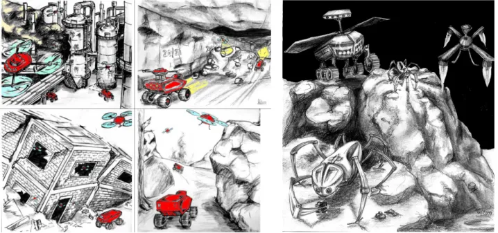
Figure 1: Applications of mobile robots in search and rescue as well as planetary exploration. Drawings by Martin Görner.
Industrial environments can be prepared for mobile robots with special markers, a certain infrastructure and central control of all systems. However, we do not want to change our home for using a vacuum cleaning robot and we cannot change the environment of Mars for making it more robot friendly. Furthermore, certain infrastructure like GPS is not available indoors or on other planets. Thus, instead of relying on external infrastructure, mobile robots should depend only on their own sensor input and on-board processing.
The kind of sensors to use depends on the environment and the size of the robot. Laser scanners deliver quite precise measurements without post-processing, but measurements are typically restricted to one plane. This is useful for indoor environments with straight walls, but not for unstructured outdoor settings. Other disadvantages are the weight and price of typical scanners, which limits their use to bigger robots.
Time-of-Flight (ToF) cameras produce a 2D depth image by sending out laser light of a certain wave length and measuring the phase-shift of the reflected light with an array of sensors. ToF cameras work indoors as well as outdoors, but their resolution is typically limited to less than VGA resolution (i.e. 640 x 480 pixel). Furthermore, the field of view and the maximum measurement distance are limited by the amount of energy that can be emitted. Not only eye safety is an issue here.
Another measurement principle is structured light, which is perceived by a camera. The popular Microsoft Kinect 1 uses a random dot projector and one camera. An internal processing unit matches the perceived pattern with an expected pattern for computing depth. Since the camera relies on the projected pattern, it does not work outdoors and interferes with other Kinect sensors. Furthermore, the maximum measurement distance is limited to just a few meters to ensure eye safety.
An alternative is passive stereo vision. Here, two calibrated cameras perceive the same scene from slightly different viewpoints. Distance is computed from the difference of both images. Cameras are quite cheap, light-weight and provide a high resolution if needed. A drawback is the processing unit that is required for image matching. Passive stereo vision depends on the texture of the scene. It works very well outdoors and less well in structured environments with large uniform textures. However, an additional projector can help to overcome problems with matching untextured surfaces. In contrast to structured light, stereo sensors do not depend on a specific pattern. Instead the projected pattern is used as an additional texture. If it cannot be perceived due to too much environmental light, then it relies just on the scene texture, which is fine for many scenes.
This paper focuses on applications of mobile robots in search and rescue as well as planetary exploration (Figure 1). The expected environments are mostly unstructured, but typically well textured. In these applications, passive stereo vision is used as main sensor.
2. VISION PIPELINE
We assume that cameras are calibrated. Thus, all intrinsic camera parameters including lens distortion are known. Furthermore, the exact rotation and translation between both cameras are available. We assume well calibrated cameras with a reprojection error below 0.5 pixel. After calibration, the intrinsic parameters as well as the relative orientation must not change. In practice, the relative rotation between both cameras is most difficult to maintain. Typically, it must not change by more than 0.02°. Another important issue is that cameras must be synchronized by hardware or software triggers so that they take pictures at exactly the same time. Otherwise, the relative orientation of the cameras would be lost.
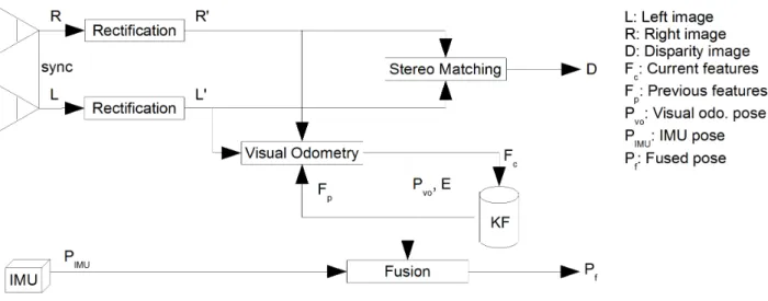
Figure 2: Vision pipeline.
After these prerequisites, images are rectified according to the calibration parameters (Figure 2). Planar rectification (Trucco and Verri, 1998) projects both images onto a common plane that has the same distance to the optical centers of both cameras. This ensures, with the right choice of the image coordinate system, that a point in the scene is always projected onto the same image row in both images. Points at infinity are also projected onto the same image column, while points that are closer, have a smaller column number in the right image as in the left image. In general, rectification simplifies all following steps and reduces processing time.
The rectified images are used for dense stereo matching. Many vision systems used correlation based stereo matching (Hirschmüller, 2002), which can be computed in real-time on the on-board computers, which are often not very powerful. Real-time in the case of mobile robots typically means that at least a few frames per second must be processed. Full framerate with 25 or 30 frames per seconds is usually not necessary.
An alternative to stereo correlation is Semi-Global Matching (SGM), which combines the accuracy and density of global stereo methods with the speed of local methods (Hirschmüller, 2008). For radiometric robustness, we use non-parametric matching costs like Census (Hirschmüller and Scharstein, 2009; Zabih and Woodfill, 1994). Figure 3 (right) shows an example disparity image that has been computed by SGM.
For real-time purposes, we use GPU (Ernst and Hirschmüller, 2008) and FPGA (Gehrig et al., 2009) implementations of SGM. On our mobile robots, we currently employ an implementation on a Spartan 6 FPGA that can process images with 1024 x 508 pixels and 128 pixel disparity range with about 14.6 Hz.
Another purpose of a vision pipeline is to compute the ego-motion of the camera from the stream of images. This is done by a technique called visual odometry. Firstly, natural features are detected by a fast corner detector like AGAST (Mair et al. 2010). Next, a robust feature descriptor should be used for extracting unique signatures. We argue against the use of SIFT features (Lowe, 2004), which are quite popular. However, the SIFT detector requires a lot of processing time and rotation or scale invariance is not needed for closely sampled image sequences. Instead, we generate signatures simply by taking a fixed window around the corners. Similarly to stereo matching, radiometric robustness is ensured by performing a Rank or Census transformation (Zabih and Woodfill, 1994) on the windows.
Figure 3: Example camera image with feature tracking (left) and disparity image (right).
Visual odometry matches the signatures of all corners to the signatures of corners of a past image. Avoiding mismatches is very important. A popular choice to achieve this is RANSAC (Fischler and Bolles, 1981), which uses a minimal set of corners as sample to compute a model. All corners that confirm the model are identified as inlier. RANSAC chooses the samples randomly within a loop. The model that maximizes the inlier is chosen as result.
We use an alternative that works without random sampling by using the 3D reconstructions of the corners (Hirschmüller et al., 2002b). For static scenes, the 3D distance between two reconstructed corners must be constant. If it differs for the two involved stereo views, then at least one of the initial correspondences must be wrong. This criterion can be used for finding a large set of inlier, even if there are more outliers than inlier (Figure 3 left).
After having a reliable set of inlier, the relative transformation between the current and the past view can be calculated in closed form by singular value decomposition, from the 3D reconstructions of the corners (Haralick et al., 1989; Arun et al., 1987). Thereafter, the reprojection error, or for the sake of speed, the ellipsoid error (Matthies and Shafer, 1987) can be minimized by non-linear optimization. Finally, the error of the transformation can be calculated by error propagation (Stelzer et al., 2012). The transformation error estimate is important for the following processing steps. Pure incremental visual odometry suffers from drift, since small errors accumulate over time. We use a keyframe based approach that computes the transformation of the current frame to a few keyframes. The transformation with the minimal error is used for further processing. Then, the current frame is inserted into the keyframe list, such that it replaces a keyframe which is not visible any more or one with a high transformation error. In this way, visual odometry is drift free if the system is standing. Furthermore, the keyframe approach reduces drift if the system is moving slow in relation to the used frame rate.
Visual odometry is very exact compared to other ways of incremental ego-motion estimation. However, it is not robust. It fails if there are no features in the scene, e.g. due to white walls, or if the movement is fast, which causes motion blur, etc. However, there are other sensors like inertial measurement units (IMU), which do not fail in these cases. An IMU measures linear accelerations as well as rotational rates at a high frequency of typically several hundred Hz. Relative pose transformations are calculated by integrating over the acceleration measurements. This is quite error prone, especially in the presence of the gravitation acceleration, which has to be compensated. However, fast movements or movements over a short time can be measured quite accurately.
Due to their oppositional properties, visual odometry and IMU measurements can complement each other very well. This is done by fusing their measurements according to their individual errors using a Kalman filter (Schmid and Hirschmüller, 2013). For visual odometry, the error is estimated for
each new frame. The error of the IMU is based on statistics. Experiments with a hand-held device confirmed that a drift of about 1% of the traveled distance can be maintained, even in the presence forced drop-outs of the vision system of several seconds during critical movements. Another advantage is that ego-motion estimates are available in the high frequency of the IMU. Together with the robustness, this permits using the fused ego-motion poses within the control loop of robotic systems.
3. NAVIGATION
The vision pipeline delivers the ego-motion of the sensor robustly and precisely. Furthermore, it produces a dense disparity image. We use both kinds of information for creating a map of the environment. Depending on the mobile robot and the application, it can either be a 2D, 2.5D or 3D map. 2D maps are useful if it is known that the ground is flat, e.g. indoors. However, we do not consider this special case.
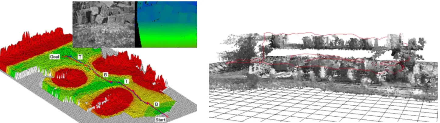
For uneven and unstructured natural outdoor environments as considered in this paper, a 2.5D map is appropriate (Stelzer et al., 2012). Here, each point on the map has an associated height. For creating such a map, the disparity images are reconstructed and transformed into a world coordinate system by using the computed ego motion. We use a statistical approach for fusing the measurements with existing information of the map. Next, the map is evaluated for traversability, by calculating the roughness and slope. Figure 4 (left) shows a map that is colorized according to traversability. The area around stones is marked by red. Green signals traversable terrain for the robot. This permits planning a safe path to a given target point. It is important, that the map changes all the time when new disparity images are integrated. Thus, the path to the target point is re-planned accordingly, if necessary.
Figure 4: 2.5D (left) and 3D (right) maps, created from dense stereo images and ego-motion measurements. 3D maps as shown in Figure 4 (right) are useful for modeling environments with more than one height above a virtual ground plane. This can be due to overhangs that must be considered by the path planner or due to modeling several floors above each other as shown in this example. A 3D map can be represented as voxel map. A voxel is either empty or occupied. Similarly to the 2.5D map, the disparity images are reconstructed and the points fused into the voxel map by a statistical approach. The only difference to the 2.5D approach is that path planning has to be done in 3D instead of a 2D grid.
The difficulty with the described approach is the drift which is still inherent in the ego-motion estimation. After traveling some time and coming back to a previously encountered location, there usually is a visible offset between the previous and current robot position, depending on the size of the loop. This problem is tackled in robotics by Simultaneous Location and Mapping (SLAM).
After recognizing a place as previously visited, the position error can be distributed over the loop. A global optimization ensures the proper distribution of errors.
The recognition of places can be done in different ways. One possibility is to work only with local maps (i.e. small maps). Registration between local maps is attempted if it appears useful. Successful registrations then lead to loop closures (Brand et al., 2014).
4. APPLICATION
The focus of this paper is on outdoor robotics. The described vision pipeline and navigation stack have been applied to different kinds of robots in different scenarios.
4.1. Search and Rescue
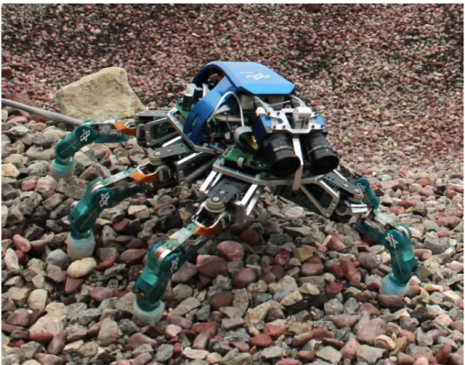
The DLR crawler is a robot with 6 legs (Figure 5). All joints are equipped with torque sensors that are used for measuring ground contact or collision with obstacles. The control algorithm is inspired from insects and adapts automatically to the ground as well as special conditions, like the loss of control of one leg (Görner et al., 2010). The robot is equipped with a stereo camera and an IMU for autonomous waypoint navigation according to Section 2. and 3. This enables the operator to select only target points. Going to the target points is done fully autonomously by the robot (Stelzer et al., 2012). A robot like the crawler can be imagined to explore small holes, e.g. in collapsed buildings, etc.
Figure 5: DLR crawler.
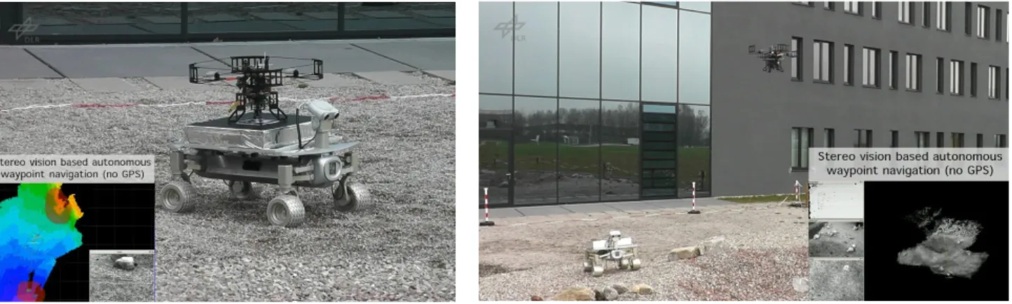
More challenging than rather slow crawling robots are flying quadcopter systems (Figure 6 left). The DLR Pelican system (Schmid et al., 2013) is equipped with stereo cameras that are looking slightly downwards, so that the scene in front as well as a part of the ground is visible. An IMU supports the visual odometry as explained in Section 2. . A Spartan 6 FPGA processes dense stereo images by SGM with 14.6 Hz. For processing intensive tasks, we used an on-board Core2Duo CPU.
The Robot Operating System (ROS) serves as framework and a voxel map integrates the depth images. In one experimental setup, we flew manually around a small building, entered it through a door, flew through a room, then upstairs to the first floor, left the building through a window and landed on the same spot as we started from. The total trajectory was about 110 m with a loop closure error of just 76 cm (Schmid et al., 2014). All processing was done in real-time on board without depending on any external infrastructure (Figure 6 right).
The next challenge is autonomous flights in which an operator only selects target points in the camera image or in the map that is built by the system. The quadcopter determines its ego motion by the combination of visual odometry and IMU measurements and uses these measurements within the control loop for stabilizing the flight. As before, a voxel map is created from depth images. The voxel map is used for incrementally planning a collision free path to the target point. At the target point, the system hovers until another target point is defined. In this way, environments not visible to the operator can be explored.
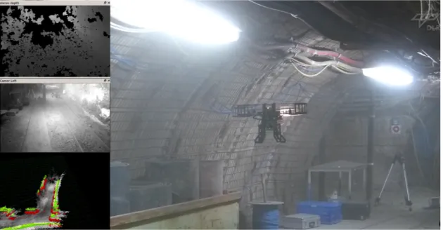
In one experiment, we took the system out of the laboratory into a coal mine (Figure 7). Since the environment is quite dark, the quadcopter was additionally equipped with LEDs that were synchronized with the exposure of the camera images. Coping with dust and air turbulences, due to narrow corridors, pushed the system to its limits. In the experiment, the operator defined target points that led the quadcopter around a corner outside direct visibility. The system successfully created a map and returned to the start position (Schmid et al., 2014).
Figure 6: DLR Pelican system (left) and output of on-board, real-time processing (right).
4.2. Planetary Exploration
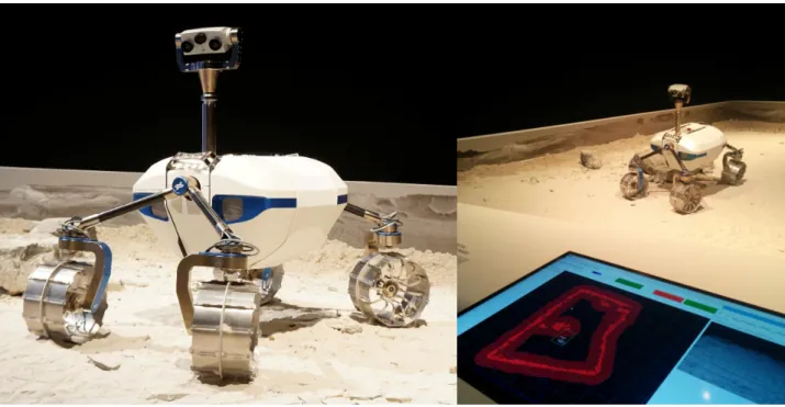
For the exploration of Moon or other planets like Mars, mobile robots play a role of increasing importance for scientists. The DLR Lightweight Rover Unit (LRU) is a prototype of the next generation of exploration rovers (Figure 8 left). It weighs about 30 kg. Each wheel has an individual motor for driving and turning. The system can move omni-directional. The front and rear boogies can be rotated separately around the body axis. In this way, the rover can adapt to difficult terrain. The system can climb slopes of 45°.
Figure 8: DLR Lightweight Rover Unit (left) and presentation of autonomous waypoint navigation (right) at Berlin Air Show (ILA) in Mai 2014.
The LRU uses a stereo camera on a pan-tilt unit as well as an IMU in the rover body. All processing as explained in Section 2. and 3. are implemented on one on-board computer that is equipped with an i7 quadcore CPU. As for the flying quadcopter systems, SGM is executed on a Spartan 6 FPGA. At the Berlin Air Show in Mai 2014, we presented controlling the system with a simulated round trip communication delay of 3 seconds, i.e. like controlling a rover on the Moon. Direct remote control is very difficult under these conditions. However, due to the on-board autonomous waypoint navigation, selected guests could mark target points in the camera image or in the map (Figure 8 right). The LRU reached these target points safely, by avoiding stones that were used as obstacles. Currently, the LRU is equipped with a manipulator for taking part in the SpaceBot Cup competition which takes place in November 2015. The task is to find two kinds of objects in an unknown, planetary like environment and put them into and onto a third object. All of this has to be done with on-board autonomy, with very little possibilities for the operation crew to intervene, like in a real space mission.
Figure 9: Rover as carrier for a quadcopter. Both systems are operated by autonomous waypoint navigation.
4.3. Cooperating Mobile Robots
Since different mobile systems have different abilities they can be combined to a robot team. In one experiment, we used a rover as carrier platform for a quadcopter as shown in Figure 9. Both systems were operated by autonomous waypoint navigation with on-board processing. The rover was sent to a spot next to a crater. The quadcopter was commanded to start and model the environment from the air. In the meantime, the rover drove to a different place. Then the quadcopter was commanded to find the rover and to land on it. All commands were just given as target or waypoints. The on-board computers of both systems controlled everything else autonomously. Future work includes building common maps for navigation and sharing them between all robots of a bigger team.
4.4. Driver Assistance Systems
Autonomous navigation of mobile systems is a research topic from which many techniques can be used for daily life applications. Daimler AG is using the SGM algorithm for supporting driver assistance systems. A stereo camera captures the scene in front of the car. SGM is implemented on a low-power FPGA (Gehrig et al., 2009). The dense depth image supports many driver assistance functions like active breaking. Figure 10 shows that SGM is much better suited for this kind of application than traditional correlation methods since SGM delivers depth images that are denser. Furthermore, it also produces less error in regions with low contrast and is robust against repetitive structures. This can be observed at the rail of the bridge.
Figure 10: Camera image with depth image overlay. Red is near and green is far away. Stereo correlation (left) and SGM (right). Courtesy of Stefan Gehrig (Daimler AG).
4.5. Roboception
Many of the techniques that were described in this paper are interesting for other researchers and industrial partners and shall be made available for the community, too. Roboception GmbH1 is a
DLR spin-off that is going to commercialize robust, real-time ego-motion estimation by fusion of visual odometry and IMU measurements. The focus is on robustness, the possibility to include the measurements in the control loop of robotic systems as well as low computational power requirements, e.g. processing on light-weight, embedded ARM processor boards. Also depth images by Semi-Global Matching will be available. Last but not least, a general ROS interface will enable the product integration with different kinds of robots easily.
5. DISCUSSION
We have described the components of a typical vision and navigation pipeline for mobile robots. A variety of robots for different applications were presented. While the focus was on outdoor robotics, we have shown that the robots were also capable of indoor navigation.
Important for computer vision in robotics are robustness and speed. Computer vision methods may be used within the control loop of robotic systems. Failures of vision methods endanger system control and autonomous operations. This is in contrast to photogrammetry, where automatic computation is nice for reducing human workload, but a fall back to human work is acceptable. On the other hand accuracy does not have the highest priority in computer vision. However, in photogrammetry it is a major goal.
These differences should be kept in mind when looking at solutions in the fields of computer vision or photogrammetry. Finally, an innovation-driven way to make the technology available is presented.
6. REFERENCES
Arun, K. S., Hunag, T. S. and Blostein, S. D. (1987): Least-Squares Fitting of Two 3-D Point Sets. IEEE Transactions on Pattern Analysis and Machine Intelligence, Volume 9 (5), pp. 698-700. Brand, C., Schuster, M. J., Hirschmüller, H. and Suppa, M. (2014): Stereo-Vision Based Obstacle
Mapping for Indoor / Outdoor SLAM. In: International Conference on Robotic Systems (IROS), Chicago, USA.
Ernst, I. and Hirschmüller, H. (2008): Mutual Information based Semi-Global Stereo Matching on the GPU. In: International Symposium on Visual Computing (ISVC08), December 2008, Las Vegas, Nevada, USA.
Fischler, M. A. and Bolles, R. C. (1981): Random Sample Consensus: A Paradigm for Model Fitting with Application to Image Analysis and Automated Cartography. Communications of the ACM, Volume 24(6), pp. 381-395.
Gehrig, S., Eberli, F. and Meyer, T. (2009): A Real-Time Low-Power Stereo Vision Engine using Semi-Global Matching. In: International Conference on Computer Vision Systems (ICVS), LNCS 5815, Liege, Belgium.
Görner, M., Chilian, A. and Hirschmüller, H. (2010): Towards and Autonomous Walking robot for Planetary Surfaces. In: The 10th International Symposium on Artificial Intelligence, robotics and Automation in Space (i-SAIRAS), Sapporo, Japan.
Haralick, R., Joo, H., Lee, C.-N., Zhuang, X., Vaidya, V. G. and Kim, M. B. (1989): Pose estimation from corresponding point data. IEEE Transactions on Systems, Man, and Cybernetics, Volume 19 (6), pp. 1426-1446.
Hirschmüller, H., Innocent, P. R. and Garibaldi, J. M. (2002): Real-Time Correlation-Based Stereo Vision with Reduced Border Errors. International Journal of Computer Vision, 47 (1/2/3), pp. 229-246.
Hirschmüller, H., Innocent, P. R. and Garibaldi, J. M. (2002b): Fast, Unconstrained Camera Motion Estimation from Stereo without Tracking and Robust Statistics. In: Proceedings of the 7th International Conference on Control, Automation, Robotics and Vision, Singapore 2002, pp. 1099-1104.
Hirschmüller, H. (2008): Stereo Processing by Semi-Global Matching and Mutual Information. IEEE Transactions on Pattern Analysis and Machine Intelligence, Volume 30 (2), February 2008, pp. 328-341.
Hirschmüller, H. and Scharstein, D. (2009): Evaluation of Stereo Matching Costs on Images with Radiometric Differences. In: IEEE Transactions on Pattern Analysis and Machine Intelligence, Volume 31 (9), September 2009, pp. 1582-1599.
Lowe, D. G. (2004), Distinctive Image Features from Scale-Invariant Keypoints. International Journal of Computer Vision, Volume 60 (2), pp. 91-110.
Mair, E., Hager, G., Burschka, D., Suppa, M. and Hirzinger, G. (2010): Adaptive and generic corner detection based on the accelerated segment test. In: European Conference on Computer Vision (ECCV) 2010, pp. 183-196.
Matthies, L. and Shafer, S. A. (1987): Error modeling in stereo navigation. IEEE Journal on Robotics and Automation, Volume 3 (3), pp. 239-248.
Schmid, K. and Hirschmüller, H. (2013), Stereo Vision and IMU based Real-Time Ego-Motion and Depth Image Computation on a Handheld Device. In: IEEE International Conference on Robotics and Automation, Karlsruhe, Germany.
Schmid, K., Tomic, T., Ruess, F., Hirschmüller, H. and Suppa, M. (2013): Stereo Vision based indoor/outdoor Navigation for Flying Robots. In: IEEE/RSJ International Conference on Intelligent Robots and Systems (IROS), Tokyo, Japan.
Schmid, K., Lutz, P., Tomic, T., Mair, E. and Hirschmüller, H. (2014): Autonomous Vision-based Micro Air Vehicle for Indoor and Outdoor Navigation. Journal of Field Robotics, Special Issue on Low Altitude Flight of UAVs, Volume 31 (4), pp. 537-570.
Stelzer, A., Hirschmüller, H. and Görner, M. (2012): Stereo-vision-based navigation of a six-legged walking robot in unknown rough terrain. International Journal of Robotics Research: Special Issue on Robot Vision, Volume 31 (4), pp. 381-402.
Trucco, E. and Verri, A. (1998): Introductory Techniques for 3-D Computer Vision. Prentice-Hall, 1998.
Zabih, R. and Woodfill, J. (1994): Non-parametric local transforms for computing visual correspondence. In: Proceedings of the European Conference of Computer Vision, Stockholm, Sweden, pp. 151-158.