Fr´
ed´
eric Beck
To cite this version:
Fr´
ed´
eric Beck. NetFlow, RMON and Cisco-NAM deployment. [Technical Report] RT-0343,
INRIA. 2007, pp.27.
<
inria-00169995v3
>
HAL Id: inria-00169995
https://hal.inria.fr/inria-00169995v3
Submitted on 2 Nov 2007
HAL
is a multi-disciplinary open access
archive for the deposit and dissemination of
sci-entific research documents, whether they are
pub-lished or not.
The documents may come from
teaching and research institutions in France or
abroad, or from public or private research centers.
L’archive ouverte pluridisciplinaire
HAL
, est
destin´
ee au d´
epˆ
ot et `
a la diffusion de documents
scientifiques de niveau recherche, publi´
es ou non,
´
emanant des ´
etablissements d’enseignement et de
recherche fran¸cais ou ´
etrangers, des laboratoires
publics ou priv´
es.
Th `eme COM
NetFlow, RMON and Cisco-NAM deployment
Fr´ed´eric Beck
N° 0343
Fr´
ed´
eric Beck
Th`eme COM — Syst`emes communicants Projet MADYNES
Rapport technique n°0343 — August 2007 — 24 pages
Abstract: In this report, we present the deployment of NetFlow, RMON and the Cisco Network Analysis Module, Cisco-NAM, on the team testbed. First, we present the different technologies, and then we describe their deployment and how they were integrated in the teams testbed.
R´esum´e : Dans ce rapport, nous pr´esentons le d´eploiement de NetFlow, RMON et du module d’analyse de trafic CISCO-NAM sur le testbed de l’´equipe. Nous pr´esentons dans un premier temps les diff´erentes technologies, avant de d´ecrire toutes les ´etapes relatives `a leur d´eploiement et int´egration au testbed.
Contents
1 Introduction 5 2 Netflow 5 2.1 Protocol description . . . 6 2.2 Network Flows . . . 6 2.3 Netflow Record . . . 62.4 Cisco’s Sampled NetFlow . . . 7
2.5 Versions . . . 7
3 RMON 8 3.1 Overview . . . 8
4 Cisco Network Analysis Module 10 4.1 Overview . . . 10
4.2 NAM Network Interfaces . . . 10
4.2.1 Analysis Module Interface . . . 11
4.2.2 External NAM Interface . . . 11
4.2.3 Internal NAM Interface . . . 11
4.3 NM-NAM Operating Topologies and IP Address Assignments . . . 11
4.3.1 Management Traffic . . . 11 4.3.2 Monitored Traffic . . . 12 5 Deployment 13 5.1 Testbed Architecture . . . 13 5.2 NetFlow Deployment . . . 14 5.2.1 Router Configuration . . . 14 5.2.2 Collector Configuration . . . 15 5.3 NM-NAM Deployment . . . 16
5.3.1 Configuring the Analysis-Module Interface on the Router . . . 17
5.3.2 Opening and Closing a NAM Console Session from the Router . . . . 18
5.3.3 Configuring the NAM . . . 18
5.3.4 Configuring a Static Route to the NAM Through the Analysis-Module Interface 19 5.3.5 Enabling NAM Packet Monitoring . . . 20
5.3.6 Enabling and Accessing the NAM Traffic Analyzer . . . 21
5.3.7 Accessing the NAM Traffic Analyzer . . . 21
5.4 RMON Deployment . . . 21
5.4.1 SNMP Server . . . 23
5.4.2 Configuring RMON support . . . 23
List of Figures
1 Netflow Architecture . . . 5
2 NAM Network Interfaces . . . 10
3 Testbed Architecture . . . 13
4 Ntop - Add NetFlow Device . . . 16
5 Ntop - NetFlow Hosts Summary . . . 17
1
Introduction
In this paper, we will present the deployment and configuration of Netflow [1] and RMON [4] on our testbed.
We will first present both technologies, and then present the configuration and deploy-ment of each solution our testbed.
2
Netflow
NetFlow1
is an open but proprietary network protocol developed by Cisco Systems to run on Cisco IOS-enabled equipment for collecting IP traffic information.
Figure 1 shows an architecture of Netflow deployment.
Figure 1: Netflow Architecture
1
2.1
Protocol description
Cisco routers that have the Netflow feature enabled generate netflow records; these are exported from the router in User Datagram Protocol (UDP) or Stream Control Transmission Protocol (SCTP) packets and collected using a netflow collector. Juniper Networks provides a similar feature for its routers called Jflow . Huawei Technology routers also support the same technology, but call it NetStream.
2.2
Network Flows
Network flows have been defined in many ways. In the case of NetFlow, Cisco uses the common 5-tuple definition, where a flow is defined as a unidirectional sequence of packets all sharing all of the following 5 values:
1. Source IP address 2. Destination IP address 3. Source TCP port 4. Destination TCP port 5. IP protocol
The router will output a flow record when it determines that the flow is finished. It does this by flow aging: when the router sees new traffic for an existing flow it resets the aging counter. Also, TCP session termination in a TCP flow causes the router to expire the flow. Routers can also be configured to output a flow record at a fixed interval even if the flow is still ongoing. In Flexible NetFlow (FNF) an administrator could actually define flow properties on the router.
2.3
Netflow Record
A NetFlow record can contain a wide variety of information about the traffic in a given flow. NetFlow version 5 (one of the most commonly used versions, followed by version 9) contains the following:
Version number Sequence number
Input and output interface snmp indices Timestamps for the flow start and finish time Number of bytes and packets observed in the flow
Layer 3 headers:
– Source and destination IP addresses
– Source and destination port numbers
– IP protocol
– Type of Service (ToS) value
In the case of TCP flows, the union of all TCP flags observed over the life of the flow.
Some routers will also include the source and destination Autonomous System (AS) number, though this information can be inaccurate. NetFlow version 9 can include all of these fields and can optionally include additional information such as Multiprotocol Label Switching (MPLS) labels and IPv6 addresses and ports,
By analyzing flow data, a picture of traffic flow and traffic volume in a network can be built. The NetFlow record format has evolved over time, hence the inclusion of version numbers. Cisco maintains details of the different version numbers and the layout of the packets for each version.
NetFlow records are usually sent via a UDP or SCTP in newer software, and for efficiency reasons, the router does not store flow records once they are exported. Therefore, if the NetFlow record is dropped due to network congestion, it is lost forever – there’s no way for the router to resend it (this is correct for UDP NetFlow only). The IP address of the netflow collector and the port upon which it is listening must be configured on the sending router but is usually either on ports 2055, 9555, or 9995. NetFlow is also enabled on a per-interface basis to avoid unnecessarily burdening of the router’s CPU. NetFlow is generally based on the packets input to interfaces where it is enabled. This avoids double counting and saves work for the router. It also allows the router to export NetFlow records for dropped packets.
2.4
Cisco’s Sampled NetFlow
Maintaining NetFlow data can be computationally expensive for the router and burden the router’s CPU to the point where it runs out of capacity. To avoid problems caused by router CPU exhaustion, Cisco provides ”Sampled NetFlow”. Rather than looking at every packet to maintain NetFlow records, the router looks at every nth packet, where n can be configured (as in Deterministic NetFlow, used on Cisco’s GSRs) or it is a randomly selecting interval (as used in Random Sampled Netflow, used on all other Cisco platforms). When Sampled NetFlow is used, the NetFlow records must be adjusted for the effect of sampling - traffic volumes, in particular, are now an estimate rather than the actual measured flow volume.
2.5
Versions
Different versions of Netflow exist:
v5 Most used version
v6 Encapsulation information
v7 Switch information
v8 Several aggregation forms
v9 Template Based, allowing many combinations
IPFIX aka v10; IETF Standardized NetFlow 9 with Enterprise fields and other community input
3
RMON
The Remote Network MONitoring (RMON)2
MIB was developed by the IETF to support monitoring and protocol analysis of LANs. The original version (sometimes referred to as RMON1 [3]) focused on OSI Layer 1 and Layer 2 information in Ethernet and Token Ring networks. It has been extended by RMON2 [2] which adds support for Network-and Application-layer monitoring Network-and by SMON which adds support for switched networks. It is an industry standard specification that provides much of the functionality offered by proprietary network analyzers. RMON agents are built into many high-end switches and routers (such as those built by 3Com and Cisco).
3.1
Overview
An RMON implementation typically operates in a client/server model. Monitoring devices (commonly called ”probes” in this context) contain RMON software agents that collect information and analyze packets. These probes act as servers and the Network Management applications that communicate with them act as clients. While both agent configuration and data collection use SNMP, RMON is designed to operate differently than other SNMP-based products:
Probes have more responsibility for data collection and processing, which reduces
SNMP traffic and the processing load of the clients.
Information is only transmitted to the management application when required, instead
of continuous polling.
In short, RMON is designed for ”flow-based” monitoring, while SNMP is often used for ”device-based” management. The disadvantage is that remote devices shoulder more of the management burden, and require more resources to do so. Some devices balance this trade-off by implementing only a subset of the RMON MIB groups (see below). A minimal
2
RMON agent implementation could support only statistics, history, alarm, and event. The RMON1 MIB consists of ten groups:
1. Statistics: real-time LAN statistics e.g. utilization, collisions, CRC errors 2. History: history of selected statistics
3. Alarm: definitions for RMON SNMP traps to be sent when statistics exceed defined thresholds
4. Hosts: host specific LAN statistics e.g. bytes sent/received, frames sent/received 5. Hosts top N: record of N most active connections over a given time period 6. Matrix: the sent-received traffic matrix between systems
7. Filter: defines packet data patterns of interest e.g. MAC address or TCP port 8. Capture: collect and forward packets matching the Filter
9. Event: send alerts (SNMP traps) for the Alarm group 10. Token Ring: extensions specific to Token Ring
The RMON2 MIB adds ten more groups:
1. Protocol Directory: list of protocols the probe can monitor 2. Protocol Distribution: traffic statistics for each protocol
3. Address Map: maps network-layer (IP) to MAC-layer addresses 4. Network-Layer Host: layer 3 traffic statistics, per each host
5. Network-Layer Matrix: layer 3 traffic statistics, per source/destination pairs of hosts 6. Application-Layer Host: traffic statistics by application protocol, per host
7. Application-Layer Matrix: traffic statistics by application protocol, per source/destination pairs of hosts
8. User History: periodic samples of user-specified variables 9. Probe Configuration: remote config of probes
4
Cisco Network Analysis Module
In this chapter, we will summarize all the required informations from the different official Cisco documentations which permit to understand what is the Cisco Network Analysis Module and how it works.
4.1
Overview
The Network Analysis Module3
(NM-NAM) is a network module installed in Cisco4
routers that monitors and analyzes network traffic. The NAM Traffic Analyzer is software embedded in the NAM that gives you browser-based access to the monitoring features of the NAM. You use this software to troubleshoot and monitor network availability and health. This software runs on a Linux Distribution embedded in the NAM.
The NAM Traffic Analyzer can be access through a WEB interface. Nevertheless, it has
strong requirements for the WEB browser used, as shown athttp://www.cisco.com/en/US/products/sw/cscowork/ps
4.2
NAM Network Interfaces
The NAM uses three interfaces for communication (see Figure 2): 1. Analysis Module Interface
2. External NAM Interface 3. Internal NAM Interface
Figure 2: NAM Network Interfaces
3
http://www.cisco.com/go/nam
4
4.2.1 Analysis Module Interface
Use the Analysis-Module interface to access the NAM console for the initial configuration. After configuring the NAM IP parameters, use the Analysis-Module typically only during NAM software upgrades and while troubleshooting if the NAM Traffic Analyzer is inacces-sible.
Visible only to the Cisco IOS software on the router, the Analysis-Module interface is an internal Fast Ethernet interface on the router that connects to the internal NAM interface. The Analysis-Module interface is connected to the router’s Peripheral Compo-nent Interconnect (PCI) backplane, and perform all configuration and management of the Analysis-Module interface from the Cisco IOS CLI.
4.2.2 External NAM Interface
Use the external NAM interface to monitor LAN traffic. You can also select the external NAM interface as the management interface for the NAM.
Visible only to the NAM software on the NM-NAM, the external NAM interface is the Fast Ethernet interface on the NM-NAM faceplate. The external NAM interface supports data requests and data transfers from outside sources, and it provides direct connectivity to the LAN through an RJ-45 connector. You must perform all configuration and management of the external NAM interface from the NAM software.
4.2.3 Internal NAM Interface
Use the internal NAM interface for monitoring traffic that passes through router interfaces. You can also select the internal NAM interface as the management interface for the NAM. Visible only to the NAM software on the NM-NAM, the internal NAM interface is the Fast Ethernet interface on the NM-NAM that connects to the Analysis-Module interface on the router. The internal NAM interface is connected to the PCI bus on the NM-NAM, and you must perform all configuration and management of the internal NAM interface from the NAM software.
4.3
NM-NAM Operating Topologies and IP Address Assignments
4.3.1 Management Traffic
Select either the internal or external NAM interface to handle management traffic such as IP, HTTP, SNMP, Telnet, and SSH. You cannot send management traffic through both NAM interfaces at the same time.
External NAM Interface for Management Traffic
For the Analysis-Module interface (in Cisco IOS CLI), we recommend that you use
the IP unnumbered interface configuration to borrow the IP address of another router interface. The subnet does not need to be routable.
For the NAM system (in NAM CLI), assign an IP address from the subnet that is
connected to the external NAM interface.
Internal NAM Interface for Management Traffic
If you select the internal NAM interface to handle management traffic:
For the Analysis-Module interface (in the Cisco IOS CLI), assign an IP address from a
routable subnet. To conserve IP address space, you can configure the Analysis-Module as an IP unnumbered interface and borrow the IP address of another router interface, such as a Fast Ethernet or loopback interface. The borrowed IP address must come from a routable subnet.
For the NAM system (in the NAM CLI), assign an IP address from the same subnet
that is assigned to the Analysis-Module interface.
4.3.2 Monitored Traffic
It is possible to use either or both the internal and external NAM interfaces for monitoring traffic. The same interface can be used for both management traffic and monitored traffic simultaneously.
Internal NAM Interface - Monitor LAN and WAN Traffic
When you monitor traffic through the internal NAM interface, you must enable NAM packet monitoring on each router interface that you want to monitor. NAM packet monitoring uses Cisco Express Forwarding to send a copy of each packet that is received from or sent out of the router interface to the NAM.
Monitoring traffic through the internal NAM interface enables the NAM to see any encrypted traffic after it is decrypted by the router. It is recommended to use the internal NAM interface to monitor WAN interfaces.
External NAM Interface - Monitor LAN Traffic
Monitoring traffic through the external NAM interface does not impact router resources. Therefore, we recommend that you use the external NAM interface to monitor LAN traffic. To monitor ports on Ethernet switching cards or modules (NM-16ESW-x, NMD-36ESW-x, HWIC-4ESW, or HWIC-D-9ESW), configure a Switched Port Analyzer (SPAN) session whose destination is the Ethernet switch port that connects to the external NAM interface.
5
Deployment
5.1
Testbed Architecture
Figure 3 presents the architecture of our testbed.
Figure 3: Testbed Architecture
The testbed runs a dual-stack IP network. The IPv4 prefix is152.81.48.0/24 whereas the IPv6 prefix is 2001:660:4501:3200::/56. The interconnection with the Loria IPv6 network
is performed through the subnet 2001:660:4501:32::/64. IPv6 addresses are not assigned permanently yet, as the testbed is used for a study on IPv4 to IPv6 transition.
Chocolat and Kran are Quagga routers, whereas Kunu and Garou are Cisco 2821 routers. Chocolat is the border router. It is the gateway of our network. It runs a TFTP/FTP server for saving of all routers configurations, a DNS server for the domain madynes.loria.fr and various network management/monitoring applications such as Ntop5
.
All Quagga routers are configurable by Telnet, whereas Cisco ones also have the possi-bility to be configured by SSH. The password for connecting to the Quagga routers isdfgdfg, and the couple user/password to use for Cisco routers isadmin/dfgdfg.
5.2
NetFlow Deployment
NetFlow has been activated on the router named kunu. In this section, we will present the configuration of the router itself and the collector.
5.2.1 Router Configuration
The configuration of the router is quite simple for IPv4. First, we need to enable NetFlow on interfaces:
1. Connect to the router 2. enable
3. configure terminal
4. interface ¡interface type¿ ¡interface number¿: specifies the interface on which we want to enable NetFlow
5. ip flow ¡egress—ingress¿: enable NetFlow for outgoing/incoming traffic. 6. exit
7. Repeat steps 3 through 5 to enable NetFlow on other interfaces
Then, we need to configure the exportation of the collected data. 1. Connect to the router
2. enable
3. configure terminal
4. ip flow-export destination ¡ip address¿ ¡UDP port¿: specifies the IP address or host-name of the NetFlow collector
5
5. Repeat step 3 once to configure a second NetFlow export destination (optional) 6. ip flow-export source ¡interface type¿ ¡interface number¿ (optional): specifies the source
IP address of the UDP packets sent to the collector
7. ip flow-export version ¡1—5—9¿ (optional): specifies the version of NetFlow to be used For IPv6, the same operations can be done, simply by replacing the keywordip byipv6. These steps applied onkunu, we obtain the following configuration:
!
interface GigabitEthernet0/0
description Configured by Telnet... ip address dhcp duplex auto speed auto ! interface GigabitEthernet0/1 ip address 152.81.48.225 255.255.255.224 ip flow ingress ip flow egress duplex auto speed auto !
ip flow-export source GigabitEthernet0/0 ip flow-export version 5
ip flow-export destination 152.81.48.2 1664 !
ipv6 flow-export source GigabitEthernet0/0 ipv6 flow-export version 5
ipv6 flow-export destination 152.81.48.2 1665 !
5.2.2 Collector Configuration
Once the router is configured for collecting and exporting the data, we have to configure a collector to receive, treat and display these informations. We chose to use the Open Source NetFlow plugin for Ntop6
. The configuration procedure is the following one: 1. select the Stats menu (top menu)
2. select the Plugins links from the left menu 3. select the NetFlow plugin
6
4. select Configure 5. select Add Device
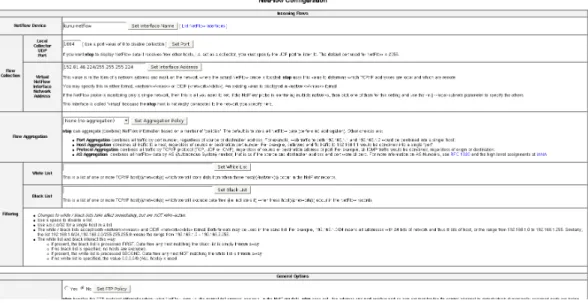
At this step, fill all the informations about the flow received as shown in figure 5.
Figure 4: Ntop - Add NetFlow Device
Once the device is created, it is mandatory tochange the NIC to display informa-tions received on this device. This is done in the menuAdmin-¿Switch NIC. Then, all the informations displayed in the various menus and items are the ones sent by the probe. Figure??shows the host summary information Ntop generated thanks to the data sent by the probe.
This screen and other informations collected are available at the URLhttp://152.81.48.2:3000.
5.3
NM-NAM Deployment
The configuration of the NAM is done in two steps:
Configure the analysis-module interface in the router Configure the NAM itself in its own interface
Figure 5: Ntop - NetFlow Hosts Summary
5.3.1 Configuring the Analysis-Module Interface on the Router
1. Connect to the router 2. enable
3. configure terminal
4. interface ¡interface type¿ ¡interface number¿: (Optional) Configures an interface, and enters interface configuration mode. Perform this step if you plan to configure the Analysis-Module interface as an IP unnumbered interface.
5. interface analysis-module slot/0
6. ip unnumbered interface number: Configures the Analysis-Module interface as IP un-numbered and specifies the interface whose IP address is borrowed by the Analysis-Module interface.
7. orip address ip-address mask: Sets an IP address and mask on the Analysis-Module interface.
8. no shutdown 9. end
In our testbed, we decided to use an unnumbered interface. Therefore, we borrowed the address of the second Ethernet slot:
interface Analysis-Module1/0 ip unnumbered GigabitEthernet0/1 hold-queue 60 out
5.3.2 Opening and Closing a NAM Console Session from the Router
In order to connect to the NAM configuration interface (at least the first time), we have to use the following procedure:
1. Connect to the router 2. enable
3. service-module analysis-module slot/0 session 4. Press Return.
5. At the login prompt, enter root.
6. At the password prompt, enter your password.
7. Perform the tasks that you need to perform in the NAM CLI. When you want to end the NAM console session and return to the Cisco IOS CLI, complete Step 8 to Step 11.
8. exit
9. Hold Ctrl-Shift and press 6. Release all keys, and then press x. 10. disconnect
11. Press Enter.
In our case, the password for the user root isdfgdfg.
5.3.3 Configuring the NAM
This section describes how to configure the NM-NAM to establish network connectivity and configure IP parameters. This task must be performed from the NAM CLI. For more advanced NAM configuration, use the NAM Traffic Analyzer.
Before doing this procedure, access the NAM console by performing Step 1 to Step 5 in section 5.3.2. Then, follow the procedure:
1. ip interface ¡internal — external¿: Specifies which NAM interface will handle manage-ment traffic.
3. ip broadcast broadcast-address: (Optional) Configures the NAM system broadcast address.
4. ip gateway ip-address: Configures the NAM system default gateway address.
5. exsession on or exsession on ssh: (Optional) Enables outside logins by Telnet or SSH. 6. ip domain name: (Optional) Sets the NAM system domain name.
7. ip host name: (Optional) Sets the NAM system hostname.
8. ip nameserver ip-address ¡ip-address¿ ¡ip-address¿: (Optional) Sets one or more NAM system name servers.
In our testbed, we chose to use an internal interface, and to give it the address152.81.48.99. The NAM gateway is the second Ethernet slot on the router with the address152.81.48.97. This gives us the following configuration on the NAM:
ip interface internal ! ip address 152.81.48.99 255.255.255.224 ! ip host "madynes-nam" ! ip domain "madynes.loria.fr" ! ip gateway 152.81.48.97 ! ip broadcast 152.81.48.127 ! ip nameserver 152.81.1.128 152.81.1.25
5.3.4 Configuring a Static Route to the NAM Through the Analysis-Module Interface
This procedure ensures that the router can route packets to the NAM by configuring a static route through the Analysis-Module interface.
If you select the internal NAM interface to handle management traffic, then configuring a static route to the NAM through the Analysis-Module interface is:
Required when the Analysis-Module interface is IP unnumbered
Recommended when the Analysis-Module interface is assigned a unique IP address
1. Connect to the router 2. enable
3. configure terminal
4. ip route nam-ip-address mask analysis-module slot/unit 5. end
In our case, the configured route is:
ip route 152.81.48.99 255.255.255.255 Analysis-Module1/0 5.3.5 Enabling NAM Packet Monitoring
This section describes how to enable NAM packet monitoring on router interfaces that you want to monitor through the internal NAM interface.
When you enable NAM packet monitoring on an interface, Cisco Express Forwarding sends an extra copy of each IP packet that is received from or sent out on that interface to the NAM through the Analysis-Module interface on the router and the internal NAM interface.
1. Connect to the router 2. enable
3. configure terminal
4. ip cef: Enables the Cisco Express Forwarding switching path.
5. interface ¡interface type¿ ¡interface number¿: Selects an interface for configuration. 6. analysis-module monitoring: Enables NAM packet monitoring on the interface.
Repeat Step 4 and Step 5 for each interface that you want the NAM to monitor through the internal NAM interface.
7. end
We decided to monitor both Ethernet interfaces on the router:
interface GigabitEthernet0/0 ip address dhcp duplex auto speed auto analysis-module monitoring ! interface GigabitEthernet0/1 ip address 152.81.48.97 255.255.255.224 duplex auto speed auto analysis-module monitoring
5.3.6 Enabling and Accessing the NAM Traffic Analyzer
This procedure enables and accesses the NAM Traffic Analyzer (web GUI). You can use the HTTP server or the HTTP secure server and you cannot use both simultaneously.
1. Open a NAM console session from the router or Open a Telnet or SSH session to the NAM.
2. ip http ¡secure¿ server enable: Enables the HTTP or HTTPS server. 3. Enter a web username.
4. Enter a password.
5. Enter the password again.
We chose the couple username/passwordadmin/dfgdfg:
web-user user-name admin account-mgmt enable system-config enable capture enable alarm-config enable collection-config enable encrypted-password "ZGZnZGZnCg==" exit ! ip http port 80 ! ip http secure port 443 !
ip http secure server disable !
ip http server enable
5.3.7 Accessing the NAM Traffic Analyzer
The NAM and its Traffic Analyzer are now configured. It is possible to access it with a web browser at the URL http://152.81.48.99/. After entering the username and password, we can configure or view the data captured.
Figure 6 shows an overview of the traffic captured.
5.4
RMON Deployment
The RMON option identifies activity on individual nodes and allows you to monitor all nodes and their interaction on a LAN segment. Used in conjunction with the SNMP agent
in a router, RMON allows you to view both traffic that flows through the router and segment traffic not necessarily destined for the router. Combining RMON alarms and events (classes of messages that indicate traffic violations and various unusual occurrences over a network) with existing MIBs allows you to choose where proactive monitoring will occur.
Full RMON packet analysis (as described in RFC 1757) is supported only on an Ether-net interface of Cisco 2500 series routers and Cisco AS5200 series universal access servers. RMON requires that SNMP be configured (you must be running a version of SNMP on the server that contains the RMON MIB). A generic RMON console application is recommended in order to take advantage of the RMON network management capabilities. This feature supports RFCs 1757 and 2021.
Therefore, in our testbed, the router garou and especially the NAM are implementing RMON.
5.4.1 SNMP Server
The NAM runs a SNMP server. It is configured as follows:
snmp community madynes-nam rw !
snmp contact "Frederic Beck - frederic.beck@loria.fr" !
snmp location "LORIA B113, Nancy, France" !
snmp name "MADYNES-NAM"
We have a read and write access to SNMP data on the host via the community madynes-nam
5.4.2 Configuring RMON support
On the router, integrated in the IOS, we can configure a limited RMON support, with only
alarms and events groups (http://www.cisco.com/univercd/cc/td/doc/product/software/ios122/122cgcr/ffun_c/
Basing itself on the packet captured, the NAM fills the RMON MIBs at the OID
1.3.6.1.2.1.16 or mib-2.16.
All configuration issues are performed through the WEB interface, in the tabCapture.
For more informations about the NAM Traffic Analyzer, refer tohttp://www.cisco.com/en/US/products/sw/cscowork
6
Conclusion
Several technologies are deployed on the testbed (Cisco NAM, Netflow, RMON, SNMP...) and are ready to be used.
References
[1] B. Claise. Cisco Systems NetFlow Services Export Version 9. RFC 3954 (Informational), October 2004.
[2] S. Waldbusser. Remote Network Monitoring Management Information Base Version 2 using SMIv2. RFC 2021 (Proposed Standard), January 1997.
[3] S. Waldbusser. Remote Network Monitoring Management Information Base. RFC 2819 (Standard), May 2000.
[4] S. Waldbusser, R. Cole, C. Kalbfleisch, and D. Romascanu. Introduction to the Remote Monitoring (RMON) Family of MIB Modules. RFC 3577 (Informational), August 2003.
615, rue du Jardin Botanique - BP 101 - 54602 Villers-l`es-Nancy Cedex (France)
Unit´e de recherche INRIA Futurs : Parc Club Orsay Universit´e - ZAC des Vignes 4, rue Jacques Monod - 91893 ORSAY Cedex (France)
Unit´e de recherche INRIA Rennes : IRISA, Campus universitaire de Beaulieu - 35042 Rennes Cedex (France) Unit´e de recherche INRIA Rhˆone-Alpes : 655, avenue de l’Europe - 38334 Montbonnot Saint-Ismier (France) Unit´e de recherche INRIA Rocquencourt : Domaine de Voluceau - Rocquencourt - BP 105 - 78153 Le Chesnay Cedex (France)